

Page 1

Installation Instructions
Kinetix 6000M Hybrid Coupler Cable
Catalog Number 2090-CCPP8S8
Topi c Page
Important User Information 2
Before You Begin 3
Install the Cable 5
2090-CCPP8S8 Cable Schematic and Connector Pinouts 6
Specifications 7
Additional Resources 7
About the Hybrid Coupler
The Kinetix® 6000 hybrid coupler cable extends the length of a cable run, or bypasses an
integrated drive-motor (IDM) unit during service or repair. It connects hybrid cables that
already are installed and reestablishes the hybrid cable daisy chain.
Page 2
2 Kinetix 6000M Hybrid Coupler Cable
Important User Information
Solid state equipment has operational characteristics differing from those of electromechanical equipment. Safety Guidelines for
the Application, Installation and Maintenance of Solid State Controls, publication SGI-1.1
Automation sales office or online at http://www.rockwellautomation.com/literature
between solid state equipment and hard-wired electromechanical devices. Because of this difference, and also because of the
wide variety of uses for solid state equipment, all persons responsible for applying this equipment must satisfy themselves that
each intended application of this equipment is acceptable.
In no event will Rockwell Automation, Inc. be responsible or li able for indirect or consequential damages resulting from the use or
application of this equipment.
The examples and diagrams in this manual are included solely for illustrative purposes. Because of the many variables and
requirements associated with any particular installation, Rockwell Automation, Inc. cannot assume responsibilit y or liability for
actual use based on the examples and diagrams.
No patent liability is assumed by Rockwell Automation, Inc. with respect to use of information, circuits, equipment, or software
described in this manual.
Reproduction of the contents of this manual, in whole or in part, without written permission of Rockwell Automation, Inc., is
prohibited.
Throughout this manual, when necessary, we use notes to make you aware of safety considerations.
WARNIN G: Identifies information about practices or circumstances that can cause an explosion in a
hazardous environment, which may lead to personal injury or death, property damage, or economic
loss.
, is available from your local Rockwell
) describes some important differences
ATTENTION: Identifies information about practices or circumstances that can lead to personal injury or
death, property damage, or economic loss. Attentions help you identify a hazard, avoid a hazard and
recognize the consequences.
SHOCK HAZARD: Labels may be on or inside the equipment, for example, drive or motor, to alert
people that dangerous voltage may be present.
BURN HAZARD: Labels may be on or inside the equipment, for example, drive or motor, to alert
people that surfaces may reach dangerous temperatures.
IMPORTANT Identifies information that is critical for successful application and understanding of the product.
Publication 2090-IN038B-EN-P - March 2012
Page 3
Kinetix 6000M Hybrid Coupler Cable 3
Before You Begin
Remove all packing material from within and around the item. After unpacking, verify the
catalog number against the purchase order, and visually inspect the cable and each connector for
damage. If necessary, immediately notify the carrier of any shipping damage.
Cables are stored and shipped in a coil, and will retain this shape unless you straighten the cable.
To straighten a cable, hang a short cable from its mid-point or lay a long cable on the floor in a
straight line. Any coiling that persists should relax within 24 hours. Doing this results in a cable
that is easier to install.
Observe the following precautions when installing the cables in a servo system. Failure to observe
these safety notices could result in personal injury or damage to the motor and equipment.
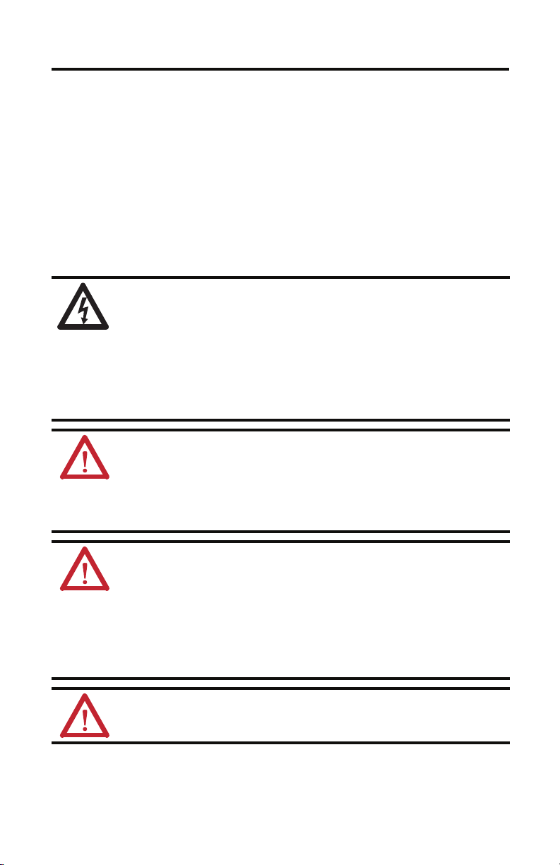
SHOCK HAZARD: To avoid the hazard of electrical shock, be sure to ground any cable providing
power at a minimum of one point. To prevent the build-up of electrical energy, factory-supplied
cables use one of these grounding techniques:
• Bond the overall shield to the connector housing.
• Make sure there is a dire ct connect ion-to-ground for each cable shield.
• Connect an exposed cable braid or a ground wire, if present, to the power cable clamp,
housing, or another suitable chassis ground.
Failure to observe these safety procedures could result in personal injury or equipment damage.
ATT EN TI ON : Arcing or unexpected motion can occur if cables are connected or disconnected while
power is applied to the IDM sy stem. Before working on an IDM system, disconnect power and wait
the full time interval as indicated in the warning on the IPIM module or verify the DC bus voltage at
the IPIM module measures less than 50V DC.
Failure to observe this precaution could result in severe bodily injury or loss of life, and damage to
the product will occur.
ATTENTION: The hybrid connectors on the IDM unit are de signed to be rotated into a fixed position
during motor installation, and remain in that position without further adjustment. Strictly limit
the applied forces and the number of times the hybrid connectors are rotated to make sure the
connectors meet the specified IP ratings.
Apply force only to the connector and cable plug. Do not apply force to the cable extending from
the cable plug. No tools, for example pliers or vise-grips, should be used to assist with the rotation
of the connector.
Failure to observe safety precautions could result in damage to the IDM unit and its components.
ATT EN TI ON : The maximum length of cabling between the IPIM and the last IDM unit in the
system must not exceed 100 m (328 ft). Also, a maximum of two extension cables may be
connected between an IDM unit and the preceding IPIM module or IDM unit.
Publication 2090-IN038B-EN-P - March 2012
Page 4

4 Kinetix 6000M Hybrid Coupler Cable
ATTENTION: The examples in this publication show the available connections, some of which may
not be appropriate for your specific installation. Refer to your system level installation instructions
or user manual for recommended wire trim lengths, and wiring examples appropriate to your
application.
Failure to observe these safety procedures could result in personal injury or damage to the motor
and equipment.
ATTENTION: Do not tightly gather or coil the excess length of a hybrid cable. Heat is generated
within a cable whenever power is applied. Always position a hybrid cable to freely dissipate heat.
A hybrid cable should not be coiled, except for temporary use when building or testing a machine.
If you temporarily coil a hybrid cable, you must also derate the cable to meet local code or follow
an authoritative directive, such as Engineering Section 310.15(C) of the NEC Handbook.
Failure to observe these safety procedures could result in personal injury or equipment damage.
Publication 2090-IN038B-EN-P - March 2012
Page 5

Kinetix 6000M Hybrid Coupler Cable 5
IMPORTANT
Limited
Bend Zone
Installation Area
300 ± 25 (12 ± 1.0)
Installation Area
300 ± 25 (12 ± 1.0)
Femal e Extens ionMale Extension
2090-CCPP8S8 shown
Overall cable length is 1 M (3.1 ft)
Dimensions are in mm (in.).
Install the Cable
Follow these steps when installing a 2090-CCPP8S8 hybrid coupler cable.
1. Verify power to the IPIM module is removed before making any connections or
disconnecting any components of the system
ATT EN TI ON : Arcing or unexpected motion can occur if cables are connected or disconnected while
power is applied to the IDM sy stem. Before working on an IDM system, disconnect power and wait
the full time interval as indicated in the warning on the IPIM module or verify the DC bus voltage at
the IPIM module measures less than 50V DC.
Failure to observe this precaution could result in severe bodily injury or loss of life, and damage to
the product will occur.
2. Before beginning any cable bend, determine the recommended installation areas, and the
clearance required from the features shown in the diagram.
Clearance from these areas should be greater than or equal to the cable diameter.
3. Keep cable bends within the bend radius listed in the Specifications on page
7.
Hybrid cables have a bend radius of twelve times the cable diameter.
4. Observe these restrictions when installing the connecting cables:
• Prevent the cable from flexing within 150 ±25 mm (6 ±1 in.) installation areas.
• Bend cables to a specific shape only in the bend zone area.
• Provide cable supports at 3m (10 ft) intervals along the cable run to reduce tension
and flexing at the connectors and other features on the cable.
5. Tighten each M23 connector approximately 45° to fully seat the contacts and secure
each connection.
The internal O-ring is self-conforming and requires a short period between each
connect/disconnect cycle to expand to full size. Let the O-ring expand for at least 60 seconds
before reconnecting a hybrid cable.
Publication 2090-IN038B-EN-P - March 2012
Page 6

6 Kinetix 6000M Hybrid Coupler Cable
A
B
C
D
GND
4
5
6
7
8
9
10
A
B
C
D
GND
4
5
6
7
8
9
10
Brown
GND
78
910
6
5
4
1
3
2
DA
BC
Grey
Blue
White/Blue
Brown
White/Brown
White/Pink
Pink
Green
Orange
Viol et
Yellow
Braided Shield
Twisted Pair Shield Wire Connection
1. The braided shield connects to the cable grounding ring with a 360º connection.
(1)
2. The drain wire connects to the cable grounding ring.
(1)
(2)
Male Plug Female Plug
(2)
2090-CCPP8S8 Cable Schematic and Connector Pinouts
2
1
3
D
Publication 2090-IN038B-EN-P - March 2012
4
98710
6
GND
BC
5
A
Page 7

Kinetix 6000M Hybrid Coupler Cable 7
Specifications
Additional specifications for each cable are available in the Kinetix® Motion Accessories
Technical Data, publication GMC-TD004.
Attribute 2090-CCPP8S8
Wire si zes:
DC Bus (650V DC)
Control Power (42V DC)
Communication (CAN, Safety, SYSOK)
(1)
Diameter of cable
Bend radius of cable 170 mm (6.70 in.)
O-ring expansion period One minute between
(1) Cable diameter tolerance is ± 0.13 mm (0.005in.).
12 AWG
16 AWG
22 AWG
14.2 mm (0.56 in.)
disconnection and reconnection.
Additional Resources
These documents contain additional information concerning related products from Rockwell
Automation.
Resource Description
Kinetix 6000M Integrated Drive-Motor User Manual,
publication 2094-UM003
Kinetix 6000M Integrated Drive-Motor Installation
Instructions, publication MDF-IN001
Allen-Bradley Industrial Automation Glossary, publication
AG-7.1
System Design for Control of Electrical Noise Reference
Manual, publication GMC-RM001
Kinetix Rotary Motion Specifications Technical Data,
publication GMC-TD001
Kinetix Motion Accessories Technical Data, publication
GMC-TD004
You can view or download publications at http://www.rockwellautomation.com/literature
Information on installing, configuring, starting, and
troubleshooting a Kinetix 6000M integrated drive-motor
system.
Information on the installation of your Kinetix 6000M
integrated drive-motor unit.
A glossary of industrial automation terms and abbreviations.
Information, examples, and techniques designed to minimize
system failures caused by electrical nois e.
Catalog numbers and product specifications, including
performance, environmental, certifications, load force, and
dimension drawings for Allen-Bradley rotary products.
Catalog numbers and product specifications, including
performance, environmental, certifications, and dimension
drawings for Allen-Bradley accessories.
.
To order paper copies of technical documentation, contact your Allen-Bradley® distributor or
Rockwell Automation® sales representative.
Publication 2090-IN038B-EN-P - March 2012
Page 8

Rockwell Automation Support
Rockwell Automation provides tec hnical information on the Web to assist you in using its products.
At http://www.rockwellautomation.com/support
links to software service packs, and a MySupport feature that you can customize to make the best use of these tools. You can also visit
our Knowledgebase at http://www.rockwellautomation.com/knowledgebase
forums, software updates, and to sign up for product notification updates.
, you can find technical manuals, technical and application notes, sample code and
for FAQs, technical information, support chat and
For an additional level of technical phone support for installation, configuration and troubleshooting, we offer TechConnect
programs. For more information, contact your local distributor or Rockwell Automation representative, or visit
http://www.rockwellautomation.com/support/
.
® support
Installation Assistance
If you experience a problem within the first 24 hours of installation, please review the information that's contained in this manual.
You can also contact a special Customer Support number for initial help in getting your product up and running.
United States or Canada 1.440.646.3434
Outside United States or
Canada
Use the Wor ldwi de Loc ator
http://www.rockwellautomation.com/support/americas/phone_en.html
Rockwell Automation representative.
at
, or contact your local
New Product Satisfaction Return
Rockwell Automation tests all o f its products to ensure that they are fully operational when shipped from the manufacturing facility.
However, if your product is not functioning and needs to be returned, follow these procedures.
United States
Outside United States Please contact your local Rockwell Automation representative for the return procedure.
Contact your distributor. You must provide a Customer Support case number (call the phone number
above to obtain one) to your distributor to complete the return process.
Documentation Feedback
Your comments will help us serve your documentation needs better. If you have any suggestions on how to improve this document,
complete this form, publication RA-DU002
, available at http://www.rockwellautomation.com/literature/.
Allen-Bradley, Kinetix, Rockwell Automation, and TechConnect are trademarks of Rockwell Automation, Inc.
Trademarks not belonging to R ockwell Automation are property of their respective companies.
Publication 2090-IN038B-EN-P - March 2012 PN-143965
Supersedes Publication 2090-IN038A-EN-P - February 2012 Copyright © 2012 Rockwell Automation, Inc. All rights reserved. Printed in the U.S.A.
 Loading...