

Page 1

Quick Start
Drives and Motion Accelerator Toolkit
Page 2

Important User Information
IMPORTANT
Read this document and the documents listed in the additional resources section about installation, configuration, and
operation of this equipment before you install, configure, operate, or maintain this product. Users are required to
familiarize themselves with installation and wiring instructions in addition to requirements of all applicable codes, laws,
and standards.
Activities including installation, adjustments, putting into service, use, assembly, disassembly, and maintenance are required
to be carried out by suitably trained personnel in accordance with applicable code of practice.
If this equipment is used in a manner not specified by the manufacturer, the protection provided by the equipment may be
impaired.
In no event will Rockwell Automation, Inc. be responsible or liable for indirect or consequential damages resulting from the
use or application of this equipment.
The examples and diagrams in this manual are included solely for illustrative purposes. Because of the many variables and
requirements associated with any particular installation, Rockwell Automation, Inc. cannot assume responsibility or
liability for actual use based on the examples and diagrams.
No patent liability is assumed by Rockwell Automation, Inc. with respect to use of information, circuits, equipment, or
software described in this manual.
Reproduction of the contents of this manual, in whole or in part, without written permission of Rockwell Automation,
Inc., is prohibited.
Throughout this manual, when necessary, we use notes to make you aware of safety considerations.
WARNING: Identifies information about practices or circumstances that can cause an explosion in a hazardous environment,
which may lead to personal injury or death, property damage, or economic loss.
ATTENTION: Identifies information about practices or circumstances that can lead to personal injury or death, property
damage, or economic loss. Attentions help you identify a hazard, avoid a hazard, and recognize the consequence.
Identifies information that is critical for successful application and understanding of the product.
Labels may also be on or inside the equipment to provide specific precautions.
SHOCK HAZARD: Labels may be on or inside the equipment, for example, a drive or motor, to alert people that dangerous
voltage may be present.
BURN HAZARD: Labels may be on or inside the equipment, for example, a drive or motor, to alert people that surfaces may
reach dangerous temperatures.
ARC FLASH HAZARD: Labels may be on or inside the equipment, for example, a motor control center, to alert people to
potential Arc Flash. Arc Flash will cause severe injury or death. Wear proper Personal Protective Equipment (PPE). Follow ALL
Regulatory requirements for safe work practices and for Personal Protective Equipment (PPE).
Allen-Bradley, CompactLogix, ControlFLA SH, ControlLogix, DPI, DriveExplorer, DriveTools, Explorer, FactoryTalk, GuardLogix, HPK- Series, Integrated Architecture, Kinetix, LDC-Series, LDL-Series, Lo gix5000,
MP-Series, PanelView, PowerFlex, ProposalWorks, RDD-Series, Rockwell Automation, Rockwell Software, RSLogix, R SLinx, SCANport, SMC, Stratix , Studio 5000, TL-S eries, and Ultra are trademarks of
Rockwell Automation, Inc.
Trademarks not belonging to Rockwell Automation are property of their respective companies.
Page 3

Follow this path to complete your Drives and Motion application.
3
00
Chapter 3
System Layout and Wiring
Chapter 1
Initial System Configuration
Using the DMAT Wizard
Chapter 4
Logic Configuration
Chapter 7
System Application Guide
Chapter 5
Fac toryTalk View ME Configuration
Chapter 6
System
Commissioning
Chapter 2
Bill of Materials Completion
Assembly
Packaging
POWERFLEX 4
AC DRIVE
Where to Start
Servo Drive
USER PROTECTED
XXXVAC SUPPLY
MAINS DISCONNECT
PROTECTION
XXAMPS
FILTERED POWER
DRIVE
PROTECTION
Motion System Application Guide
00
755
Chapter 7
RESETTING
FIELD SIDE
MOTOR_01
MOTOR
RESET
The machine can go from any state in the shaded box to STOPPING.
START
STOP
IDLE
(enabled)
STOPPING
STOPPED
(disabled)
STARTING
The machine can go from any state
in the solid box to ABORTING.
CLEARING
CLEAR
RUNNING
ABORT
ABORTING
ABORTED
Rockwell Automation Publication IASIMP-QS019E-EN-P - August 2013 3
Page 4

Where to Start
Notes:
4 Rockwell Automation Publication IASIMP-QS019E-EN-P - August 2013
Page 5

Summary of Changes
This manual contains new and updated information.
New and Updated Information
This is a minor revision that reflects changes in the DMAT Wizard.
As a result, the Module Definitions example dialog box for PowerFlex®
750-Series datalinks has changed. Refer to page 283 see the new dialog
box.
Rockwell Automation Publication IASIMP-QS019E-EN-P - August 2013 5
Page 6

Summary of Changes
Notes:
6 Rockwell Automation Publication IASIMP-QS019E-EN-P - August 2013
Page 7

Table of Contents
Preface
About this Publication . . . . . . . . . . . . . . . . . . . . . . . . . . . . . . . . . . . . . . . . . . . 13
Conventions. . . . . . . . . . . . . . . . . . . . . . . . . . . . . . . . . . . . . . . . . . . . . . . . . . . . . 14
Required Software . . . . . . . . . . . . . . . . . . . . . . . . . . . . . . . . . . . . . . . . . . . . . . . 14
Studio 5000 Environment . . . . . . . . . . . . . . . . . . . . . . . . . . . . . . . . . . . . . . . . 15
Additional Resources . . . . . . . . . . . . . . . . . . . . . . . . . . . . . . . . . . . . . . . . . . . . . 15
Chapter 1
Initial System Configuration Using
the DMAT Wizard
Before You Begin . . . . . . . . . . . . . . . . . . . . . . . . . . . . . . . . . . . . . . . . . . . . . . . . 18
What You Need . . . . . . . . . . . . . . . . . . . . . . . . . . . . . . . . . . . . . . . . . . . . . . . . . 18
Follow These Steps. . . . . . . . . . . . . . . . . . . . . . . . . . . . . . . . . . . . . . . . . . . . . . . 18
Review the DMAT Wizard . . . . . . . . . . . . . . . . . . . . . . . . . . . . . . . . . . . . . . . 19
Simple System and Drive Configuration Entries . . . . . . . . . . . . . . . . 19
Bill of Material Output . . . . . . . . . . . . . . . . . . . . . . . . . . . . . . . . . . . . . . . 19
System Drawing Set Output. . . . . . . . . . . . . . . . . . . . . . . . . . . . . . . . . . . 20
Project File Output . . . . . . . . . . . . . . . . . . . . . . . . . . . . . . . . . . . . . . . . . . 21
FactoryTalk View Me Project File Output . . . . . . . . . . . . . . . . . . . . . 22
Review Other System Selection and Configuration Tools. . . . . . . . . . . . 23
Motion Analyzer Software . . . . . . . . . . . . . . . . . . . . . . . . . . . . . . . . . . . . 23
Engineering Assistant Software . . . . . . . . . . . . . . . . . . . . . . . . . . . . . . . . 24
Product Selection Toolbox . . . . . . . . . . . . . . . . . . . . . . . . . . . . . . . . . . . . 25
Install Other System Selection and Configuration Tools . . . . . . . . . . . . 26
Install Motion Analyzer Software . . . . . . . . . . . . . . . . . . . . . . . . . . . . . . 26
Install Engineering Assistant Software. . . . . . . . . . . . . . . . . . . . . . . . . . 26
Install Product Selection Toolbox. . . . . . . . . . . . . . . . . . . . . . . . . . . . . . 27
Run the DMAT Wizard . . . . . . . . . . . . . . . . . . . . . . . . . . . . . . . . . . . . . . . . . . 28
Launch the DMAT Wizard . . . . . . . . . . . . . . . . . . . . . . . . . . . . . . . . . . . 28
Edit the DMAT Wizard Configuration . . . . . . . . . . . . . . . . . . . . . . . . 31
Bill of Materials Completion
System Layout and Wiring
Chapter 2
Before You Begin . . . . . . . . . . . . . . . . . . . . . . . . . . . . . . . . . . . . . . . . . . . . . . . . 37
What You Need . . . . . . . . . . . . . . . . . . . . . . . . . . . . . . . . . . . . . . . . . . . . . . . . . 37
Follow These Steps. . . . . . . . . . . . . . . . . . . . . . . . . . . . . . . . . . . . . . . . . . . . . . . 38
Import the Initial Project BOM File . . . . . . . . . . . . . . . . . . . . . . . . . . . . . . . 38
Edit Your Project BOM File . . . . . . . . . . . . . . . . . . . . . . . . . . . . . . . . . . . . . . 40
Chapter 3
Before You Begin . . . . . . . . . . . . . . . . . . . . . . . . . . . . . . . . . . . . . . . . . . . . . . . . 48
What You Need . . . . . . . . . . . . . . . . . . . . . . . . . . . . . . . . . . . . . . . . . . . . . . . . . 48
Follow These Steps. . . . . . . . . . . . . . . . . . . . . . . . . . . . . . . . . . . . . . . . . . . . . . . 49
Create a New Project . . . . . . . . . . . . . . . . . . . . . . . . . . . . . . . . . . . . . . . . . . . . . 50
Edit Power Drawings . . . . . . . . . . . . . . . . . . . . . . . . . . . . . . . . . . . . . . . . . . . . . 51
Edit Drive, Controller, and Safety I/O Drawings . . . . . . . . . . . . . . . . . . . 56
Edit System Communication Drawings . . . . . . . . . . . . . . . . . . . . . . . . . . . . 61
Rockwell Automation Publication IASIMP-QS019E-EN-P - August 2013 7
Page 8

Table of Contents
Logic Configuration
Edit System Layout Drawings . . . . . . . . . . . . . . . . . . . . . . . . . . . . . . . . . . . . . 62
Chapter 4
Before You Begin. . . . . . . . . . . . . . . . . . . . . . . . . . . . . . . . . . . . . . . . . . . . . . . . . 72
What You Need. . . . . . . . . . . . . . . . . . . . . . . . . . . . . . . . . . . . . . . . . . . . . . . . . . 72
Follow These Steps . . . . . . . . . . . . . . . . . . . . . . . . . . . . . . . . . . . . . . . . . . . . . . . 73
Import the Preconfigured Logix Designer Project . . . . . . . . . . . . . . . . . . . 74
Complete Drive and Motor Configuration . . . . . . . . . . . . . . . . . . . . . . . . . 76
Setting Drive Motor Ratings. . . . . . . . . . . . . . . . . . . . . . . . . . . . . . . . . . . 76
Set String Tag Names for Alarm History Faceplate . . . . . . . . . . . . . . . . . . 77
Set Visible Rows for Equipment Status Faceplate. . . . . . . . . . . . . . . . . . . . 79
Set Visible Rows for Equipment Status Faceplate for
Energy Monitoring . . . . . . . . . . . . . . . . . . . . . . . . . . . . . . . . . . . . . . . . . . . 80
Set MSG Path in the E3 Plus Energy Monitoring Routine. . . . . . . . 81
Create Specific Application Logic. . . . . . . . . . . . . . . . . . . . . . . . . . . . . . . . . . 82
Application Code Logic Template Overview. . . . . . . . . . . . . . . . . . . . 82
Application Logic Creation Steps Using Application
Logic Examples . . . . . . . . . . . . . . . . . . . . . . . . . . . . . . . . . . . . . . . . . . . . . . . 88
Application Logic Creation Steps Using Template . . . . . . . . . . . . . . 99
Verify and Save the Project File . . . . . . . . . . . . . . . . . . . . . . . . . . . . . . . . . . . . 99
FactoryTalk View ME Configuration
Chapter 5
Before You Begin. . . . . . . . . . . . . . . . . . . . . . . . . . . . . . . . . . . . . . . . . . . . . . . . 103
What You Need. . . . . . . . . . . . . . . . . . . . . . . . . . . . . . . . . . . . . . . . . . . . . . . . . 103
Follow These Steps . . . . . . . . . . . . . . . . . . . . . . . . . . . . . . . . . . . . . . . . . . . . . . 104
Design From a Preconfigured HMI Application File . . . . . . . . . . . . . . . 104
Open FactoryTalk View ME Configuration Guide . . . . . . . . . . . . . 105
Restore and Open a Preconfigured HMI Application . . . . . . . . . . . 106
Delete Unused Displays . . . . . . . . . . . . . . . . . . . . . . . . . . . . . . . . . . . . . . 109
Delete Unused Parameter Files. . . . . . . . . . . . . . . . . . . . . . . . . . . . . . . . 110
Configure Parameter Files . . . . . . . . . . . . . . . . . . . . . . . . . . . . . . . . . . . . 111
Delete Unused Alarm Triggers and Tags. . . . . . . . . . . . . . . . . . . . . . . 115
Design From an Existing HMI Application File. . . . . . . . . . . . . . . . . . . . 117
Open Your Existing HMI Application File and Add Displays . . . 117
Add Parameter Files . . . . . . . . . . . . . . . . . . . . . . . . . . . . . . . . . . . . . . . . . 120
Configure Parameter Files . . . . . . . . . . . . . . . . . . . . . . . . . . . . . . . . . . . . 122
Import Alarm Setup File . . . . . . . . . . . . . . . . . . . . . . . . . . . . . . . . . . . . . 126
Delete Unused Alarm Triggers. . . . . . . . . . . . . . . . . . . . . . . . . . . . . . . . 128
Import and Edit Alarm Tags. . . . . . . . . . . . . . . . . . . . . . . . . . . . . . . . . . 129
Configure Goto Display Buttons on Startup Display . . . . . . . . . . . . . . . 132
Configure Equipment Status Faceplate Display . . . . . . . . . . . . . . . . . . . . 138
Add the Equipment Status Faceplate Display. . . . . . . . . . . . . . . . . . . 139
Add the ME_Equipment_Parameter File . . . . . . . . . . . . . . . . . . . . . . 140
Configure Goto Buttons on the Equipment Status Faceplate . . . . 142
Configure Additional Device Value Columns . . . . . . . . . . . . . . . . . . 144
Configure Equipment Status Faceplate for Energy Monitoring . . 145
8 Rockwell Automation Publication IASIMP-QS019E-EN-P - August 2013
Page 9

Chapter 6
Table of Contents
System Commissioning
Before You Begin . . . . . . . . . . . . . . . . . . . . . . . . . . . . . . . . . . . . . . . . . . . . . . . 147
What You Need . . . . . . . . . . . . . . . . . . . . . . . . . . . . . . . . . . . . . . . . . . . . . . . . 147
Follow These Steps. . . . . . . . . . . . . . . . . . . . . . . . . . . . . . . . . . . . . . . . . . . . . . 148
Download Applications . . . . . . . . . . . . . . . . . . . . . . . . . . . . . . . . . . . . . . . . . 148
Download Logix Designer Project . . . . . . . . . . . . . . . . . . . . . . . . . . . . 148
Configure and Download FactoryTalk Project to
PanelView Plus Terminal . . . . . . . . . . . . . . . . . . . . . . . . . . . . . . . . . . . . 150
Commissioning Devices . . . . . . . . . . . . . . . . . . . . . . . . . . . . . . . . . . . . . . . . . 155
Commissioning CIP Motion Drives . . . . . . . . . . . . . . . . . . . . . . . . . . 155
Commissioning Sercos Drives . . . . . . . . . . . . . . . . . . . . . . . . . . . . . . . . 158
Commissioning PowerFlex 7-class Drives. . . . . . . . . . . . . . . . . . . . . . 159
Commissioning PowerFlex 5-class Drives. . . . . . . . . . . . . . . . . . . . . . 161
Commissioning PowerFlex 4-class Drives. . . . . . . . . . . . . . . . . . . . . . 162
Commissioning Kinetix 300 Drives . . . . . . . . . . . . . . . . . . . . . . . . . . . 163
Commissioning E3 Plus Overload Relays . . . . . . . . . . . . . . . . . . . . . . 164
Commissioning SMC-50 Soft Starter Modules . . . . . . . . . . . . . . . . 166
Commissioning Drives and Motion Systems. . . . . . . . . . . . . . . . . . . . . . . 167
Verify Network Communication . . . . . . . . . . . . . . . . . . . . . . . . . . . . . 167
Clearing Faults . . . . . . . . . . . . . . . . . . . . . . . . . . . . . . . . . . . . . . . . . . . . . . 168
Operator (manual) Control . . . . . . . . . . . . . . . . . . . . . . . . . . . . . . . . . . 169
Program (automatic) Control . . . . . . . . . . . . . . . . . . . . . . . . . . . . . . . . 169
System Application Guide
Chapter 7
Before You Begin . . . . . . . . . . . . . . . . . . . . . . . . . . . . . . . . . . . . . . . . . . . . . . . 171
What You Need . . . . . . . . . . . . . . . . . . . . . . . . . . . . . . . . . . . . . . . . . . . . . . . . 171
Follow These Steps. . . . . . . . . . . . . . . . . . . . . . . . . . . . . . . . . . . . . . . . . . . . . . 172
Machine Startup Faceplate. . . . . . . . . . . . . . . . . . . . . . . . . . . . . . . . . . . . . . . 173
Machine Status. . . . . . . . . . . . . . . . . . . . . . . . . . . . . . . . . . . . . . . . . . . . . . 173
Machine Control. . . . . . . . . . . . . . . . . . . . . . . . . . . . . . . . . . . . . . . . . . . . 175
Program/Operator Mode . . . . . . . . . . . . . . . . . . . . . . . . . . . . . . . . . . . . 175
State Diagram Faceplate Display . . . . . . . . . . . . . . . . . . . . . . . . . . . . . . 176
Motion Drives Faceplates . . . . . . . . . . . . . . . . . . . . . . . . . . . . . . . . . . . . . . . . 177
Home View. . . . . . . . . . . . . . . . . . . . . . . . . . . . . . . . . . . . . . . . . . . . . . . . . 177
Axis Status Views. . . . . . . . . . . . . . . . . . . . . . . . . . . . . . . . . . . . . . . . . . . . 178
Axis Control Views. . . . . . . . . . . . . . . . . . . . . . . . . . . . . . . . . . . . . . . . . . 179
Fault Indication View. . . . . . . . . . . . . . . . . . . . . . . . . . . . . . . . . . . . . . . . 181
Fault Diagnostic Views . . . . . . . . . . . . . . . . . . . . . . . . . . . . . . . . . . . . . . 182
Configuration View . . . . . . . . . . . . . . . . . . . . . . . . . . . . . . . . . . . . . . . . . 183
Trend Views . . . . . . . . . . . . . . . . . . . . . . . . . . . . . . . . . . . . . . . . . . . . . . . . 183
PowerFlex Drives Faceplates . . . . . . . . . . . . . . . . . . . . . . . . . . . . . . . . . . . . . 185
Home View. . . . . . . . . . . . . . . . . . . . . . . . . . . . . . . . . . . . . . . . . . . . . . . . . 185
Control View . . . . . . . . . . . . . . . . . . . . . . . . . . . . . . . . . . . . . . . . . . . . . . . 186
Fault Indication View. . . . . . . . . . . . . . . . . . . . . . . . . . . . . . . . . . . . . . . . 186
Fault Diagnostic Views . . . . . . . . . . . . . . . . . . . . . . . . . . . . . . . . . . . . . . 187
Configuration Views . . . . . . . . . . . . . . . . . . . . . . . . . . . . . . . . . . . . . . . . 187
Rockwell Automation Publication IASIMP-QS019E-EN-P - August 2013 9
Page 10

Table of Contents
Trend Views . . . . . . . . . . . . . . . . . . . . . . . . . . . . . . . . . . . . . . . . . . . . . . . . 189
Energy Status Views. . . . . . . . . . . . . . . . . . . . . . . . . . . . . . . . . . . . . . . . . . 191
Online Help Views . . . . . . . . . . . . . . . . . . . . . . . . . . . . . . . . . . . . . . . . . . 192
E3 Plus Overload Relay Faceplates . . . . . . . . . . . . . . . . . . . . . . . . . . . . . . . . 192
Home/Control View . . . . . . . . . . . . . . . . . . . . . . . . . . . . . . . . . . . . . . . . 192
Fault Indication View . . . . . . . . . . . . . . . . . . . . . . . . . . . . . . . . . . . . . . . . 193
Fault Diagnostic Views. . . . . . . . . . . . . . . . . . . . . . . . . . . . . . . . . . . . . . . 194
Configuration View. . . . . . . . . . . . . . . . . . . . . . . . . . . . . . . . . . . . . . . . . . 195
Online Help Views . . . . . . . . . . . . . . . . . . . . . . . . . . . . . . . . . . . . . . . . . . 195
Energy Status Views. . . . . . . . . . . . . . . . . . . . . . . . . . . . . . . . . . . . . . . . . . 196
SMC-50 Soft Starter Faceplates. . . . . . . . . . . . . . . . . . . . . . . . . . . . . . . . . . . 196
Home/Control View . . . . . . . . . . . . . . . . . . . . . . . . . . . . . . . . . . . . . . . . 196
Fault Indication View . . . . . . . . . . . . . . . . . . . . . . . . . . . . . . . . . . . . . . . . 197
Fault Diagnostic Views. . . . . . . . . . . . . . . . . . . . . . . . . . . . . . . . . . . . . . . 198
Configuration View. . . . . . . . . . . . . . . . . . . . . . . . . . . . . . . . . . . . . . . . . . 199
Online Help Views . . . . . . . . . . . . . . . . . . . . . . . . . . . . . . . . . . . . . . . . . . 199
Energy Status Views. . . . . . . . . . . . . . . . . . . . . . . . . . . . . . . . . . . . . . . . . . 200
Equipment Status Display Overview . . . . . . . . . . . . . . . . . . . . . . . . . . . . . . 201
Equipment Status Display for Energy Overview . . . . . . . . . . . . . . . . 202
Alarm History Display Overview . . . . . . . . . . . . . . . . . . . . . . . . . . . . . . . . . 202
Logic Program Overview
Logic Module Customization
Appendix A
Machine/Application/Device Module Relationship . . . . . . . . . . . . . . . . 204
Module Routine Overview . . . . . . . . . . . . . . . . . . . . . . . . . . . . . . . . . . . . . . . 205
Machine Module . . . . . . . . . . . . . . . . . . . . . . . . . . . . . . . . . . . . . . . . . . . . . . . . 208
Machine States . . . . . . . . . . . . . . . . . . . . . . . . . . . . . . . . . . . . . . . . . . . . . . 208
Machine Control Module Tags . . . . . . . . . . . . . . . . . . . . . . . . . . . . . . . 210
Device and Application Status Rung Tags and Logic. . . . . . . . . . . . 211
Application Modules . . . . . . . . . . . . . . . . . . . . . . . . . . . . . . . . . . . . . . . . . . . . 214
Device Modules . . . . . . . . . . . . . . . . . . . . . . . . . . . . . . . . . . . . . . . . . . . . . . . . . 215
Device Module Tags . . . . . . . . . . . . . . . . . . . . . . . . . . . . . . . . . . . . . . . . . 215
Device Module Control Logic Example. . . . . . . . . . . . . . . . . . . . . . . . 217
Appendix B
Machine State Customization . . . . . . . . . . . . . . . . . . . . . . . . . . . . . . . . . . . . 219
Tag and Logic Modification Recommendations . . . . . . . . . . . . . . . . 222
State Display Tag Modifications . . . . . . . . . . . . . . . . . . . . . . . . . . . . . . 223
Bypass Idle State Modifications . . . . . . . . . . . . . . . . . . . . . . . . . . . . . . . 224
Module Fault Customization. . . . . . . . . . . . . . . . . . . . . . . . . . . . . . . . . . . . . 225
Alarm History Faceplate Logic Modification . . . . . . . . . . . . . . . . . . . . . . 227
Coordinated Reset Customization . . . . . . . . . . . . . . . . . . . . . . . . . . . . . . . . 228
Appendix C
Add Other Devices to the Equipment
Status Faceplate
10 Rockwell Automation Publication IASIMP-QS019E-EN-P - August 2013
Add Devices to the Equipment Status Faceplate. . . . . . . . . . . . . . . . . . . . 229
Add Optional Faceplate Views . . . . . . . . . . . . . . . . . . . . . . . . . . . . . . . . . . . 232
Page 11

Appendix D
Table of Contents
Logix Designer Communication and
Controller Configuration
Create and Add BOM Device Modules
Without the DMAT Wizard
Assemble Project Drawing Set
Without the DMAT Wizard
Configure Personal Computer Communication Properties . . . . . . . . . 235
Configure the EtherNet/IP Driver . . . . . . . . . . . . . . . . . . . . . . . . . . . . . . . 237
Configure the Logix5000 Controller . . . . . . . . . . . . . . . . . . . . . . . . . . . . . 238
Appendix E
Before You Begin . . . . . . . . . . . . . . . . . . . . . . . . . . . . . . . . . . . . . . . . . . . . . . . 245
What You Need . . . . . . . . . . . . . . . . . . . . . . . . . . . . . . . . . . . . . . . . . . . . . . . . 245
Follow These Steps. . . . . . . . . . . . . . . . . . . . . . . . . . . . . . . . . . . . . . . . . . . . . . 246
Select Initial BOM Files . . . . . . . . . . . . . . . . . . . . . . . . . . . . . . . . . . . . . . . . . 246
Add BOM Device Modules . . . . . . . . . . . . . . . . . . . . . . . . . . . . . . . . . . . . . . 248
Appendix F
Before You Begin . . . . . . . . . . . . . . . . . . . . . . . . . . . . . . . . . . . . . . . . . . . . . . . 255
What You Need . . . . . . . . . . . . . . . . . . . . . . . . . . . . . . . . . . . . . . . . . . . . . . . . 255
Follow These Steps. . . . . . . . . . . . . . . . . . . . . . . . . . . . . . . . . . . . . . . . . . . . . . 256
Select Drive Power Drawings. . . . . . . . . . . . . . . . . . . . . . . . . . . . . . . . . . . . . 257
Select Controller Power Drawings . . . . . . . . . . . . . . . . . . . . . . . . . . . . . . . . 259
Select External Safety Relay Option Drawings . . . . . . . . . . . . . . . . . . . . . 260
Select Drive I/O Drawings. . . . . . . . . . . . . . . . . . . . . . . . . . . . . . . . . . . . . . . 261
Select Controller I/O Drawings . . . . . . . . . . . . . . . . . . . . . . . . . . . . . . . . . . 262
Select System Communication Drawings. . . . . . . . . . . . . . . . . . . . . . . . . . 264
Select System Layout Drawings. . . . . . . . . . . . . . . . . . . . . . . . . . . . . . . . . . . 265
Select Power and Control Component Layout Footprint Drawings . 267
Controller, Network, and Device
Configuration
Without the DMAT Wizard
Appendix G
Before You Begin . . . . . . . . . . . . . . . . . . . . . . . . . . . . . . . . . . . . . . . . . . . . . . . 269
What You Need . . . . . . . . . . . . . . . . . . . . . . . . . . . . . . . . . . . . . . . . . . . . . . . . 269
Follow These Steps. . . . . . . . . . . . . . . . . . . . . . . . . . . . . . . . . . . . . . . . . . . . . . 270
Controller and Network Configuration. . . . . . . . . . . . . . . . . . . . . . . . . . . 271
Create a New Project File . . . . . . . . . . . . . . . . . . . . . . . . . . . . . . . . . . . . 271
Configure the Ethernet Module . . . . . . . . . . . . . . . . . . . . . . . . . . . . . . 273
Configure the Sercos Module. . . . . . . . . . . . . . . . . . . . . . . . . . . . . . . . . 274
Save the Project File . . . . . . . . . . . . . . . . . . . . . . . . . . . . . . . . . . . . . . . . . 276
Device Configuration . . . . . . . . . . . . . . . . . . . . . . . . . . . . . . . . . . . . . . . . . . . 277
PowerFlex Drive Configuration . . . . . . . . . . . . . . . . . . . . . . . . . . . . . . . . . . 277
Update PowerFlex Add-On Profiles. . . . . . . . . . . . . . . . . . . . . . . . . . . 278
PowerFlex 525 Add-On Profiles . . . . . . . . . . . . . . . . . . . . . . . . . . . . . . 280
Add and Configure PowerFlex Drives . . . . . . . . . . . . . . . . . . . . . . . . . 281
Set PowerFlex Drive Parameters . . . . . . . . . . . . . . . . . . . . . . . . . . . . . . 286
Download Drive Parameters . . . . . . . . . . . . . . . . . . . . . . . . . . . . . . . . . 290
CIP Motion Drive Configuration . . . . . . . . . . . . . . . . . . . . . . . . . . . . . . . . 293
Configure CIP Motion Drive Modules. . . . . . . . . . . . . . . . . . . . . . . . 293
Configure the Motion Group . . . . . . . . . . . . . . . . . . . . . . . . . . . . . . . . 300
Configure Axis Properties. . . . . . . . . . . . . . . . . . . . . . . . . . . . . . . . . . . . 301
Rockwell Automation Publication IASIMP-QS019E-EN-P - August 2013 11
Page 12

Table of Contents
Sercos Motion Drive Configuration. . . . . . . . . . . . . . . . . . . . . . . . . . . . . . . 304
Configure Sercos Drive Modules . . . . . . . . . . . . . . . . . . . . . . . . . . . . . . 304
Configure the Motion Group. . . . . . . . . . . . . . . . . . . . . . . . . . . . . . . . . 307
Configure Axis Properties . . . . . . . . . . . . . . . . . . . . . . . . . . . . . . . . . . . . 308
Kinetix 300 Drive Configuration . . . . . . . . . . . . . . . . . . . . . . . . . . . . . . . . . 309
Update Kinetix 300 Add-On Profiles. . . . . . . . . . . . . . . . . . . . . . . . . . 310
Add Kinetix 300 Drives to Your Logix Designer Project . . . . . . . . 311
Configure Kinetix 300 Drives. . . . . . . . . . . . . . . . . . . . . . . . . . . . . . . . . 312
E3 Plus Overload Relay with Communication Auxiliary
Configuration. . . . . . . . . . . . . . . . . . . . . . . . . . . . . . . . . . . . . . . . . . . . . . . . . . . 321
Update E3 Plus Add-On Profiles. . . . . . . . . . . . . . . . . . . . . . . . . . . . . . 321
Add E3 Plus Devices to Your Logix Designer Project . . . . . . . . . . . 322
SMC-50 Soft Starter Configuration. . . . . . . . . . . . . . . . . . . . . . . . . . . . . . . 323
Update SMC-50 Add-On Profiles . . . . . . . . . . . . . . . . . . . . . . . . . . . . 323
Add SMC-50 Devices to Your Logix Designer Project . . . . . . . . . . 324
Download Soft Starter Parameters . . . . . . . . . . . . . . . . . . . . . . . . . . . . 326
Import and Configure Logic Modules. . . . . . . . . . . . . . . . . . . . . . . . . . . . . 328
Import and Configure the Machine Logic Module. . . . . . . . . . . . . . 328
Import and Configure Application Logic Modules . . . . . . . . . . . . . 332
Import and Configure Device Logic Modules . . . . . . . . . . . . . . . . . . 336
12 Rockwell Automation Publication IASIMP-QS019E-EN-P - August 2013
Page 13

Preface
IMPORTANT
About this Publication
This quick start provides step by step instructions for using the Drives and Motion Accelerator Toolkit to help
you design, install, operate, and maintain a drive system. Included are selection tools, layout and wiring drawings,
and pre-configured logic and HMI files to assist you in creating an Integrated Architecture™ solution for your
application requirements.
The instructions also show how the Drives and Motion Accelerator Toolkit (DMAT) Wizard can automate the
tasks needed to build the files used in the Integrated Architecture solution.
All of the supporting files are included on the Drives and Motion Accelerator Toolkit DVD, publication
IASIMP-SP017, including the DMAT Wizard. The DVD provides drive selection tools; CAD drawings for
panel layout and wiring; basic status, control, and diagnostic logic files; FactoryTalk® View ME and SE faceplates,
and more. For a copy of the DVD, contact your local Rockwell Automation distributor or sales representative.
With these tools and the built-in best-practices design, the system designer is free to focus on the design of their
machine control and not on design overhead tasks.
You can also download these same supporting files from the Rockwell Automation® Integrated Architecture
Tools website, http://www.ab.com/go/iatools on the Beyond Getting Started tab.
Before using this quick start and the contents of the Drives and Motion Accelerator Toolkit DVD, read the Terms and Conditions
READ ME.pdf on the DVD.
The beginning of each chapter contains the following information. Read these sections carefully before
beginning work in each chapter.
• Before You Begin - This section lists the steps that must be completed and decisions that must be made
before starting that chapter. The chapters in this quick start do not have to be completed in the order in
which they appear, but this section defines the minimum amount of preparation required before
completing the current chapter.
• What You Need - This section lists the tools that are required to complete the steps in the current chapter.
This includes, but is not limited to, hardware and software.
• Follow These Steps - This illustrates the steps in the current chapter and identifies which steps are
required to complete the examples using specific networks.
Rockwell Automation Publication IASIMP-QS019E-EN-P - August 2013 13
Page 14

Preface
Conventions
Convention Meaning Example
Used as an abbreviation for Integrated Motion on the EtherNet/IP network. This term describes
CIP Motion
Click
Double-click
Right-click Click right mouse button once (assumes cursor is positioned on object or selection). Right-click the Fieldbus Networks icon.
Drag and drop
Select Click to highlight a menu item or list choice. From the pull-down menu, choose H1-1.
Check/uncheck Click to select a checkbox option.
> Shows nested menu selections as menu name followed by menu selection. Click File>Page Setup>Options.
Expand Click the + to the left of a given item /folder to show its contents. In the H1-1 dialog box, expand FFLD.
Enter Used when you can type from the keyboard or choose from a list. Enter the catalog number of the product.
Type Used when the only option is to type from the keyboard. Type the catalog number of the product.
Press
Rockwell Automation servo drives and high-power AC drives that use CIP Motion and CIP Sync
technology from ODVA, all built on the Common Industrial Protocol (CIP) communicating over
the EtherNet/IP network. Two drive platforms that apply are Kinetix® 6500 servo drives and
PowerFlex 755 AC drives when used on the EtherNet/IP network.
Click left mouse button once (assumes cursor is positioned on object or selection). Click button
to initiate action.
Click left mouse button twice in quick succession (assumes cursor is positioned on object or
selection).
Click and hold the left mouse button on an object, move the cursor to where you want to move
the object, and release the mouse button.
Press a specific button on the PanelView™ terminal or other component with touch-screen
technology.
CIP Motion Drive Configuration
Click Browse.
Double-click the H1 icon.
Drag and drop the desired block into the Strategy
dialog box.
Check Cons ider Case if yo u want to conduc t a case-s ensitive
search.
Press Axis Control.
Required Software
Rockwell Automation Software Cat. No. Version Required For
Studio 5000™ Logix Designer application
RSLogix™ 5000
• Control FLASH™
• BOOTP/DHCP utility (EtherNet/IP)
• RSLinx® Classic
FactoryTalk View Studio for Machine Edition
• FactoryTalk Services
• RSLinx Enterprise
• RSLinx Classic
Motion Analyzer Rockwell Automation Configuration and Selection Tools
ProposalWorks™ 7.5 or later Bill of materials development
Drives and Motion Accelerator Toolkit DVD IASIMP-SP017 N/A
(1) When Kinetix 350 servo drives are used, version 20.00 or later is required.
9324-RLD300xxE
9701-VWSTMENE 5.1 or later PanelView Plus terminals
website http://www.rockwellautomation.com/en/e-tools
or ask your Rockwell Automation sales representative for the
Product Selection Toolbox DVD
21.00 or later
All Kinetix and PowerFlex drive
(1)
19.00 or later
5.2 or later Drive/motor sizing
applications
CAD files, wiring diagrams,
application files, and other
support information
14 Rockwell Automation Publication IASIMP-QS019E-EN-P - August 2013
Page 15

Preface
Studio 5000 Environment
The Studio 5000 Engineering and Design Environment combines engineering and design elements into a
common environment. The first element in the Studio 5000 environment is the Logix Designer application. The
Logix Designer application is the rebranding of RSLogix 5000 software and will continue to be the product to
program Logix5000™ controllers for discrete, process, batch, motion, safety, and drive-based solutions.
The Studio 5000 environment is the foundation for the future of Rockwell Automation engineering design tools
and capabilities. It is the one place for design engineers to develop all the elements of their control system.
Additional Resources
These documents contain additional information concerning related products from Rockwell Automation.
Resource Description
PowerFlex 4 Adjustable Frequency Drive User Manual, publication 22A-UM001
PowerFlex 40 Adjustable Frequency Drive User Manual, publication 22B-UM001
PowerFlex 40P Adjustable Frequency Drive User Manual, publication 22D-UM001
PowerFlex 70 and 70EC Adjustable Frequency Drive User Manual, publication 20A-UM001
PowerFlex 400 Adjustable Frequency Drive User Manual, publication 22C-UM001
PowerFlex 525 Adjustable Frequency AC Drive User Manual, publication 520-UM001 Provides mounting and wiring instructions for PowerFlex 525 AC drives.
PowerFlex 700 Adjustable Frequency Drive User Manual, publication 20B-UM001
PowerFlex 700H Adjustable Frequency Drive User Manual, publication 20C-PM001
PowerFlex 700S High Performance Drive, Phase II User Manual, publication 20D-UM006
PowerFlex 700S High Performance Drive, Phase I User Manual, publication 20D-UM001
PowerFlex 700 Vector Controlled AC Drives User Manual, publication 20B-UM002
PowerFlex 750 Series AC Drives User Manual, publication 750-UM001
PowerFlex Family Selection Guide, publication PFLEX-SG002
Provides mounting and wiring instruct ions for PowerFlex 4-class AC drives. Also provides
information on how to set drive parameters and troubleshoot the drive.
Provides mounting and wiring instruct ions for PowerFlex 7-class AC drives. Also provides
information on how to set drive parameters and troubleshoot the drive.
Provides drive specifications for the PowerFlex 4-class, 5-class, and 7-class AC drive
products.
Rockwell Automation Publication IASIMP-QS019E-EN-P - August 2013 15
Page 16

Preface
Resource Description
PowerFlex 70 EtherNet/IP Adapter User Manual, publication 20COMM-UM010
Provides details on how to install, configure, and use the adapter.PowerFlex 70 DeviceNet Adapter User Manual, publication 20COMM-UM002
PowerFlex 525 Embedded EtherNet/IP Adapter User Manual, publication 520COM-UM001
Kinetix 300 EtherNet/IP Indexing Drives User Manual, publication 2097-UM001
Kinetix 350 Single-axis EtherNet/IP Drives User Manual, publication 2097-UM002
Kinetix 6200 and Kinetix 6500 Modular Multi-axis Servo Drives User Manual,
publication 2094-UM002
Kinetix 6000 Multi-axis Servo Drives User Manual, publication 2094-UM001
Kinetix 6000M Integrated Drive-Motor System User Manual, publication 2094-UM003
Kinetix 2000 Multi-axis Servo Drives User Manual, publication 2093-UM001
Kinetix 7000 Multi-axis Servo Drives User Manual, publication 2099-UM001
Ultra™3000 Digital Servo Drives Installation Manual, publication 2098-IN003 Provides mounting and wiring instructions for Ultra3000 digital servo drives.
Ultra3000 Digital Servo Drives Integration Manual, publication 2098-IN005
Kinetix Motion Control Selection Guide, publication GMC-SG001
Kinetix Rotary Motion Specifications, publication GMC-TD001
Kinetix Linear Motion Specifications, publication GMC-TD002
Kinetix Servo Drives Specifications, publication GMC-TD003
Kinetix Motion Accessories Specifications, publication GMC-TD004
Kinetix 6000 and Kinetix 6200/6500 Drive Systems Design Guide, publication GMC-RM003
Kinetix 300 and Kinetix 350 Drive Systems Design Guide, publication GMC-RM004
Kinetix 2000 Drive Systems Design Guide, publication GMC-RM006
Kinetix 7000 Drive Systems Design Guide, publication GMC-RM007
Ultra3000 Drive Systems Design Guide, publication GMC-RM008
E3 and E3 Plus Solid-state Overload Relay User Manual, publication 193-UM002.
EtherNet/IP Communications Auxiliary User Manual, 193-UM014
SMC™-50 Solid-state Smart Motor Controller User Manual, publication 150-UM011. Provides mounting and installation instructions for SMC-50 soft-starter modules.
Sercos and Analog Motion Configuration and Startup User Manual, publication
MOTION-UM001
Motion Coordinate System User Manual, publication MOTION-UM002
Integrated Motion on the Ethernet/IP Network Configuration and Startup User Manual,
publication MOTION-UM003
Integrated Motion on the Ethernet/IP Network Reference Manual,
publication MOTION-RM003
Provides mounting, wiring, configuring, and troubleshooting instructions for the Kinetix
Motion Control servo drives.
Provides configuring and troubleshooting instructions for the Ultra3000 digital servo
drives.
Overview of Kinetix servo drives, motors, actuators, and motion accessories designed to
help make initial decisions for the motion control products best suited for your system
requirem ents.
Product specifications for MP-Series™ (Bulletin MPL, MPM, MPF, MPS), Kinetix 6000M
(Bulletin MDF), TL-Series™, RDD-Series™, and HPK-Series™ rotary motors.
Product specifications for Bulletin MPAS and MPMA linear stages, Bulletin MPAR, MPAI,
and TLAR electric cylinders, and LDC-Series™ and LDL-Series™ linear motors.
Product specifications for Kinetix Integrated Motion over the EtherNet/IP network,
Integrated Motion over sercos interface, EtherNet/IP networking, and component servo
drive families.
Product specifications for Bulletin 2090 motor and interface cables, low-profile
connector kits, drive power components, and other servo drive accessory items.
System design guide to determine and select the required (drive specific) drive module,
power accessory, connector kit, motor cable, and interface cable catalog numbers for
your drive and motor/actuator motion control system. Included are system performance
specifications and torque/speed curves (rotary motion) and force/velocity curves (linear
motion) for your motion application.
Provides mounting and installation instructions for E3 and E3 Plus overload relays and
Bulletin 193 EtherNet/IP communication auxiliary modules.
Information on configuring and troubleshooting your ControlLogix® and CompactLogix™
sercos interface modules.
Information to create a motion coordinate system with sercos or analog motion
modules.
Information on configuring and troubleshooting your ControlLogix and CompactLogix
EtherNet/IP network modules.
Provides descriptions of the AXIS_CIP_DRIVE attributes and Logix Designer application
Control Modes and Methods.
You can view or download publications at http://www.rockwellautomation.com/literature. To order paper
copies of technical documentation, contact your local Allen-Bradley distributor or Rockwell Automation sales
representative.
16 Rockwell Automation Publication IASIMP-QS019E-EN-P - August 2013
Page 17
Chapter 1
755
00300
Conveyor
Y-S er vo
X-Ser vo
X-Y Gantry
Kinetix 6500
Drives
Diverter
Kinetix 300
Drive
PowerFlex 753
Drive
S
e
r
v
o
M
o
t
o
r
D
r
i
v
e
n
E
l
e
c
t
r
i
c
C
y
l
i
nde
r
I
n
d
u
c
t
i
o
n
M
o
t
o
r
Assembly
Packaging
Initial System Configuration Using the DMAT Wizard
In this chapter you use the Drives and Motion Accelerator Toolkit (DMAT) Wizard to create an initial bill of
materials, assemble a system drawing set, and create a Studio 5000 Logix Designer project file with a
preconfigured controller, network, drives and initial system program logic. In addition, you are introduced to
several Rockwell Automation system configuration tools that provide assistance in sizing your motor/drive
combinations for a variety of load, transmission, and application types.
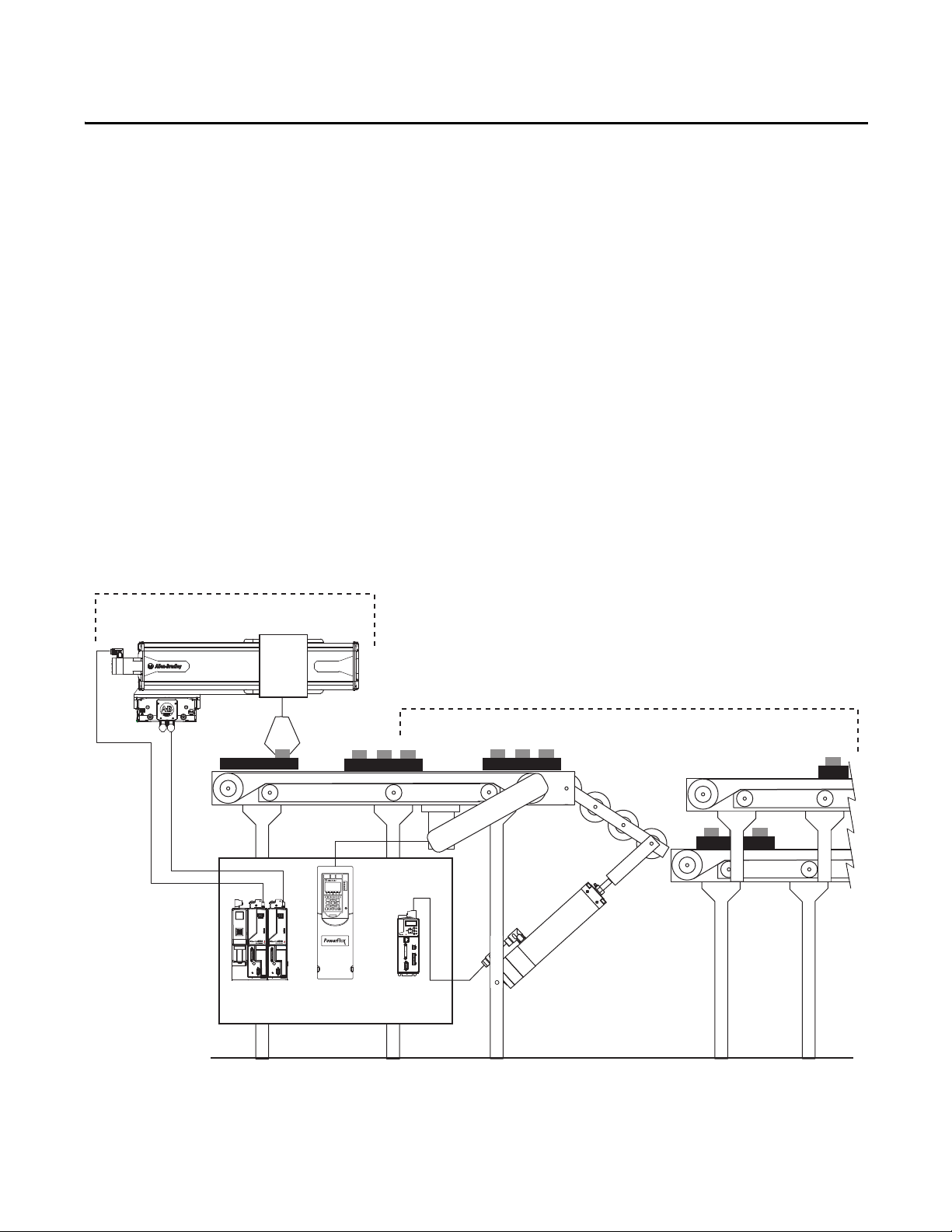
To assist you in architecture and hardware selection, the Widg-O-matic machine application is referenced in the
selection steps. Hardware selection includes all power and control equipment to support two servo drives for the
X-Y gantry, one PowerFlex drive for the conveyor, and one Kinetix 300 drive for the packaging diverter.
Widg-O-matic Machine Application Example
Rockwell Automation Publication IASIMP-QS019E-EN-P - August 2013 17
Page 18

Chapter 1 Initial System Configuration Using the DMAT Wizard
Install Other System Selection and
Configuration Tools
page 26
page 28
Review Other System Selection and
Configuration Tools
page 23
Review the DMAT Wizard
page 19
Run the DMAT Wizard
Start
Before You Begin
Collect specific application data, for example:
• System Input Voltage
• Ambient temperature and Altitude Specifications
• Transmission Type
• Motor data
• Load Data – Inertia and Cycle Profiles
• Other System Sizing Info
What You Need
• The Drives and Motion Accelerator Toolkit DVD, publication IASIMP-SP017. For a copy of the DVD,
contact your local Rockwell Automation distributor or sales representative.
• PowerFlex Family Selection Guide, publication PFLEX-SG002.
• Kinetix Motion Control Selection Guide, publication GMC-SG001.
Follow These Steps
Complete the following steps to create a bill of materials and size your drives and motion system components.
18 Rockwell Automation Publication IASIMP-QS019E-EN-P - August 2013
Page 19

Initial System Configuration Using the DMAT Wizard Chapter 1
Review the DMAT Wizard
Once you have a general idea of the overall control architecture, relative size, and type of the drives in your
system, you can use the DMAT Wizard to create a bill of material, assemble a system drawing set, and create a
Logix Designer application project file with a preconfigured controller, network, drives, and initial system
program logic. This can be accomplished in minutes by inserting simple system and drive configuration entries
and running other system selection tools as needed.
Simple System and Drive Configuration Entries
Bill of Material Output
The initial BOM files include power and control distribution equipment, control circuit protection, operator
devices, and system drives and accessories.
Rockwell Automation Publication IASIMP-QS019E-EN-P - August 2013 19
Page 20

Chapter 1 Initial System Configuration Using the DMAT Wizard
Insert images diagonal/down/partial overlap
<Wizard01.jpg, TBT>, <Wizard02.jpg, TBT>
LIM Module
AC Line Filter
Drive Power Example
Drive I/O Example
System Layout Example
System Drawing Set Output
The assembled system drawing set includes power distribution, drive power and control wiring, communication,
and system layout drawings in .dwg, .dxf, or .pdf formats.
20 Rockwell Automation Publication IASIMP-QS019E-EN-P - August 2013
Page 21

Initial System Configuration Using the DMAT Wizard Chapter 1
Project File Output
The project file includes preconfigured controller, drives, network, and machine/application/ device program
logic providing an integrated logic architecture to add your specific application logic to. The preconfigured file
saves hours in logic configuration and assembly.
MODULE COMMANDS
3
RESET
Machine Commands
Mach_Ctrl.Cmd.RESET
4
5
6
7
<WidgOmatic.Cmd.RESET>
Machine Commands
Mach_Ctrl.Cmd.STOP
<WidgOmatic.Cmd.STOP>
Machine Commands
Mach_Ctrl.Cmd.CLEAR
<WidgOmatic.Cmd.CLEAR>
Machine Commands
Mach_Ctrl.Cmd.ABORT
<WidgOmatic.Cmd.ABORT>
Module OK (NOT
Faulted)
Module.OK
<Gantry_X_Drive.OK>
/
ONS[0].5
ONS
<Gantry_X_Axis_Ctrl.Status.OK>
Module OK (NOT
<Gantry_X_Drive.OK>
Module OK (NOT
Module.OK
<Gantry_X_Drive.OK>
ONS[0].7
ONS
Servo Ready for Use
Servo_Ctrl.Status.Ready
<Gantry_X_Axis_Ctrl.Status.Ready>
STOP
STOP
CLEAR
Servo OK (NOT
Faulted)
Servo_Ctrl.Status.OK
/
Faulted)
Module.OK
ABORT
Faulted)
ONS[0].6
ONS
<Gantry_X_Axis_Ctrl.Cmd.ClearFaults>
MOV
Move
Source 1
Dest ResetSEQ[0]
FLL
Fill File
Source 0
Dest ResetSEQ[0]
Length 4
Clear Faults
Servo_Ctrl.Cmd.ClearFaults
L
FLL
Fill File
Source 0
Dest AbortSEQ[0]
Length 4
FLL
Fill File
Source 0
Dest ResetSEQ[0]
Length 4
MOV
Move
Source 1
Dest AbortSEQ[0]
NOP
0
0
(End)
Rockwell Automation Publication IASIMP-QS019E-EN-P - August 2013 21
Page 22

Chapter 1 Initial System Configuration Using the DMAT Wizard
Factory Talk View ME Configuration Guide
This guide was created based on your DMAT Wizard selections and is meant to assist you in designing your
Factory Talk View ME application using the DMAT Pre-configured HMI application files. Use this document as a
supplement to the Design From a Preconfigured HMI Application File section in Chapter 5 of the Drives and Motor
Accelerator Toolkit Quick Start guide, IASIMP-QS019A-EN-P.
This document will define specific steps to help you:
Restore and Open a Preconfigured HMI Application
Delete Unused Displays
Delete Unused Parameter Files
Configure Parameter Files
Delete Unused Alarm Triggers and Tags
Configure Goto Display Buttons on Startup Display
Configure Equipment Status Faceplate Display
Design From a Preconfigured HMI Application File
Restore and Open a Preconfigured HMI Application
1. Navigate to the Panelview Plus 1000 folder
2. Double-click the PVP1000_Application.apa archive file
Delete Unused Displays
List of Required Faceplates
[ALARM]
[DIAGNOSTICS]
[INFORMATION]
CIPMotion Faceplate
K300_Faceplate
PowerFlex_753_755_Faceplate
PVP1000_Startup_Faceplate
PVP1000_StateDiagram_Faceplate
PVP1000_AlarmHistory_Faceplate
PVP1000_EquipmentStatus_Faceplate
Delete Unused Parameter Files
List of Required Parameter Files
CIPMotion_Parameter
K300_Parameter
PF_Parameter
Startup_Parameter
StateDiagram_Parameter
EquipmentStatus_Parameter
FactoryTalk View Me Project File Output
The FactoryTalk View Me ConfigurationGuide folder contains two files. The FactoryTalk View Me (.apa) file
contains the basic screens and parameters needed for a DMAT Wizard application. The folder also includes a
Word document with custom instructions on how to adopt the example file to your application drive set and
prepare it to add any additional screens.
22 Rockwell Automation Publication IASIMP-QS019E-EN-P - August 2013
Page 23

Initial System Configuration Using the DMAT Wizard Chapter 1
Review Other System Selection and Configuration Tools
Rockwell Automation provides a variety of other system selection and configuration tools.
Motion Analyzer Software
Motion Analyzer software is a comprehensive standard-drives and motion-control application sizing tool used
for analysis, optimization, selection, and validation. Motion Analyzer software includes configuration of load
types, profiles, and mechanisms for a variety of applications.
Load Type and Data
Mechanism Type and Data
Rockwell Automation Publication IASIMP-QS019E-EN-P - August 2013 23
Page 24

Chapter 1 Initial System Configuration Using the DMAT Wizard
Profile Data
Solution Options
Engineering Assistant Software
Engineering Assistant software provides inertia, power/
torque, braking, and other application specific calculators and
formulas to assist you in sizing the motor, drive, and
transmission for your application. Use this software as a
supplement to Motion Analyzer.
24 Rockwell Automation Publication IASIMP-QS019E-EN-P - August 2013
Page 25

Product Selection Toolbox
The Rockwell Automation Product Selection Toolbox
(PST) offers a complete suite of user tools for product
selection and configuration across produc t lines from
project conception through final design. From push
buttons to drives to motor control centers and fully
networked control systems, you’ll find the product
information and configuration assistance you need to
help you and your customers succeed with Rockwell
Automation.
• Provides access to information on a broad range of
Allen-Bradley® products and services
• Easy product selec tion interface to make it a snap to
determine the exact catalog numbers for the item
you need
• Access to current list pricing, and a comprehensive
supplemental product information list
• Contains features, such as product selection wizards,
agreement pricing, a spare parts generator, and the
ability to separate par t numbers to see what
Rockwell Automation components comprise them
• All of these features and more can help you select
the correct product based on your requirements and
give your customers the information they need fast
• Lets you quickly develop Logix/NetLinx control
system configurations with BOM and reports
• Integration with configurator allows configuration
of PowerFlex drives and ArmorStart motor
controllers
• Motion control drive/motor combinations and
accessories can be added through links to Motion
Analyzer software
• New Ethernet capabilities include Stratix™ switches
and physical media with enhanced graphical views
• IAB output can be easily exported to ProposalWorks
to take advantage of extended proposal generation
features, and supplementary data
Product Selection & System Design Tools
• Assists the user in selecting correct motor for application, proper drive, and gearbox
(if required)
• Effective optimization capabilities allow user to get the most out of the selected
motor and drive combination
• Allows users to have the most up-to-date applications, product, price, and
supplementary information
• All programs are scheduled for update every three weeks
• Assists in crossing competitive part numbers to Rockwell Automation equivalents
• Gives users the ability to submit crosses directly to PST and they will provide a cross or users
can go to: ab.com/e-tools
and look up existing cross references in the database
• Allows you select product 3D CAD drawings in AutoCAD software
• Provides you with access to thousands of drawings for a wide range of Allen-Bradley
products as well as assistance configuring catalog numbers
• Helps you config ure Motor Control System starters for rated motor voltage s from 230…690V
• Program provides the correct catalog number, wiring diagram, and layout drawing for starters
of your choice
• Provides assistance in selecting and dimensioning all of required busbar rack components
• Simplifies the design of custom terminal block rails
• Allows you to select and place terminal blocks on mounting rail along with
specifying labeling of terminal blocks, locating jumper bars between blocks,
automatically selecting end barriers, and partition plates
• Intuitive software application designed specifically for configuring Motor
Control Centers
• User friendly inter face helps reduce error and enables customers to get their
MCCs quickly
Initial System Configuration Using the DMAT Wizard Chapter 1
Rockwell Automation Publication IASIMP-QS019E-EN-P - August 2013 25
Page 26
Chapter 1 Initial System Configuration Using the DMAT Wizard
Install Other System Selection and Configuration Tools
You can install the system selection and configuration software tools from the Drives and Motion Accelerator
Toolkit DVD or download them from the Web.
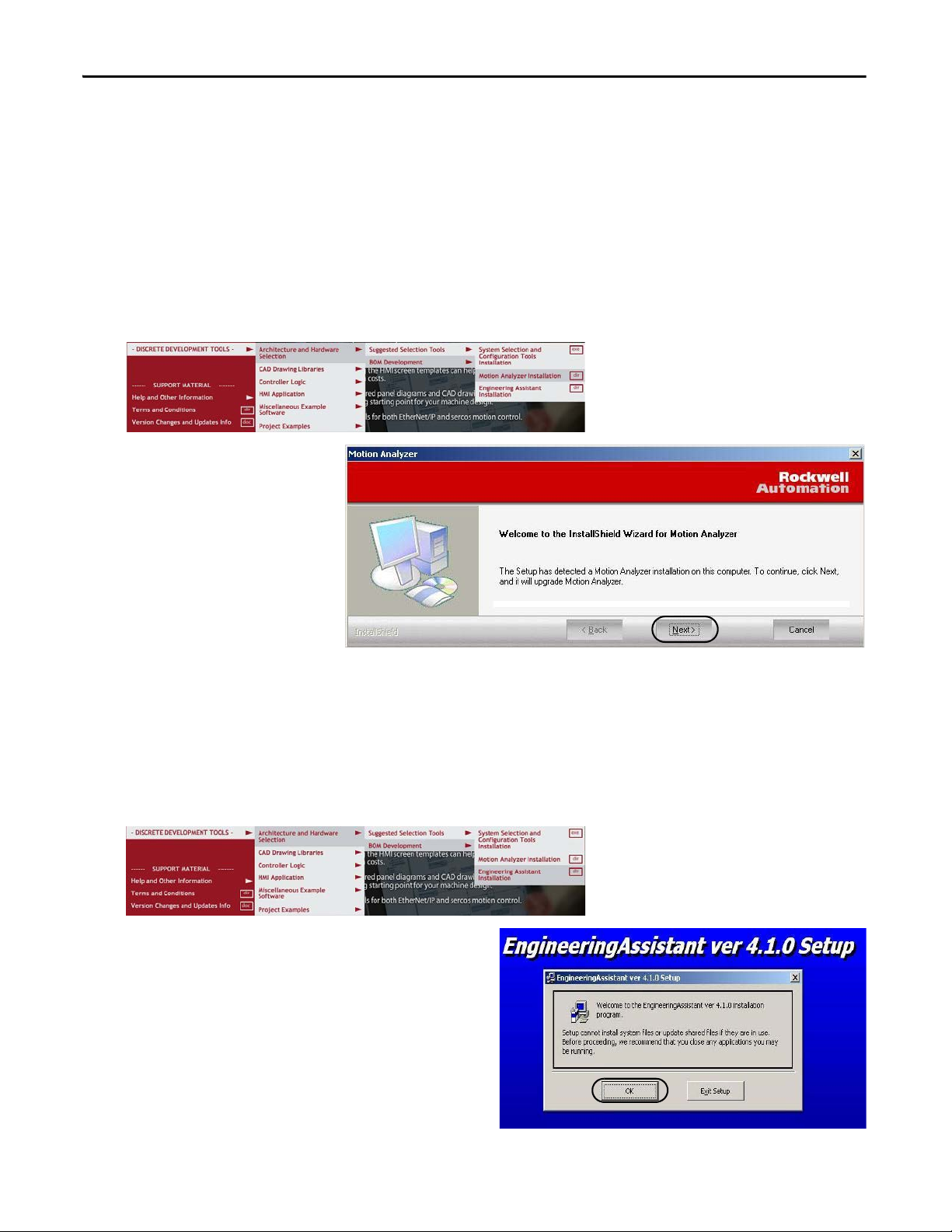
Install Motion Analyzer Software
1. Navigate to and select the Motion Analyzer Installation application on the toolkit DVD.
The Motion Analyzer
Welcome dialog box opens.
2. Click Next and follow
installation instructions.
Install Engineering Assistant Software
Follow these steps to install the Engineering Assistant Software tool from the Drives and Motion Accelerator
Toolkit DVD.
1. Navigate to and select the Engineering Assistant Installation application on the toolkit DVD.
The initial Engineering Assistant Setup dialog box
opens.
2. Click OK and follow installation instructions.
26 Rockwell Automation Publication IASIMP-QS019E-EN-P - August 2013
Page 27

Initial System Configuration Using the DMAT Wizard Chapter 1
Install Product Selection Toolbox
Follow these steps to install desired tools from the Product Selection Toolbox. ProposalWorks software
installation is the minimum requirement for completing your system bill of materials in the next chapter.
1. Navigate to and select the System Selection and Configuration Tools Installation application on the Drives
and Motion Accelerator Toolkit DVD.
The Product Selection Toolbox Software InstallShield Wizard opens.
2. Check all features that you wish to have installed.
3. Click Next and follow all install wizard instructions to complete the software installation.
ProposalWorks software installation is the minimum requirement for completing your system bill of
materials in the next chapter.
Rockwell Automation Publication IASIMP-QS019E-EN-P - August 2013 27
Page 28
Chapter 1 Initial System Configuration Using the DMAT Wizard
Run the DMAT Wizard
The DMAT Wizard creates an initial bill of materials, assembles a system drawing set, and creates a Logix
Designer project file with preconfigured controller, network, drives, and initial system program logic. All this in
just minutes by executing the following steps.
If you prefer to build these initial files using the traditional application tools, skip over this section and go directly
to Chapter 2.
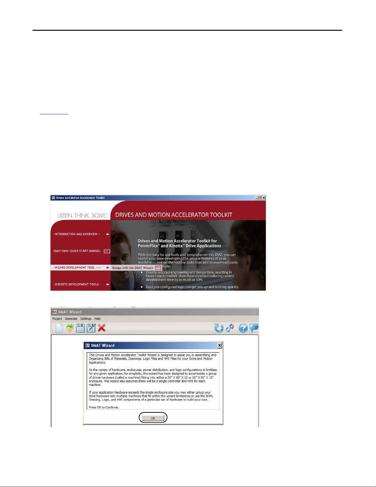
Launch the DMAT Wizard
Follow these steps to launch the DMAT Wizard and set up your wizard configuration.
1. Navigate to and select the DMAT Wizard .exe file on the Drives and Motion Accelerator Toolkit DVD
image.
The DMAT Wizard opens and a dialog box opens, explaining the general scope of the wizard.
2. Read the DMAT Wizard dialog box and click OK to continue wizard configuration.
28 Rockwell Automation Publication IASIMP-QS019E-EN-P - August 2013
Page 29

The Open or Create a Project dialog box opens.
3. Click Create New to initiate a new project.
Another configuration information dialog appears
explaining machine, application, and drive
configuration.
4. Read configuration information dialog box and
click OK to continue.
5. The New Project Wizard dialog box opens.
a. Enter Project Name.
b. Enter Project Description (optional).
c. Click Next.
6. From the Number of Machines pull-down menu, choose
the number of machines in your project.
Initial System Configuration Using the DMAT Wizard Chapter 1
A machine, as defined by the wizard, is a control system
using a single controller and housed in a single enclosure.
7. Click Next.
8. Click the Machine Name edit field and enter the desired
machine name.
For the Widg-O-matic example, the machine name
entered is WidgOmatic.
9. Click the Power Voltage Class edit field and from the
pull-down menu choose the power voltage for your
system.
For the Widg-O-matic example, the voltage level is 400/
460V AC.
10. Click the Application Qty edit field and from the pulldown menu choose the number of applications you are
configuring.
For the Widg-O-matic example, the quantity is set to 2.
11. Click Next.
The WidgoMatic machine displays with the number of
applications specified in step 10.
Rockwell Automation Publication IASIMP-QS019E-EN-P - August 2013 29
Page 30

Chapter 1 Initial System Configuration Using the DMAT Wizard
12. Click the Application_x edit fields and
rename the application names.
For the Widg-O-matic example, the two
applications were renamed Assembly and
Packaging.
13. From the Low-Voltage drives pull-down
menus, choose the number of low-voltage
drives to assign to each application.
For the Widg-O-matic example, the
quantity was set to 0 for the Assembly
application and 1 for the Packaging
application.
14. From each of the Servo Drives pull-down
menus, choose the number of servo drives
to assign to each application.
There are three types of servo drives. For
the Widg-O-matic example, the CIP
Motion Servo Drives quantity was set to 2
for the Assembly application and the
EtherNet/IP Indexing Servo Drives quantity was set to 1 for the Packaging application. Also, you can set
the number of electronic overload relays and soft-starter modules for your application.
15. Click Finish.
The DMAT Wizard dialog box opens.
16. Review the wizard information and click
OK.
The DMAT Wizard configuration dialog
box opens.
30 Rockwell Automation Publication IASIMP-QS019E-EN-P - August 2013
Page 31

Initial System Configuration Using the DMAT Wizard Chapter 1
Edit the DMAT Wizard Configuration
Follow these steps to continue editing the DMAT Wizard configuration.
1. Edit your Machine Configuration.
a. Click the machine in your project configuration tree.
In this example, the machine name is WidgOmatic. The Machine editing window appears to the right
of the project tree.
b. Click the Machine Name edit field to change the machine name.
c. Click each of the other machine configuration pull-down menus or check boxes and choose the
appropriate power and control options.
d. Select the Programming Software you intend to use for your application.
e. Repeat step 1 for each of your machines in your project.
2. Edit the Application Names.
a. Click an application in the project configuration tree.
For the WidgOmatic example, Assembly was selected. The Application editing window appears to the
right of the project configuration tree.
b. Click the Application Name edit field to change the application name.
c. Repeat step 2 for each of the applications in your project.
Rockwell Automation Publication IASIMP-QS019E-EN-P - August 2013 31
Page 32
Chapter 1 Initial System Configuration Using the DMAT Wizard
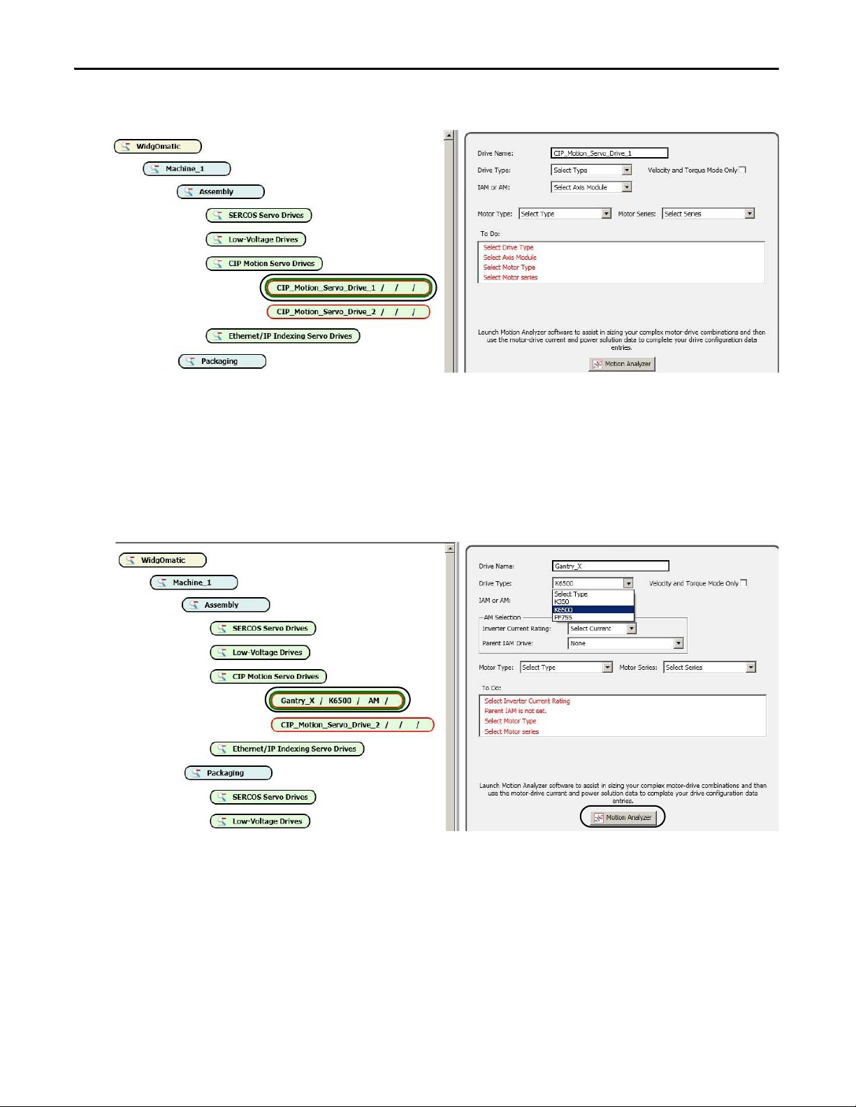
3. Edit the SERCOS, CIP Motion, and Ethernet/IP Indexing Servo Drive Configurations.
a. Select a servo drive in the project configuration tree.
For the WidgOmatic example, CIP_Motion_Servo_Drive_1 was selected. The drive editing window
appears to the right of the project configuration tree.
b. Click the Drive Name edit field and enter the desired drive name.
For the WidgOmatic example, Gantry_X was entered as the initial drive name.
c. Click the Drive Type pull-down menu to choose the drive family.
For the WidgOmatic example, the Kinetix 6500 drive was chosen.
d. For assistance in sizing complex motor/drive combinations, click Motion Analyzer or Kinetix Motion
Control Selection Guide, then return to this wizard section to complete your drive/motor
configuration.
32 Rockwell Automation Publication IASIMP-QS019E-EN-P - August 2013
Page 33

Initial System Configuration Using the DMAT Wizard Chapter 1
4. For multi-axis servo drive types, select an integrated axis module (IAM) for the first drive of its type.
For the WidgOmatic example, the Gantry_X drive is configured as an IAM module.
a. From the Spare Slot Count pull-down menu, choose the number of spare slots available on the Bulletin
2094 power rail.
b. From the Inverter Current Rating pull-down menu, choose the inverter current rating for your drive.
c. From the Converter Power Rating pull-down menu, choose the converter power rating for your drive.
d. Check Shunt Module if the Bulletin 2094 (rail-mounted) shunt module is included on your power rail.
e. Note the Slot Count value.
This is the total number of slots used on the 2094 power rail. You are prompted if the slot count exceeds
the power rail capacity.
f. Check Velocity and Torque Mode Only if you would like the servo drive axis to be configured for
Velocity mode.
To select Torque mode, use the Axis Properties configuration in the Logix Designer application. If this
box is clear, the axis configuration defaults to Position mode.
g. From the pull-down menus, choose the Motor Type and Motor Series being paired with the drive.
For the WidgOmatic example, the Gantry_X drive is configured for the Rotary Motor Type and the
MPL Motor Series.
Rockwell Automation Publication IASIMP-QS019E-EN-P - August 2013 33
Page 34
Chapter 1 Initial System Configuration Using the DMAT Wizard
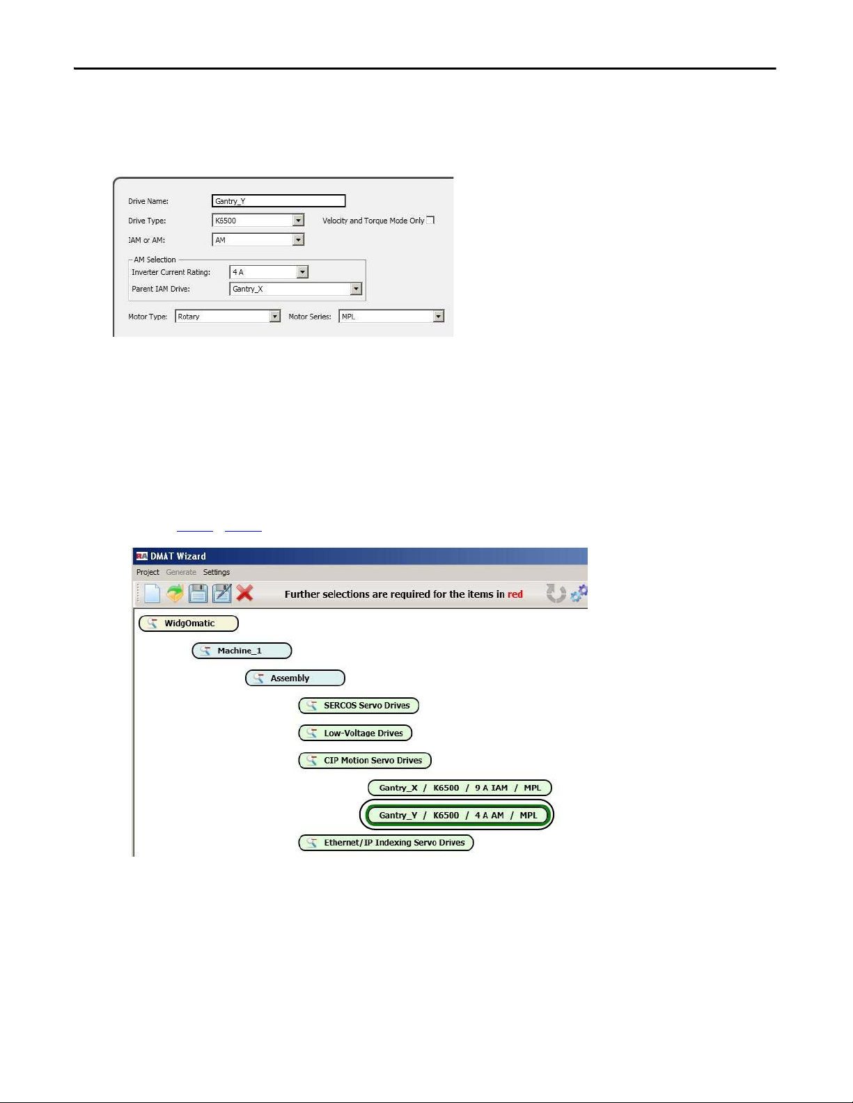
5. For single-axis drive types or secondary multi-axis servo drives, select the appropriate axis module (AM)
configuration option.
For the WidgOmatic example, the Gantry_Y drive is a Kinetix 6500 (K6500) AM module.
a. From the Inverter Current Rating pull-down menu, choose the inverter current rating for your drive.
b. From the Parent IAM Drive pull-down menu, select the parent IAM module this AM module is
assigned to (applies to multi-axis systems only).
AM modules must be assigned to a parent IAM module of the same drive family.
c. From the pull-down menus, choose the Motor Type and Motor Series being paired with the drive.
For the WidgOmatic example, the Gantry_Y drive is configured for the Rotary Motor Type and the
MPL Motor Series.
d. Repeat step 3…step 5 for all of the remaining servo drives in your project.
34 Rockwell Automation Publication IASIMP-QS019E-EN-P - August 2013
Page 35

Initial System Configuration Using the DMAT Wizard Chapter 1
6. Edit the Low-Voltage Drive configurations.
a. Select Low_Voltage_Drive_x in the project configuration tree.
For the WidgOmatic example, Low_Voltage_Drive_1 was selected. The drive editing window appears
to the right of the project configuration tree.
b. Click the Drive Name edit field and enter the desired drive name.
For the WidgOmatic example, Conveyor_Drive was entered as the initial drive name.
c. From the Drive Type pull-down menu, choose the drive family.
For the WidgOmatic example, the PowerFlex 753 (PF753) drive is selected.
d. Select the appropriate output current for the drive.
e. Repeat step 6 for all of the remaining low-voltage drives in your project.
7. Edit all electronic overload relays and soft starter modules in your application.
Current and other selection pull-down menus are similar to the drive menus.
Rockwell Automation Publication IASIMP-QS019E-EN-P - August 2013 35
Page 36

Chapter 1 Initial System Configuration Using the DMAT Wizard
8. Generate the Output Files.
Before you can generate a DMAT file, all red highlighted items must be cleared in your configuration.
a. Click Generate on the DMAT Wizard toolbar.
The Generate Outputs dialog box opens.
b. Check the Drawing Types you wish to have generated as part of the output files.
c. Click Generate.
The DMAT Wizard generates a folder containing the output files. If the Drives and Motion Accelerator
Toolkit was installed in the default directory, you will find the folder located in:
C:\Documents and Settings\My Documents\DMAT\<projectname>.
For the WidgOmatic example, the path is:
C:\Documents and Settings\My Documents\DMAT\WidgOmatic.
d. Double-click the machine folders to view the different output folders and files created.
36 Rockwell Automation Publication IASIMP-QS019E-EN-P - August 2013
Page 37

Chapter 2
Bill of Materials Completion
In this chapter you use Rockwell Automation ProposalWorks software to complete the drives and motion system
bill of materials that the DMAT Wizard created.
If you chose not to use the DMAT Wizard, follow the procedures in Appendix
ProposalWorks file before executing the following steps in this chapter. If you do not have ProposalWorks
software, you may use the Microsoft Excel file that the DMAT Wizard provides as a starting point in creating a
bill of materials with the help of your local Allen-Bradley distributor.
E to assemble the initial BOM
Before You Begin
• Complete the initial system configuration using the DMAT Wizard (refer to Chapter 1) or
• Assemble the initial BOM using ProposalWorks software (refer to Appendix E)
What You Need
• The Drives and Motion Accelerator Toolkit DVD, publication IASIMP-SP017. For a copy of the DVD,
contact your local Rockwell Automation distributor or sales representative
• ProposalWorks software, version 7.5 or later, or Microsoft Office Excel 2010
Download ProposalWorks software from http://www.rockwellautomation.com/en/e-tools/
local Allen-Bradley distributor for the Product Selection Toolbox DVD.
• The user manual for your Drives and Motion hardware. Refer to Additional Resources on page 15 for
publication numbers.
or ask your
Rockwell Automation Publication IASIMP-QS019E-EN-P - August 2013 37
Page 38

Chapter 2 Bill of Materials Completion
page 38
Import the Initial
Project BOM File
Edit Your Project BOM File
page 40
Start
Follow These Steps
Complete these steps to complete the commissioning process for your drives and motion application.
Import the Initial Project BOM File
Follow these steps to import the initial project BOM file.
1. Open ProposalWorks software, navigate to File Menu>Utilities, and select Import.
If you chose to assemble the initial BOM file using ProposalWorks software, open the ProposalWorks
(.prp) file you created in Appendix E and skip to step 2.
38 Rockwell Automation Publication IASIMP-QS019E-EN-P - August 2013
Page 39

Bill of Materials Completion Chapter 2
2. Navigate to your projects .bom file and click Open.
If the default DMAT Wizard directory was used, your project's .bom import file is in C:\Documents and
Settings\PC Name\My Documents\DMAT\ProjectName\MachineName\BOM directory.
The Widg-O-matic example file may be found in: C:\Program Files\RA_Simplification\DMAT\B-Files\
6-Project Examples\Widg-O-matic.
The ProposalWorks file opens.
3. Click Refresh to update prices in local currency.
Rockwell Automation Publication IASIMP-QS019E-EN-P - August 2013 39
Page 40

Chapter 2 Bill of Materials Completion
Edit Your Project BOM File
The DMAT Wizard you used in Chapter 1 or the steps you followed in Appendix E created an initial bill of
materials (BOM), however, individual preconfigured product listings should be reviewed and possibly edited to
fit your specific application needs.
ProposalWorks software includes a variety of specific product configuration tools to make further BOM
adjustments easy. These steps provide examples of using ProposalWorks Product Configuration Assistants to edit
your initial project BOM file to meet your specific application needs.
Follow these steps to edit the BOM file you imported or assembled for your specific application.
1. Edit a product for your specific application.
a. Double-click a product catalog number to activate the Product Configuration Assistant.
In this example, catalog number 1489-A2D250 was selected.
The Product Configuration Assistant dialog box opens. You can browse and select from a variety of
product options.
40 Rockwell Automation Publication IASIMP-QS019E-EN-P - August 2013
Page 41

b. Click the Current Rating attribute.
Bill of Materials Completion Chapter 2
In this example, the Current Rating option is 25 A. For more in-depth product selection information,
refer to product selection guides or Motion Analyzer software.
Rockwell Automation Publication IASIMP-QS019E-EN-P - August 2013 41
Page 42

Chapter 2 Bill of Materials Completion
c. For this example, select 15 A under the Current Rating field.
The catalog number field is replaced with 1489-A2D150.
d. Click Accept to make the product change within the Product Configuration Assistant.
The Product Configuration Assistant closes and your BOM file reflects the change.
42 Rockwell Automation Publication IASIMP-QS019E-EN-P - August 2013
Page 43

2. Edit a product group for your specific application.
Product group refers to an item (catalog number) that includes one or more sub items.
a. Double-click a product group catalog
number to activate the Product
Configuration Assistant.
In this example, item 13 (catalog number
2094-BMP5-M) with sub items 13.1 and
13.2 was selected.
The Product Configuration Assistant
dialog box opens. You can browse and
select from a variety of product options.
Bill of Materials Completion Chapter 2
b. Click the Inverter Current Rating attribute.
In this example, the Inverter Current Rating product option is 4 A. The sub items (13.1 and 13.2)
include the control module and connector kit accessory. For more in-depth product selection
information, refer to product selection guides or Motion Analyzer software.
Rockwell Automation Publication IASIMP-QS019E-EN-P - August 2013 43
Page 44

Chapter 2 Bill of Materials Completion
c. For this example, select 15 A under the Inverter Current Rating field.
The catalog number field was replaced with 2094-BM02-M. In addition, the 2094-EN02D-M01-S1
control module was chosen to replace the 2094-EN02D-M01-S0.
d. Click Accept to make the product change within the Product Configuration Assistant.
Sub item (13.2) also reflects the updated catalog number and description.
44 Rockwell Automation Publication IASIMP-QS019E-EN-P - August 2013
Page 45

3. Delete products not required for your specific application.
a. Select the product or product group not required for your application.
In this example, items 37 and 38 were selected.
b. From your keyboard, press delete.
The product or products are deleted from the BOM project file.
4. Save your edited BOM project file.
Bill of Materials Completion Chapter 2
5. Send the BOM project file to your Rockwell Automation distributor for a quote.
Rockwell Automation Publication IASIMP-QS019E-EN-P - August 2013 45
Page 46

Chapter 2 Bill of Materials Completion
Notes:
46 Rockwell Automation Publication IASIMP-QS019E-EN-P - August 2013
Page 47

Chapter 3
Drive Power Example
Drive I/O Example
System Layout Example
System Layout and Wiring
In this chapter you edit the set of layout and wiring drawings from the DMAT drawing library that the DMAT
Wizard created. If you chose not to use the DMAT Wizard, follow the procedures in Appendix F to assemble the
initial project drawing set before executing the steps in this chapter.
Power, I/O, and Layout Drawing Examples
AC Line Filter
LIM Module
Rockwell Automation Publication IASIMP-QS019E-EN-P - August 2013 47
Page 48

Chapter 3 System Layout and Wiring
To assist you in understanding how to best use the drawing libraries, the Widg-O-matic machine application
example is used in the drawing editing steps provided. The Widg-O-matic machine includes the following drive,
power, and control devices:
• Two Kinetix 6500 (400V-class) servo drives and motors (home and enable inputs)
• One PowerFlex 753 (400V-class) drive and induction motor
• One Kinetix 300 (400V-class) servo drive and electric cylinder
• One Bulletin 2094 line interface module (LIM)
• One ControlLogix controller and EtherNet/IP network module
Before You Begin
• Complete the initial system configuration using the DMAT Wizard (refer to Chapter 1) or
• Assemble the initial project drawing set without the DMAT Wizard (refer to Appendix F)
What You Need
• Drives and Motion Accelerator Toolkit DVD, publication IASIMP-SP017
• AutoCAD Electrical or AutoCAD software to open the DWG or DXF files
• Adobe Reader software to open PDF files
• Line Interface Module Installation Instructions, publication 2094-IN005
• System Design for Control of Electrical Noise Reference Manual, publication GMC-RM001
• System Design for Control of Electrical Noise Video, publication GMC-SP004
• The user manual for your Drives and Motion hardware. Refer to Additional Resources on page 15 for
publication numbers.
48 Rockwell Automation Publication IASIMP-QS019E-EN-P - August 2013
Page 49

System Layo ut and Wiring Chapter 3
page 50
Create a New Project
page 51
Edit Power Drawings
Edit Drive, Controller, and Safety
I/O Drawings
Edit System Communication
Drawings
Edit System Layout Drawings
page 56
page 61
page 62
Start
Follow These Steps
Complete the following steps to create your system layout and wiring drawings. These steps provide general
instructions for how to maximize the use of the toolkit’s drawing library in creating a complete drives-andmotion system layout and wiring drawing set. AutoCAD or AutoCAD Electrical software is recommended to
take full advantage of the drawing editing steps included in this chapter and the library’s device wiring references
and attributes that move with the devices as you edit your project drawing set. Some of the initial project creation
steps are illustrated using AutoCAD Electrical software, but most are generic and can be used with a variety of
software drawing packages.
If you chose not to use the DMAT Wizard, follow the instructions in Appendix F before executing the following
steps in this chapter.
Rockwell Automation Publication IASIMP-QS019E-EN-P - August 2013 49
Page 50

Chapter 3 System Layout and Wiring
Create a New Project
1. Open your drawing software.
2. Create and name your new project.
3. Add and select the toolkit library drawings assembled by the DMAT Wizard.
4. Navigate to the appropriate DWG or DXF Drawing directory that was created by the DMAT Wizard.
If the default DMAT Wizard directory was used, your project's drawing set is in C:\Documents and
Settings\PC Name\My Documents\DMAT\ProjectName\MachineName\Drawings\filetype directory.
The Widg-O-matic example drawing files may be found in: C:\Program Files\RA_Simplification\
DMAT\B-Files\6-Project Examples\Widg-O-matic\WidgOmatic_CAD\filetype directory.
If you chose to assemble the Project Drawing Set without using the DMAT Wizard, navigate to the
drawing directory you created in Appendix F.
50 Rockwell Automation Publication IASIMP-QS019E-EN-P - August 2013
Page 51

System Layo ut and Wiring Chapter 3
Edit Power Drawings
1. Open your initial drive power drawing that includes the main power distribution components.
For the Widg-O-matic machine application example, the 010_K6500_460VAC_w_LIM.dwg file is
opened. Refer to the figure on page 52.
2. Delete drives not used in your project.
For the Widg-O-matic machine application example, only two Kinetix 6500 drives are required, so the
third drive is deleted. Refer to the shaded area in the figure on page 52.
3. Open all additional drive drawings and delete drives not used in your project.
For the Widg-O-matic machine application example, both the
020_K300_460VAC_Additional_Drives.dwg file and the
020_PF750_Series_460VAC_Additional_Drives.dwg file are opened and unused drives are deleted. Refer
to the figures on page 53 and page 54.
4. Open all controller control power drawings and edit power connections and devices as necessary.
For the Widg-O-matic machine application example, no changes to the
030_CLX_GLX_120VAC_Control_Power.dwg files were required. Refer to the figure on page 55.
Rockwell Automation Publication IASIMP-QS019E-EN-P - August 2013 51
Page 52

Chapter 3 System Layout and Wiring
Select and delete
this drive.
Kinetix 6500 (460V) Drive with LIM Module
52 Rockwell Automation Publication IASIMP-QS019E-EN-P - August 2013
Page 53

Kinetix 300 (460V) Additional Drives
Select and delete
this drive.
Select and delete
this drive.
Select and delete
this drive.
System Layo ut and Wiring Chapter 3
Rockwell Automation Publication IASIMP-QS019E-EN-P - August 2013 53
Page 54

Chapter 3 System Layout and Wiring
Select and delete
this drive.
Select and delete
this drive.
Select and delete
this drive.
PowerFlex 750 (460V) Additional Drives
54 Rockwell Automation Publication IASIMP-QS019E-EN-P - August 2013
Page 55

ControlLogix/GuardLogix® (120V) Control Power with LIM Module
System Layo ut and Wiring Chapter 3
Rockwell Automation Publication IASIMP-QS019E-EN-P - August 2013 55
Page 56

Chapter 3 System Layout and Wiring
Select and delete these drive
I/O blocks.
Edit Drive, Controller, and Safety I/O Drawings
1. Open all drive, controller, and safety I/O drawings as required for your application.
For the Widg-O-matic machine application example, the 060_K6500_Digital_IO.dwg file is opened.
2. Delete devices not used in your project.
For the Widg-O-matic machine application example, only two Kinetix 6500 drives are required, so the
third and fourth I/O blocks are deleted.
Kinetix 6500 Digital I/O Example
56 Rockwell Automation Publication IASIMP-QS019E-EN-P - August 2013
Page 57

System Layo ut and Wiring Chapter 3
3. Add standard or unique I/O devices and connections required for your application.
For the Widg-O-matic machine application example, the Enable on-off switches and Home proximity
switches are added to both Kinetix 6500 drives (input 1 and 2 respectively).
Kinetix 6500 Drives (add digital I/O devices)
4. Repeat step 1…step 3 for all I/O drawings within your project.
Rockwell Automation Publication IASIMP-QS019E-EN-P - August 2013 57
Page 58

Chapter 3 System Layout and Wiring
Additional I/O library drawings, used for the Widg-O-matic machine example, are available from the Drives and
Motion Accelerator toolkit DVD. These drawings represent a sample of drive and controller I/O drawings.
Additional I/O Library Drawing Examples
I/O Library Drawings File Name Page
Kinetix 6500 Drive Safety I/O 070_K6500_Safety_IO.dwg 58
Kinetix 6500 Drive Feedback 080_K6500_Feedback.dwg 59
ControlLogix Controller Digital Inputs 090_CLX_Digital_Inputs.dwg 60
Kinetix 6500 Safety I/O
58 Rockwell Automation Publication IASIMP-QS019E-EN-P - August 2013
Page 59

Kinetix 6500 Feedback
System Layo ut and Wiring Chapter 3
Rockwell Automation Publication IASIMP-QS019E-EN-P - August 2013 59
Page 60

Chapter 3 System Layout and Wiring
ControlLogix Digital Inputs
60 Rockwell Automation Publication IASIMP-QS019E-EN-P - August 2013
Page 61

System Layo ut and Wiring Chapter 3
Select and
delete
this drive
and cable.
Edit System Communication Drawings
1. Open the communication drawing for your application.
For the Widg-O-matic machine application example, the 060_120_Ethernet_Communication.dwg file is
opened.
2. Delete network devices not used in the project.
For the Widg-O-matic machine application example, one of the Kinetix 300 drives and associated cable is
deleted.
Ethernet Communication
Rockwell Automation Publication IASIMP-QS019E-EN-P - August 2013 61
Page 62

Chapter 3 System Layout and Wiring
Copy this
Kinetix 6500
AM module.
Copy th is
Kinetix 6500
IAM module.
FP_2094-B_6500
FP_2094-B_6500
FP_2094-B_6500
FP_2094-BM_6500
FP_2094-BM_6500
FP_2094-BM_6500
3. Add any network device footprints required for your application.
a. Navigate to and open the required footprint drawings that were added to your Project Drawings folder
from the toolkit library.
b. Copy device footprints from the footprint drawings.
In this example, Kinetix 6500 IAM and AM module footprints are copied.
Kinetix 6200/6500 Footprint Drawings
c. Paste the device footprints onto your communication drawing.
d. Re-route or copy cables on the communication drawings to the added devices.
Edit System Layout Drawings
1. Open the panel layout drawing for your application.
For the Widg-O-matic machine application example, the 150_CLX_w_LIM_Sm_Panel_Layout.dwg file
is opened.
The panel layout includes a power distribution, drives, and control section. The panel is designed to
accommodate best-practice techniques used to minimize electrical noise. Refer to the System Design for
Control of Electrical Noise Reference Manual, publication GMC-RM001
.
62 Rockwell Automation Publication IASIMP-QS019E-EN-P - August 2013
Page 63

Small Panel Layout Drawing (power distribution)
DIRTY
D6
CLEAN
C2
LIM Module
AC Line Filter
CLEAN wireway for noise sensitive device
circuits.
DIRTY wireway for noise generating
device circuits.
Power Distribution
Section
System Layo ut and Wiring Chapter 3
Rockwell Automation Publication IASIMP-QS019E-EN-P - August 2013 63
Page 64

Chapter 3 System Layout and Wiring
FP_2090-UXLF-136
FP_2090-UXLF-HV330
FP_2090-XXLF-X330B
FP_2090-XXLF-375B_3d
2. Replace or add power components to your panel layout drawing.
a. Inspect power section on layout drawing for proper component footprints for the project.
b. Open the associated power footprint drawings that were added to your project drawings from the
toolkit library.
In this example, the 510_Line_Filter_Footprints.dwg file is opened.
Line Filter Footprint Drawing Examples
c. If the desired component is not represented in the current panel layout drawing, copy the proper
component footprint from the footprint drawings.
d. Delete the current component in the panel layout drawing and paste the desired component footprint
into its place.
e. Add any other required power components for your system.
64 Rockwell Automation Publication IASIMP-QS019E-EN-P - August 2013
Page 65

3. Insert drives into the Drives Placement section.
DIRTY
D6
CLEAN
C2
LIM Module
AC Line Filter
CLEAN wireway for noise sensitive device
circuits.
DIRTY wireway for noise generating
device circuits.
Drives Section
a. Open the panel layout drawing for your application.
Small Panel Layout Drawing
System Layo ut and Wiring Chapter 3
b. Open the associated drives footprint drawings that were added to your project drawings from the
toolkit library.
For the Widg-O-matic machine application example, the 430_Kinetix_6200_6500_Footprints.dwg file
is opened.
c. Copy the desired drive components from the footprint drawings for your panel layout drawing.
Rockwell Automation Publication IASIMP-QS019E-EN-P - August 2013 65
Page 66

Chapter 3 System Layout and Wiring
Copy this
Kinetix 6500
AM module.
Copy th is
Kinetix 6500
IAM module.
FP_2094-B_6500
FP_2094-B_6500
FP_2094-B_6500
FP_2094-BM_6500
FP_2094-BM_6500
FP_2094-BM_6500
DIRTY
D6
CLEAN
C2
LIM Module
AC Line Filter
CLEAN wireway for noise sensitive device
circuits.
DIRTY wireway for noise generating
device circuits.
Drives Section
Kinetix 6200/6500 Drive Footprint Drawings
d. Paste the drive footprints onto the panel layout drawing.
For the Widg-O-matic machine application example, two Kinetix 6500 servo drives, one PowerFlex 753
drive, and one Kinetix 300 drive was added to the layout drawing.
Small Panel Layout Drawing (drive placement)
66 Rockwell Automation Publication IASIMP-QS019E-EN-P - August 2013
Page 67

4. Inspect control section for required control components and proper footprints.
DIRTY
D6
CLEAN
C2
LIM Module
AC Line Filter
CLEAN wireway for noise sensitive device
circuits.
DIRTY wireway for noise generating
device circuits.
Controller and I/O
Section
a. Open the panel layout drawing for your application.
Small Panel Layout Drawing (control)
System Layo ut and Wiring Chapter 3
b. Inspect controller for required processor, I/O chassis, and I/O and communication modules, and add
footprints from the standard library as required.
c. Add any other required control components for your system.
Rockwell Automation Publication IASIMP-QS019E-EN-P - August 2013 67
Page 68

Chapter 3 System Layout and Wiring
5. Edit your Enclosure Layout Drawing.
a. Open the enclosure layout drawing for your application.
For the Widg-O-matic machine application example, the 140_SM_Enclosure_Layout.dwg file is opened.
Small Enclosure Layout Drawing
b. Inspect the drawing for operator equipment required for your system.
c. Open the associated enclosure footprint drawings that were added to your project drawings from the
toolkit library.
For the Widg-O-matic machine application example, the 600_PanelView_Plus_Footprints.dwg file is
opened.
68 Rockwell Automation Publication IASIMP-QS019E-EN-P - August 2013
Page 69

PanelView Plus Footprint Drawings
FP_2711P-B6C20A_FRONT
FP_2711P-B10C
FP_2711P-B15C
FP_2711P-T7C
FP_2711P-T10C
FP_2711P-T15C
FP_2711P-T6C
System Layo ut and Wiring Chapter 3
d. Copy the desired enclosure components from the footprint drawings for your enclosure layout drawing.
e. Paste the enclosure component footprints onto your panel layout drawing.
f. Add any other required enclosure components for your system.
Rockwell Automation Publication IASIMP-QS019E-EN-P - August 2013 69
Page 70

Chapter 3 System Layout and Wiring
Notes:
70 Rockwell Automation Publication IASIMP-QS019E-EN-P - August 2013
Page 71

Chapter 4
Machine
Module
Application
Module
Device
Module
PanelVie w Plus Terminal
Machine Faceplate
Device Faceplate
Controller Logic
HMI Application
Application
Status
Machine
Commands
Device
Commands
Device
Status
Operator
Commands
Machine Status
Logic Configuration
In this chapter you edit the preconfigured logic file that the DMAT Wizard created for your specific application.
Besides initial controller, network, and device configurations, the preconfigured logic file includes machine,
application, and device logic modules that significantly speed-up your application logic development. In
addition, the logic modules include control, status, and diagnostic code that provides information to
preconfigured operator interface faceplates that you can run on personal computers or PanelViewPlus terminals.
If you chose not to use the DMAT Wizard or desire to add or edit controller, networks, or drives since the
DMAT Wizard was executed, refer to instructions in Appendix G before executing the steps in this chapter.
Logic Modules
The machine module provides a state machine model that coordinates multiple devices and application logic for
coordinated drives and motion applications. It provides overall machine commands, for example, start, stop,
abort, clear, and reset to the application modules and the individual device modules based on the status of the
applications and devices.
Rockwell Automation Publication IASIMP-QS019E-EN-P - August 2013 71
Page 72

Chapter 4 Logic Configuration
The application modules execute the machine commands and provide the more specific application commands
to the drives and devices. It also coordinates the machine and application status, and executes the application
fault commands. In addition, the toolkit includes motion logic examples to help you create your specific
application logic.
The device modules translate the uniform machine and application commands and provide uniform status and
diagnostics from the very specific device tags and parameters. This reduces much of the non-inventive code
required to control and monitor the many unique devices.
For more information on the machine, application, and device logic modules, refer to Appendix A on page 203.
To assist you in understanding how to best use the preconfigured logic files, the Widg-O-matic machine
application is used as an example in all of the logic configuration steps.
Preconfigured Logic Modules Used in Widg-O-matic Example
Module Type File Names
Machine
Application
Device
Machine_Module
Device&Application_Status
Application_Module
Motion_Simple_Move
PF_Run_Spd
K300_EIPMove
CIPMotion_Drive_Module
PF753_Drive_Module
K300_Drive_Module
Before You Begin
Run the DMAT Wizard (refer to Chapter 1) or complete Appendix G.
What You Need
• The Drives and Motion Accelerator Toolkit DVD, publication IASIMP-SP017. For a copy of the DVD,
contact your local Rockwell Automation distributor or sales representative
• RSLogix 5000 software, version 19.0 or later, or the Logix Designer application, version 21.0 or later.
• RSLogix 5000 software, version 20.0 or later or the Logix Designer application, version 21.0 or later, to
configure Kinetix 350 servo drives, and when using ControlLogix 1756-L7xS controllers.
• The user manual for your Drives and Motion hardware. Refer to Additional Resources on page 15 for
publication numbers.
72 Rockwell Automation Publication IASIMP-QS019E-EN-P - August 2013
Page 73

Logic Configuration Chapter 4
page 77
Set String Tag Names for
Alarm History Faceplate
page 82
Create Specific Application Logic
page 88
Application Logic Creation Steps Using
Application Logic Examples
page 99
Application Logic Creation Steps Using
Tem p la te
page 79
Set Visible Rows for Equipment
Status Faceplate
Optional Step
Complete if Alarm History faceplate is used in
application.
Optional Step
Complete if Equipment Status faceplate is used
in application.
page 76
Complete Drive and Motor
Confi guration
Are you familiar with
the Logix Designer application
programming environment,
motion instructions, and
programming
PowerFlex drives?
No Yes
Start
page 74
Import the Preconfigured Logix
Designer Project
page 99
Verify and Save t he Pro ject Fi le
Follow These Steps
Complete these steps to import and configure logic modules for your drives and motion application.
Rockwell Automation Publication IASIMP-QS019E-EN-P - August 2013 73
Page 74

Chapter 4 Logic Configuration
Import the Preconfigured Logix Designer Project
Follow these steps to open the preconfigured RSLogix 5000 or Studio 5000 Logix Designer project. This
procedure is written for the Logix Designer application, but RSLogix 5000 software is similar.
1. From the Start menu, launch the Studio 5000 Logix Designer application.
The Studio 5000 dialog box opens.
2. Under the Create menu, click From Import.
3. Navigate to the Logic directory within the DMAT project.
If the Drives and Motion Accelerator Toolkit was installed in the default directory you will find the XML
file in: C:\Documents and Settings\My Documents\DMAT\ProjectName\MachineName.
74 Rockwell Automation Publication IASIMP-QS019E-EN-P - August 2013
Page 75

Logic Configuration Chapter 4
IMPORTANT
For the Widg-O-matic example, the path is:
C:\Program Files\RA_Simplification\DMAT\D-Wizard\WidgOmatic\WidgOmatic\Logic.
4. Select the logic xml file and Click Open.
5. From the Revision pull-down menu, choose the version of RSLogix 5000 software, versions 18, 19, or 20,
or the Logix Designer application, version 21 or later, to import into.
RSLogix 5000 software must be version 19.0 or later. RSLogix 5000 software, version 20.0 or later, is required to configure
Kinetix 350 servo drives and when using ControlLogix 1756-L7xS controllers.
6. Click Import to save and open the project as an ACD file.
After the import process is complete, the project opens and the
controller organizer displays all of the preconfigured project
components including the controller, network, device configurations,
the preconfigured logic program files, and the faceplate and control
AOI files.
From this point on, you complete the logic module configuration for
your specific drives and motion application guided by the remaining
sections of this chapter.
To gain a complete understanding of the preconfigured project
organization and logic refer to Appendix A on page 203.
Rockwell Automation Publication IASIMP-QS019E-EN-P - August 2013 75
Page 76

Chapter 4 Logic Configuration
Complete Drive and Motor Configuration
The DMAT Wizard uses default values for module properties (creating your axes) and axis properties
(configuring your axes). When your application requires modifications to these fields, refer to the appropriate
steps in Appendix G.
Changing Default Properties in Appendix G
Procedure Go To Do This
Complete CIP motion drive module configuration step 19 on page 298 Calculate and enter a value for the Bus Capacitance field.
Complete CIP motion axis properties step 8 on page 302 Review the Scaling, Load, and Actions categories. Make changes, if necessary.
Complete sercos drive module configuration step 13
Complete sercos drive axis properties step 8 on page 308 Review the Motor Feedback, Units, Conversion, and Fault Actions tabs. Make changes, if necessary.
Setting Drive Motor Ratings
You must manually change the motor series and motor type for each axis imported into your Logix Designer
project file. The DMAT Wizard Logix Designer import file sets all drive motor type selections to Rotary, MPL,
and to the largest available power rating as default. This is true even if you change the motor series and type in the
DMAT Wizard. Those selections are reflected in the BOM only.
on page 306 Calculate and enter a value for the Additional Bus Capacitance field.
Follow these steps to edit the Drive/Motor tab.
1. Under My_MotionGroup in the Controller Organizer,
double-click the Servo_Drive_x_Axis.
In the WidgOmatic example, Gantry_X_Axis was selected.
2. In the Axis Properties window, select
Motor in the Categories tree.
3. Click Change Catalog.
The Change Catalog Number dialog
box opens.
4. Scroll though the available catalog numbers and select the desired
motor catalog number for your actual hardware configuration.
5. Click OK.
6. Repeat for each axis configured in My_MotionGroup.
76 Rockwell Automation Publication IASIMP-QS019E-EN-P - August 2013
Page 77

Logic Configuration Chapter 4
Set String Tag Names for Alarm History Faceplate
If you plan to use the Alarm History faceplate with your HMI application, follow these steps to set the
application and device string tag names to match your application and device module names. These string names
are used within the alarm messages indicating the device or application origin of the alarm.
1. Expand the Controller folder in your Controller Organizer and double-click Controller Tags.
The controller tags open in the workspace.
2. Expand one of your application status tags (UDT_AppStatus) and/or module status tags
(UDT_ModuleStatus) and select the value field of the string tag named XXX.Name.
For the Widg-O-matic application example, the Assembly tag (UDT_AppStatus data type) is expanded
and the Assembly.Name string tag value field is selected.
3. Click .
The String Browser dialog box opens.
4. Type the name of the associated application
or device module.
This string name is used within the alarm
history messages providing the fault origin.
5. Click OK.
The string tag value field updates with the name you typed in. For the Widg-O-matic application example,
the value is Assembly.
6. Repeat step 1…step 5 for each application status (UDT_AppStatus) tag and device status
(UDT_ModuleStatus) tag within the Controller Tags of your project.
Rockwell Automation Publication IASIMP-QS019E-EN-P - August 2013 77
Page 78

Chapter 4 Logic Configuration
For the Widg-O-matic application example, these application and device string tag names were entered.
Packaging
Conveyor_Drive
Diverter_Drive
Gantry_X_Drive
Gantry_Y_Drive
78 Rockwell Automation Publication IASIMP-QS019E-EN-P - August 2013
Page 79

Logic Configuration Chapter 4
Set Visible Rows for Equipment Status Faceplate
If you plan to use the Equipment Status faceplate with your HMI application, follow these steps to set the
Inp_NumRowsVis tag value within the faceplate AOI of the device you intend to place in the first row.
1. Determine how many of the nine available rows you will use in the Equipment Status faceplate.
Refer to Chapter 5 beginning on page 101 for an overview of the faceplate so you can determine how many
status rows you require and what device you would like to place in the first row.
For the Widg-O-matic application example, all four devices are included in the Equipment Status
faceplate, with the Gantry X Axis placed in the first row.
• Gantry X Axis
• Gantry Y Axis
• Conveyor
• Diverter
2. Open the R02_Monitor routine for the device located in the first row of the Equipment Status faceplate
and navigate to the device specific faceplate AOI.
For the Widg-O-matic application example, the R04_Monitor routine in the P04_Gantry_X_Drive
program was opened.
3. Click (View Configuration Dialog ) to open the AOI properties.
4. Navigate to the Inp_NumRowsVis tag and
select the Value.
5. Enter the number of devices you
determined in step 1
For the Widg-O-matic application
example, 4 was entered.
6. Click OK to close AOI properties and
complete the update.
.
Rockwell Automation Publication IASIMP-QS019E-EN-P - August 2013 79
Page 80
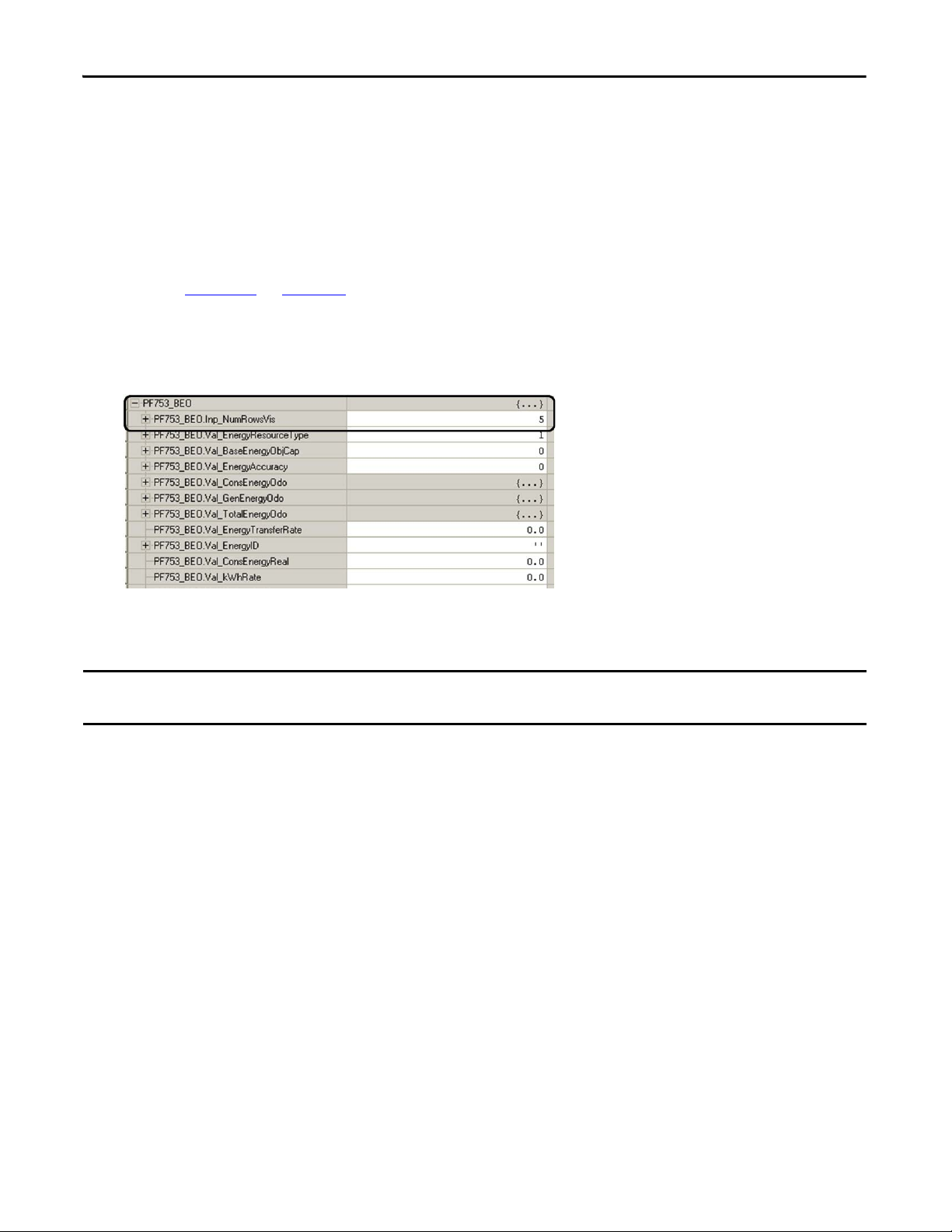
Chapter 4 Logic Configuration
IMPORTANT
Set Visible Rows for Equipment Status Faceplate for Energy Monitoring
If you plan to use the Equipment Status faceplate with Energy Monitoring in your HMI application, follow these
steps to set the Inp_NumRowsVis tag value within the energy object AOI of the device you intend to place in the
first row.
1. Determine how many of the nine available rows you will use in the Equipment Status faceplate for Energy.
Refer to Chapter 5 on page 145 for an overview of the faceplate so you can determine how many status
rows you require and what device you would like to place in the first row.
2. Open the controller tags and expand the energy object tag for the device located in the first row of the
Equipment Status faceplate for Energy (DriveName_BEO).
3. Enter the number of required rows as the tag value for the Inp_NumRowsVis attribute.
In this example, the number of required rows is 5.
You must use the device module routines with energy support if you plan to use the equipment status faceplate for energy
monitoring.
80 Rockwell Automation Publication IASIMP-QS019E-EN-P - August 2013
Page 81
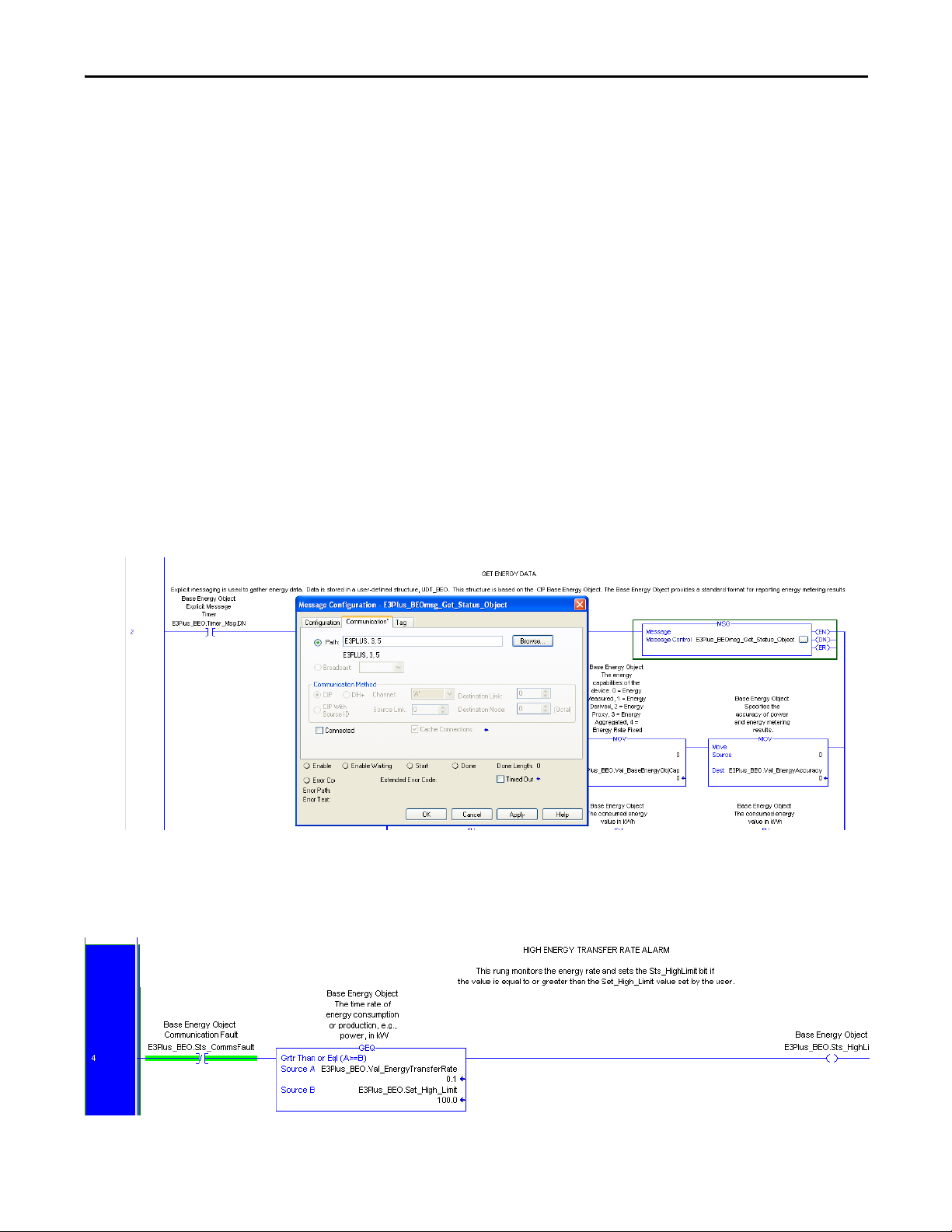
Logic Configuration Chapter 4
Set MSG Path in the E3 Plus Energy Monitoring Routine
If the device modules with energy monitoring are used, an additional routine is included in the device program
named R05_Energy. This routine gathers the energy data and energy related status and stores the data in the base
energy object tag (UDT_BEO).
Rung 2 of the energy routine includes at least one explicit message for getting energy attributes from the device
(some devices require more than one explicit message). The path for each MSG instruction is configured on
import of the device module. However, for E3 Plus device modules, the path must be configured to include the
port number of the 193-DNENCAT device (3) and the node address of the E3 Plus overload relay.
Follow these steps to configure the path for your E3 Plus device:
1. Click the ellipse button on the MSG instruction in rung 2 to launch the Message Configuration dialog
box.
2. Click the Communication tab.
3. Add the 193-DNENCAT port number and your E3 Plus node address to your path configuration in the
following format: _DeviceName, 3, #.
4. Click OK.
Rung 4 of the energy routine monitors the energy rate and sets a status bit if the value exceeds the high alarm
limit. The high-alarm limit default setting is 100. Configure this value to set the kW high-alarm limit for your
device.
Rockwell Automation Publication IASIMP-QS019E-EN-P - August 2013 81
Page 82

Chapter 4 Logic Configuration
IMPORTANT
Create Specific Application Logic
Now that you have imported and configured all of the machine, application, and device modules, you can begin
creating the specific application logic for your machine. You create your application logic within the
R10_ApplicationCode routine of the application module. There are two methods for creating specific
application logic for your machine.
The first method involves selecting and importing preprogrammed logic examples into the Application Code
routine. These logic examples help familiarize less experienced users with the basics behind motion instructions
and/or controlling PowerFlex drives via their add-on profiles. These preprogrammed logic examples are designed
to work seamlessly with the application module and can help further reduce programming time.
The second method provides a blank template with placeholders if you choose to write your application-specific
logic from scratch. This method is recommended for users who feel comfortable with the Studio 5000 Logix
Designer programming environment and who also have experience with motion instructions and/or controlling
PowerFlex drives via their add-on profiles.
Application Code Logic Template Overview
To assist you in creating specific-application logic that interfaces with the preconfigured machine, application,
and device modules, a logic template is included in the R10_ApplicationCode routine of the application module.
It includes placeholders for both run and stop sequences. All of the application logic examples also follow this
same template.
Program the stop sequence to make sure all active devices are properly stopped.
82 Rockwell Automation Publication IASIMP-QS019E-EN-P - August 2013
Page 83

Logic Configuration Chapter 4
============================================
BY DEFAULT THE FOLLOWING RUNGS WILL BE ERRORED AND THEREFORE MUST BE ADDRESSED...
MODIFY OR OVERWRITE THESE RUNGS WITH THE APPLICATION SPECIFIC LOGIC
***PLEASE NOTE THE STOP SEQUNCE IS LOCATED DIRECTLY BELOW THE RUN SEQUENCE***
============================================
0 NOP
BY DEFAULT THE FOLLOWING RUNGS WILL BE ERRORED AND THEREFORE MUST BE ADDRESSED...
MODIFY OR OVERWRITE THESE RUNGS WITH THE APPLICATION SPECIFIC LOGIC
***PLEASE NOTE THE STOP SEQUNCE IS LOCATED DIRECTLY BELOW THE RUN SEQUENCE***
============================================
============================================
RUN SEQUNCE
============================================
1 NOP
SEQUENCE INITIATE
This rung is a placeholder where Application specific logic can be inserted.
By default, RunSEQ[0] is initially set to 1 following a Machine START command (i.e. "MachineName".Cmd.START).
Refer to the Machine Commands rungs located in the R03_Control routine of the Application Module.
2
e
e
e
e
e
e
e
e
e
e
e
e
e
e
e
e
e
Equal
Source A RunSEQ[0]
0
Source B 1
EQ
U
Move
Source 10
Dest RunSEQ[0]
0
MO
V
SEQUENCE PLACEHOLDER
This rung is a placeholder where Application specific logic can be inserted.
3
e
e
e
e
e
e
e
e
e
e
e
e
e
e
Equal
Source A RunSEQ[0]
0
Source B 10
EQ
U
Move
Source 20
Dest RunSEQ[0]
0
MO
V
SEQUENCE PLACEHOLDER
This rung is a placeholder where Application specific logic can be inserted.
4
e
e
e
e
e
e
e
e
e
e
e
e
e
e
Equal
Source A RunSEQ[0]
0
Source B 20
EQ
U
Move
Source 30
Dest RunSEQ[0]
0
MO
V
This rung can easily be duplicated if addtional sequence steps are needed.
This rung can easily be duplicated if addtional sequence steps are needed.
Logic Placeholder
Run Sequence Template
Rockwell Automation Publication IASIMP-QS019E-EN-P - August 2013 83
Page 84

Chapter 4 Logic Configuration
The run sequence is initiated by a machine START command via the start logic in the R03_Control routine of
the application module. By default, the run sequence is initiated by placing a value of 1 in the RunSEQ[0] tag.
When the RunSEQ[0] tag is set to 1, the first step in the run sequence is executed, starting the run sequence.
Each of the rungs in the run sequence provides a placeholder where you can insert application-specific step logic.
The Run-sequence logic may include, for example, motion instructions, drive commands, and/or other
conditional diagnostic logic.
The move (MOV) instruction is a placeholder to advance the run sequence to the next step by incrementing the
RunSEQ[0] tag. Each step in the run sequence requires a unique value assigned in ascending order. The steps
typically increase by multiples of five or ten. By default, the run-sequence template steps 1…10…20…30, and so
on. Before moving to the next step, a predetermined condition must normally be met to make sure the current
step is complete.
First Run Sequential Step Example
This Widg-O-matic application code first-run step (RunSEQ[0] = 1) example includes a motion axis move
(MAM) instruction, an instruction error detection check, and an process complete (PC) check. Before the
MOV instruction indexes to the next sequence step (for example, value 5 into RunSEQ[0] tag), the PC check
must be met indicating that the move is complete. The instruction error detection check is used to detect a
module fault in the application, preventing the run sequence from inadvertently hanging on a step.
84 Rockwell Automation Publication IASIMP-QS019E-EN-P - August 2013
Page 85

Final Run Sequential Step Example
Logic Configuration Chapter 4
Much like the first run-step example rung, this Widg-O-matic final run step example also includes a motion axis
move (MAM) instruction, an instruction error detection check, and an process complete (PC) check. The only
difference is that the PC bit is used to reset the RunSEQ[0] tag back to a value of 1, which will repeat the motion
sequential steps for continuous operation. If continuous operation is not required, the final step could just simply
end the Run Sequence or just remain at this step indefinitely.
Rockwell Automation Publication IASIMP-QS019E-EN-P - August 2013 85
Page 86

Chapter 4 Logic Configuration
============================================
STOP SEQUENCE
============================================
5 NOP
============================================
STOP SEQUENCE
============================================
SEQUENCE INITIATE
This rung is a placeholder where Application specific logic can be inserted.
By default, StopSEQ[0] is initially set to 1 following a Machine STOP command (i.e. "MachineName".Cmd.STOP).
Refer to the Machine Commands rungs located in the R03_Control routine of the Application Module.
6
e
e
e
e
e
e
e
e
e
e
e
e
e
e
e
e
e
Equal
Source A StopSEQ[0]
0
Source B 1
EQ
U
Move
Source 10
Dest StopSEQ[0]
0
MO
V
SEQUENCE INITIATE
This rung is a placeholder where Application specific logic can be inserted.
By default, StopSEQ[0] is initially set to 1 following a Machine STOP command (i.e. "MachineName".Cmd.STOP).
Refer to the Machine Commands rungs located in the R03_Control routine of the Application Module.
SEQUENCE PLACEHOLDER
This rung is a placeholder where Application specific logic can be inserted.
This rung can easily be dulpicated if addtional sequence steps are needed.
7
e
e
e
e
e
e
e
e
e
e
e
e
e
e
Equal
Source A StopSEQ[0]
0
Source B 10
EQ
U
Move
Source 20
Dest StopSEQ[0]
0
MO
V
SEQUENCE PLACEHOLDER
This rung is a placeholder where Application specific logic can be inserted.
This rung can easily be dulpicated if addtional sequence steps are needed.
SEQUENCE COMPLETE
By default, the Application is STOPPED when StopSEQ[0] reaches 999.
Refer to the Application Status rungs located in the R02_Monitor routine of the Application module to modify the
conditions that detemine when the Application is STOPPED (i.e. "ApplicationName".Stopped).
8 Equal
Source A StopSEQ[0]
0
Source B 20
EQ
U
Move
Source 999
Dest StopSEQ[0]
0
MO
V
SEQUENCE COMPLETE
By default, the Application is STOPPED when StopSEQ[0] reaches 999.
Refer to the Application Status rungs located in the R02_Monitor routine of the Application module to modify the
conditions that detemine when the Application is STOPPED (i.e. "ApplicationName".Stopped).
(End
)
Logic Placeholder
Stop Sequence Template
The stop sequence is initiated by a machine STOP command via the stop logic in the R03_Control routine of
the application module. By default, the stop sequence is initiated by placing a value of 1 in the StopSEQ[0] tag.
When the StopSEQ[0] tag is set to 1, the first step in the stop sequence is executed, starting the stop sequence.
Each of the rungs in stop sequence provides a placeholder where application specific step logic can be inserted.
The stop sequence logic may include, for example, motion instructions, drive commands and/or other
conditional diagnostic logic.
86 Rockwell Automation Publication IASIMP-QS019E-EN-P - August 2013
Page 87

Logic Configuration Chapter 4
The move (MOV) instruction is a placeholder to advance the stop sequence to the next step by incrementing the
StopSEQ[0] tag. Each step in the stop sequence requires a unique value be assigned in ascending order. The steps
typically increase by multiples of five or ten. By default, the stop sequence-template steps 1…10…20…30 …999.
Before moving to the next step, a predetermined condition must normally be met to make sure the current step is
complete.
By default, the stop sequence ends when the StopSEQ[0] tag value reaches 999. The StopSEQ[0] tag is then
monitored in the R02_Monitor routine of the application module for a value of 999 and then sets the
ApplicationName.Stopped tag. The machine module monitors the ApplicationName.Stopped tag to determine
when the application was properly stopped.
First Stop Sequential Step Example
This Widg-O-matic first-stop step example includes two motion axis stop (MAS) instructions, an instruction
error detection check, and axis stopped check. Before the MOV instructions indexes to the next sequence step
(for example, value 10 into the StopSEQ[0] tag), both axes must be stopped. An error detection check is used to
detect a module fault in the application module, preventing the stop sequence from inadvertently hanging on a
step.
Rockwell Automation Publication IASIMP-QS019E-EN-P - August 2013 87
Page 88

Chapter 4 Logic Configuration
Final Stop Sequential Step and Sequence Complete Example
This Widg-O-matic final-stop step and complete logic example includes logic to disable the two axes and
confirm that the axes are disabled before confirming the application is stopped. Identical to the stop-sequence
template, the stop-sequence complete rung sets the StopSEQ[0] tag value to 999 which indicates the stop
sequence is complete.
Application Logic Creation Steps Using Application Logic Examples
If you are unfamiliar with Rockwell Automation’s general Logix5000 commands, Logix5000 motion commands,
PowerFlex parameters, and/or are seeking common application methods for creating specific application logic,
use these steps to create your specific application logic.
Toolkit Application Logic Example Overview
The toolkit provides a variety of common application logic examples designed to help you create your specific
application logic. The logic examples are organized by the device modules they support.
• K300 Logic Examples – Supporting Kinetix 300 Ethernet drives
• Motion Logic Examples – Supporting CIP Motion, sercos, and virtual motion drives
• PF Logic Examples – Supporting all PowerFlex drives
• Widg-O-matic Example – Supporting a combination of two Kinetix 6500 CIP Motion drives, one
PowerFlex 753 drive, and one Kinetix 300 Ethernet drive.
88 Rockwell Automation Publication IASIMP-QS019E-EN-P - August 2013
Page 89

Logic Configuration Chapter 4
Kinetix 300 Logic Examples
Application Example File Name Description
EIP Position K300_EIPMove_App Enter position, speed, and accel/decel rates to perform incremental position moves.
EIP Velocity K300_EIPVel_App Run Kinetix 300 drive at a speed reference.
Index K300_Index_App Configure and run Kinetix 300 drive in indexing mode.
Motion Logic Examples
Application Example File Name Description
2-Axis Gear Motion_Gear_App Gear two axes together.
Adv/Retard Phasing Motion_Jog_PhaseMove_App Perform advance/retard phase moves with a MAM instruction on top of MAJ instruction.
2-Axis PCAM Motion_PCAM_App Jog an axis and Position Cam another axis to it.
Simple Move Motion_Simple_Move_App Move single axis with MAM instruction by using incremental moves.
Safe Limited Speed Motion_SLS_App For single axis, monitor SLS request in module. Reduce speed when SLS request detected.
TCAM Motion_TCAM_App Time Cam an axis.
PowerFlex Logic Examples
Application Example File Name Description
Run Forward / Reverse PF_Fwd_Rev_App Run PowerFlex drive forward, stop, and then run reverse.
Run at Speed PF_Run_Spd_App Run PowerFlex drive at a speed reference.
PF525 Run Forward / Reverse PF525Only_Fwd_Rev_App.L5X Run PowerFlex drive forward, stop, and then run reverse.
PF525 Run at Speed PF525Only_Run_Spd_App.L5X Run PowerFlex drive at a speed reference.
Widg-O-matic Logic Examples
Application Example File Name Description Applic ation Created From
Widg-O-Matic Assembly WOm_Assy_App1 Execute 2-axis simple moves for gantry. Motion_Simple_Move_App
Widg-O-Matic Packaging WOm_Pack_App2
Intermittently run PowerFlex drive for conveyor and
execute Kinetix 300 position commands for diverter.
PF_Run_Spd_App
K300_EIPMove_App
Rockwell Automation Publication IASIMP-QS019E-EN-P - August 2013 89
Page 90

Chapter 4 Logic Configuration
755
00300
Conveyor
Y-Se rvo
X-Ser vo
X-Y Gantry
Kinetix 6500
Drives
Diverter
Kinetix 300
Drive
PowerFlex 753
Drive
S
e
rv
o
M
o
t
o
r
D
r
i
v
e
n
E
l
e
c
t
r
i
c
C
y
l
i
nd
e
r
I
n
d
u
c
t
i
o
n
M
o
t
o
r
Assembly
Packaging
Widg-O-matic Logic Example Overview
To assist you in understanding how to best use the logic examples, the Widg-O-matic machine application is
used as an example.
We recommend you study the Widg-O-matic assembly and packaging applications to see the interaction of the
machine, application, and device modules within the application logic. The Widg-O-matic examples are created
by using basic drives and motion application examples included in the toolkit. After you’ve studied these
examples, create your own applications using the basic drives and motion examples.
The Widg-O-matic application example is an excellent canvas to experiment with the other application
examples. The Widg-O-matic example includes two servo axes, one PowerFlex drive, and one Kinetix 300 drive.
So, it is possible for you to import and study all of the application examples.
Widg-O-matic Machine Application Example
90 Rockwell Automation Publication IASIMP-QS019E-EN-P - August 2013
Page 91

Logic Configuration Chapter 4
The Widg-O-matic machine example has two applications (assembly and packaging) and has the following run
sequences.
Assembly Application
Step Simple X-Y Gantry Run Sequence Value
1 Lower Y-axis, incremental distance 2.0 revs
2 Dwell, time 1.0 s
3 Raise Y-axis, incremental distance 2.0 revs
4 Extend X-axis, incremental distance 3.0 revs
5 Lower Y-axis, incremental distance 2.0 revs
6 Dwell, time 1.0 s
7 Raise Y-axis, incremental distance 2.0 revs
8 Retract X-axis, incremental distance 3.0 revs
9 Repeat and run continuously until the stop sequence is initiated by a machine abort or stop command.
Packaging Application
Step Conveyor and Diverter Run Sequence Drive
1 Verify diverter is in EIP Incremental Position mode Kinetix 300
2 Set conveyor drive direction forward and speed reference at 50 Hz PowerFlex 753
3 Enable diverter Kinetix 300
4 Configure diverter position, speed, accel/decel and start an incremental move Kinetix 300
5 Start conveyor, run at speed 3.0 seconds PowerFlex 753
6 Stop conveyor PowerFlex 753
7 Configure diverter position, speed, accel/decel and start an incremental move Kinetix 300
8 Start conveyor, run at speed 4.0 seconds PowerFlex 753
9 Stop conveyor PowerFlex 753
10 Repeat and run continuously until the stop sequence is initiated by a machine abort or stop command.
Rockwell Automation Publication IASIMP-QS019E-EN-P - August 2013 91
Page 92

Chapter 4 Logic Configuration
Import Application Logic Examples
Follow these steps to add logic examples to your R10_ApplicationCode routine within your application
modules.
1. Expand the Tasks folder in the Controller Organizer.
2. Navigate to and open the R10_ApplicationCode routine within your first application program file.
For the Widg-O-matic application example, the R10_ApplicationCode routine within the P02_Assembly
program was opened.
3. Select all rungs of the R10_ ApplicationCode routine.
4. Right-click the selected rungs and choose Import Rungs.
92 Rockwell Automation Publication IASIMP-QS019E-EN-P - August 2013
Page 93
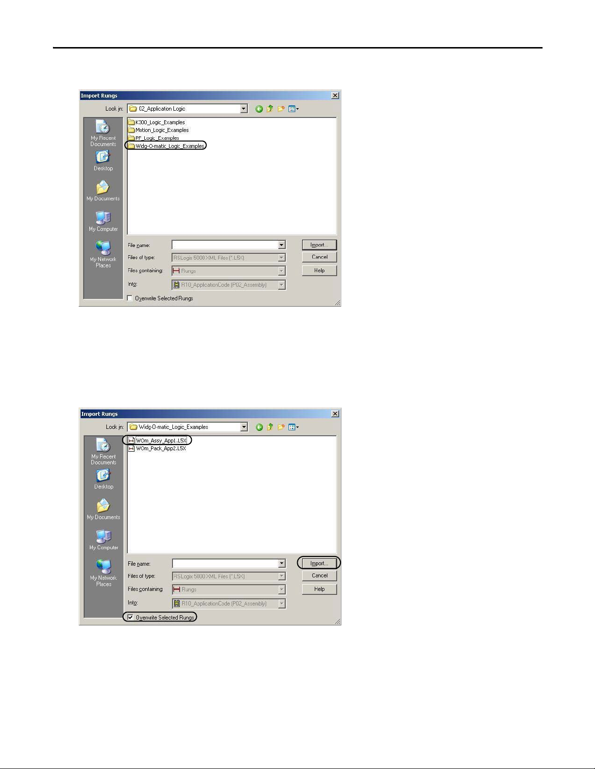
5. Navigate to the 02_Application Logic folder within the toolkit’s files folder.
Logic Configuration Chapter 4
Your personal computer’s harddrive path is
C:\Program Files\RA_Simplification\DMAT\B-Files\02_Application Logic.
6. Double-click the logic examples folder of choice.
For the Widg-O-matic application example, the Widg-O-matic_Logic_Examples folder was opened.
7. Select the desired logic example file to start your application logic.
For the Widg-O-matic application example, the WOm_Assy_App1.L5X file is selected.
8. Check Overwrite Selected Rungs.
9. Click Import.
Rockwell Automation Publication IASIMP-QS019E-EN-P - August 2013 93
Page 94

Chapter 4 Logic Configuration
The Import Configuration dialog box opens.
10. Click Tags within the Import Content organizer.
The Configure Tag References dialog box opens.
11. Replace tag names in the Final Name column with the associated axis or drive names for your application.
For the Widg-O-matic application example, _X_AxisName was replaced with Gantry_X_Axis and
_Y_AxisName was replaced with Gantry_Y_Axis.
12. Click OK to complete rung import.
13. Repeat step 2…step 12 for each logic example you wish to import.
94 Rockwell Automation Publication IASIMP-QS019E-EN-P - August 2013
Page 95

Logic Configuration Chapter 4
============================================================================================
============================================
SERCOS / CIP MOTION
SIMPLE INCREMENTAL MOVE
The following application example demonstrates how to control a SERCOS / CIP MOTION drive using sequencers &
Motion Instructions.
While the Machine is STARTING / RUNNING, the drive will be operated as follows:
1) Lower Y-Axis - Incremental Distance -2.0 revs
2) DWELL - Time 1 sec
3) Raise Y-Axis - Incremental Distance 2.0 revs
4) Extend X-Axis - Incremental Distance 3.0 revs
5) Lower Y-Axis - Incremental Distance -2.0 revs
5) DWELL - Time 1 sec
6) Raise Y-Axis - Incremental Distance 2.0 revs
7) Retract X-Axis- Incremental Distance -3.0 revs
8) Repeat
The Run Sequence is continuously repeated until the Stop Sequence is initiated by a Machine ABORT or STOP
command.
============================================================================================
0 NOP
============================================================================================
============================================
SERCOS / CIP MOTION
SIMPLE INCREMENTAL MOVE
The following application example demonstrates how to control a SERCOS / CIP MOTION drive using sequencers &
Motion Instructions.
While the Machine is STARTING / RUNNING, the drive will be operated as follows:
1) Lower Y-Axis - Incremental Distance -2.0 revs
2) DWELL - Time 1 sec
3) Raise Y-Axis - Incremental Distance 2.0 revs
4) Extend X-Axis - Incremental Distance 3.0 revs
5) Lower Y-Axis - Incremental Distance -2.0 revs
5) DWELL - Time 1 sec
6) Raise Y-Axis - Incremental Distance 2.0 revs
7) Retract X-Axis- Incremental Distance -3.0 revs
8) Repeat
The Run Sequence is continuously repeated until the Stop Sequence is initiated by a Machine ABORT or STOP
command.
============================================================================================
============================================================================================
============================================
RUN SEQUENCE
============================================================================================
============================================
1 NOP
============================================================================================
============================================
RUN SEQUENCE
============================================================================================
============================================
INCREMENTAL MOVE
Lower Y-Axis
Incremental Distance -2.0 revs
2 Equal
Source A RunSEQ[0]
0
Source B 1
EQ
U
EN
DN
E
R
IP
PC
Motion Axis Move
Gantry_Y_Axis ...
Motion Control Gantry_Y_Axis_Ctrl.MI.MAM[1]
Move Type 1
Position -2
Speed Gantry_Y_Axis_Ctrl.Data.MoveSpd[1]
1.0
Speed Units Units per sec
Gantry_Y_Axis_Ctrl.Data.MoveAccel[0]
50.0
% of Maximum
Decel Rate Gantry_Y_Axis_Ctrl.Data.MoveDecel[0]
50.0
Decel Units % of Maximum
MAM
Motion Axis Move
INCREMENTAL MOVE
Lower Y-Axis
Incremental Distance -2.0 revs
For the Widg-O-matic Assembly application example, the following rungs are imported. The rungs include a
series of five incremental moves.
Sercos/CIP Motion Simple Incremental Move
14. Repeat step 1…step 12 for every application program you have in your drives and motion system.
Axis
Rockwell Automation Publication IASIMP-QS019E-EN-P - August 2013 95
Accel Rate
Accel Units
Page 96

Chapter 4 Logic Configuration
For the Widg-O-matic application example, the R10_ApplicationCode routine within the P03_Packaging
program was also opened and the WOm_Pack_App2.L5X file was imported.
96 Rockwell Automation Publication IASIMP-QS019E-EN-P - August 2013
Page 97

Logic Configuration Chapter 4
IMPORTANT
For the Widg-O-matic WOm_Pack_App2.L5X file import, the PowerFlex 753 faceplate
_Conveyor_DriveName is replaced with Conveyor_Drive and the Kinetix 300 input, output, and control
tag _Diverter_DriveName are replaced with Diverter_Drive.
For application examples with Kinetix 300 devices, it is required that you also configure the component reference tag name
for the Kinetix 300 drive.
Rockwell Automation Publication IASIMP-QS019E-EN-P - August 2013 97
Page 98

Chapter 4 Logic Configuration
============================================
K300/POWERFLEX
K300- EIP POSITION MODE
POWERFLEX-RUN FORWARD
Widg-O-Matic Packaging Example
The following application example demonstrates how to control a K300 and a PowerFlex drive using sequencers.
Note that the K300 MUST be in EIP Incremental Position mode ( EIP mode = 1, Reference Source = 2)
For this example, the mode is set in the K300 Module Reset Sequence. Tag K300_Ctrl.Cmd.DriveMode is set to 2.
The Run sequence will Configure and run incremental position moves using K300 EIP Move AOI and Set a speed
reference
and Start/Stop a PowerFlex Drive.
While the Machine is STARTING / RUNNING, the drives will be operated as follows:
1) Verify K300 is in EIP Incremental Position mode.
1) Set Direction FWD, Speed Reference 50 Hz
2) Enable K300 drive.
3) Configure Position, Speed, Accel/Decel and start an Incremental Move.
2) Start drive, run at speed 3 sec
3) Stop drive
4) Configure Position, Speed, Accel/Decel and start an Incremental Move.
2) Start drive, run at speed 4 sec
3) Stop drive
6) Repeat
The Run Sequence is continuously repeated until the Stop Sequence is initiated by a Machine ABORT or STOP
command.
============================================================================================
============================================
0 NOP
============================================
K300/POWERFLEX
K300- EIP POSITION MODE
POWERFLEX-RUN FORWARD
Widg-O-Matic Packaging Example
The following application example demonstrates how to control a K300 and a PowerFlex drive using sequencers.
Note that the K300 MUST be in EIP Incremental Position mode ( EIP mode = 1, Reference Source = 2)
For this example, the mode is set in the K300 Module Reset Sequence. Tag K300_Ctrl.Cmd.DriveMode is set to 2.
The Run sequence will Configure and run incremental position moves using K300 EIP Move AOI and Set a speed
reference
and Start/Stop a PowerFlex Drive.
While the Machine is STARTING / RUNNING, the drives will be operated as follows:
1) Verify K300 is in EIP Incremental Position mode.
1) Set Direction FWD, Speed Reference 50 Hz
2) Enable K300 drive.
3) Configure Position, Speed, Accel/Decel and start an Incremental Move.
2) Start drive, run at speed 3 sec
3) Stop drive
4) Configure Position, Speed, Accel/Decel and start an Incremental Move.
2) Start drive, run at speed 4 sec
3) Stop drive
6) Repeat
The Run Sequence is continuously repeated until the Stop Sequence is initiated by a Machine ABORT or STOP
command.
============================================================================================
============================================
============================================================================================
============================================
RUN SEQUENCE
============================================================================================
============================================
1 NOP
============================================================================================
============================================
RUN SEQUENCE
============================================================================================
============================================
SET K300 MODE
Set drive mode specific for this application.
This tag is used in Reset Routine in K300 Drive module to set Mode.
2 Move
Source 2
Dest Diverter_Drive_Ctrl.Data.AppMode
2
MOV
K300 Drive Mode for
applicatio
n
SET K300 MODE
Set drive mode specific for this application.
This tag is used in Reset Routine in K300 Drive module to set Mode.
For the Widg-O-matic packaging example, the following rungs are imported. The rungs include a series of
incremental moves for the Kinetix 300 Diverter_Drive and Start/Stop and Speed reference commands for the
PowerFlex Conveyor_Drive.
Kinetix 300 and PowerFlex Drives Incremental Move
98 Rockwell Automation Publication IASIMP-QS019E-EN-P - August 2013
Page 99

Logic Configuration Chapter 4
IMPORTANT
Application Logic Creation Steps Using Template
If you are familiar with Rockwell Automation’s general Logix5000 commands, Logix5000 motion commands,
PowerFlex parameters, and have a good idea of your specific run/stop sequences, use these steps to guide you
through your specific application logic creation.
1. Formulate and list your run sequence steps.
2. Add your initial run sequence step (RunSEQ[0] = 1) to the R10_ApplicationCode routine of your
imported application module.
3. Add remaining run sequence steps (RunSEQ[0] > 1) and interlocks to remaining R10_ApplicationCode
routine rungs and adding run sequence rungs as required.
4. Formulate and list your stop sequence steps.
5. Add your initial stop sequence step (StopSEQ[0] = 1) to the R10_ApplicationCode routine of your
imported application module.
6. Add remaining stop sequence steps (1 < StopSEQ[0] < 999) and interlocks to remaining
R10_ApplicationCode routine rungs and adding stop sequence rungs as required.
7. Add your final stop sequence step (StopSEQ[0] = 999) to the R10_ApplicationCode routine of your
imported application module.
8. Determine any special reset logic requirements for your application and edit the R04_Reset Routine in the
application module. Refer to Appendix B on page 219 for more information on logic module
customization.
For other common application code requirements, not included in preprogrammed application modules
or logic examples, refer to Appendix B on page 219.
Verify and Save the Project File
1. Click on the Logix Designer application toolbar to verify your controller.
This software function verifies your controller programs and displays errors/warnings, if any.
2. Make corrections to programs as needed.
If a PowerFlex 70 drive is used as part of the Low Voltage Drive configuration, you need to manually set the data type for
each PowerFlex 70 drive AOI.
3. Click to save your Logix Designer project file.
Rockwell Automation Publication IASIMP-QS019E-EN-P - August 2013 99
Page 100

Chapter 4 Logic Configuration
Notes:
100 Rockwell Automation Publication IASIMP-QS019E-EN-P - August 2013
 Loading...