

Page 1
General Handling Procedures
for Medium Voltage Controllers
BULLETIN 1500 / 1900
QUICK START
A T T E N T I O NA T T E N T I O N
Read this document before you attempt to move your controller.
The instructions are intended to help you safely inspect and
transport your Rockwell Automation Medium Voltage product
to its installation site. Failure to follow the procedures within
this document may result in personal injury and/or damage to
your controller.
Page 2
IMPORTANT: General Handling Procedures
A T T E N T I O NA T T E N T I O N
Keep the controller in an upright position. Some units are
top-heavy and may fall over if they are tilted too far.
Ensure all controller doors are closed and retaining bolts are
tight before moving the controller.
Keep the controller bolted to the shipping skid to minimize
the possibility of it tipping. Do not remove the skid until the
controller is at the installation area.
For handling of NEMA 3R enclosures, refer to your
instruction manual or contact Rockwell Automation.
Never attempt to lift or move the controller by
any means other than the handling methods
listed in this publication. Failure to do so may
result in personal injury or damage to the
controller.
Page 3

Table of Contents
Scope ......................................................................................................... 1
Receiving .................................................................................................. 1
Accessories ................................................................................................ 1
Storage ...................................................................................................... 1
Using a Fork Lift ....................................................................................... 2
Overhead Lifting ....................................................................................... 2
Laying Controllers Down .......................................................................... 4
Rod or Pipe Rollers ................................................................................... 4
Opening the Controller Doors ................................................................... 5
Leveling the Controller ............................................................................. 6
MV-QS050B-EN-P – November 2006
Page 4

Page 5

General Handling Procedures for Medium Voltage Controllers
1
Scope This document pertains to the Bulletin 1500 and 1900 family of
medium voltage (MV) controllers. Additional procedures may apply
for specific equipment. Please refer to other documentation provided
with the equipment.
Receiving
Upon receiving the controller, remove the packing and check for
damage that may have occurred during shipping. Report any damage
immediately to the claims office of the carrier. The customer must
make all claims for damage to the carrier as soon as possible after
receipt of the equipment. Rockwell Automation will be glad to offer
reasonable assistance to the customer in resolving such damage claims.
Accessories Accessory items may be shipped with the controller. During the post-
delivery inspection, all accessories or loose items listed on the shipping
documentation should be located before moving the controller to an
installation or storage area. Be careful not to mix the accessory kits.
Tags may indicate the location of accessories.
Note: Bus splice links are shipped with the equipment in a separate
box. Retain these links for future use as the equipment is
assembled.
Storage Important: Store the controller in the following conditions if it will
not be installed immediately after receiving it.
Store the controller in a clean, dry, dust-free environment.
Storage temperature should be maintained between –20°C to
65°C (-4°F to 149°F). Relative humidity must not exceed 95%,
non-condensing. The controller should be stored in a climatecontrolled building with regulated air circulation to avoid damage.
Important: Remove all packaging from the controller while storing it
to prevent condensation from damaging the cabinet and/or components.
Factory installed space heaters are recommended to prevent
condensation if storage temperature fluctuates or if humidity
exceeds 85%.
Medium voltage controllers that are designed for indoor use are
not shipped with sufficient packaging for outdoor storage. Make
sure you have provided adequate protection for your controller if
you plan to store it outside. Temporary electrical heating to prevent
condensation should also be installed. A space heater rated at
approximately 150 watts per vertical section is adequate for most
controllers. To avoid fire hazard, remove any loose packing or
flammable material from the cabinet prior to starting the space
heaters.
MV-QS050B-EN-P – November 2006
Page 6

2 General Handling Procedures for Medium Voltage Controllers
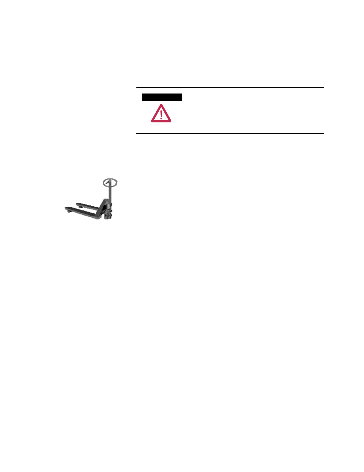
Using a Fork Lift A fork lift is the most common and versatile method for moving a
single controller.
1. Insert forks into openings located at the front of the skid.
2. Carefully balance the controller on the forks. Depending upon the
options installed, the center of gravity may be offset.
3. Use safety strap(s) to ensure the controller remains steady.
Overhead Lifting
1. Attach rigging to the lifting apparatus.
When two or more controllers are shipped as an assembly, overhead
lifting is the recommended method for safely moving it in your facility.
A T T E N T I O NA T T E N T I O N
2. Do not pass slings or cables through the support holes in the
lifting angle brackets. Use slings with safety hooks or shackles.
3. Select or adjust the rigging lengths to compensate for the unequal
length and weight distribution of the load. Maintain the controller
in an upright position.
4. To reduce the tension of the rigging and the compressive load on
the lifting device, do not allow the angle between the lifting cables
to exceed 45 degrees from the vertical plane. (See Figure 1)
Ensure that the load ratings of the lifting device,
slings, hooks and shackles have a lifting capacity
rated equal to or greater than the load. Failure to
do so may result in personal injury and/or
equipment damage. For your controller’s
specific weight, refer to shipping weights on the
packing slip.
MV-QS050B-EN-P – November 2006
Page 7

General Handling Procedures for Medium Voltage Controllers
Figure 1 – Overhead Lifting with a Rigging Apparatus
5. Use a spreader bar to lift the controller if there is insufficient
overhead space to permit a 45-degree angle of the lifting cables
with respect to the vertical. Ensure the load rating of the spreader
bar is sufficient to handle the controller. (See Figure 2)
3
Figure 2 – Overhead Lifting with a Spreader Bar
6. Lift the controller only a few inches at first and verify that it is
properly secured and balanced before proceeding further.
A T T E N T I O NA T T E N T I O N
Some controllers may contain heavy equipment
that could be adversely affected by lifting.
Ensure your controller does not have loose items
inside when lifting. Failure to do so could result
in personal injury and/or equipment damage.
MV-QS050B-EN-P – November 2006
Page 8

4 General Handling Procedures for Medium Voltage Controllers
Laying Controllers Down It may be necessary to lay the controller down while you are moving
or installing it. Contact Rockwell Automation for special considerations
with your controller. Be sure to provide a description of your controller
including the series number, which can be found on a metal nameplate
midway up the cabinet on the right-hand flange.
Rod or Pipe Rollers
1. Place 2-inch. x 6-inch boards or equivalent under the skid. Make
2. Carefully move the shipping skid over the roller pipes until the
3. The controller may now be rolled to its designated location.
This method offers an alternative to using a fork lift or an overhead
lifter, and should only be attempted on a level surface.
sure the boards are at least 30 cm (one foot) longer than the
shipping skid.
pipes bear the entire weight of the controller.
Steady the load to prevent tipping and use pinch bars to aid the
movement.
2 in. X 6 in. Min.
Figure 3 – Pipe Rolling the Controller
MV-QS050B-EN-P – November 2006
Page 9

General Handling Procedures for Medium Voltage Controllers
The doors to your controller are designed to prevent access to any
Opening the Controller
Doors
medium voltage compartment while the unit is energized.
5
Note: The door opening procedure for ArcShield™ arc resistant
units differs from the standard listed below.
Standard (Non-ArcShield) Units
1. Move the isolating switch handle to the OFF position; this is the
lower position of the handle (see Figure 4). You must move the
isolating switch handle to the OFF position before any door
providing access to a medium voltage compartment will open.
2. Loosen the door retaining screws of the main power cell door,
which is adjacent to the isolating switch handle, and open the
door.
For cabinets with two power cells, each medium voltage section
contains its own separate door interlock. Once you have moved one
of the isolating switch handles to the OFF position, you can open the
corresponding medium voltage door without disengaging the second
isolating switch handle.
Figure 4 – Isolation Switch Handle in the OFF Position
MV-QS050B-EN-P – November 2006
Page 10

6 General Handling Procedures for Medium Voltage Controllers
Opening the Controller
ArcShield Units
Doors (cont.)
Refer to label on unit door (see Figure 5 for typical label).
Figure 5 – Typical Label on Arc Resistant Door
Refer to the controller’s User Manual for specific information
regarding the interlocking configuration.
MV-QS050B-EN-P – November 2006
Page 11

General Handling Procedures for Medium Voltage Controllers
7
Levelling the Controller Note: The mounting surface for the equipment is to be flat within
±1 mm per meter. Installation of metal shim s is an acceptable
method of compensating for mounting surfaces that are out of
tolerance. Mounting surfaces that are not flat may inhibit
proper set-up and operation of latches and interlocks of the
equipment.
1. Do not remove the controller from the shipping skid until it is at
the installation area.
2. The controller is bolted to the shipping skids at the front and back
of the cabinet. At the rear, lag bolts hold angle brackets to the
mounting channel at the base of the cabinet. The front lag bolts
are located just inside the lower cabinet door at the corners of the
cabinet bottom. Remove the lag bolts and the angle brackets,
then remove the controller from the shipping skid.
3. It is important to position the controller on a level surface at the
final destination, especially if it will be joined to another one. A
flush mating surface between the controllers is required to ensure
a proper attachment. A level concrete surface should be prepared
for the controller; however, shimming the controller is suitable,
provided the shimming object is dense enough to bear the weight
of the controller for an extended period of time. Sheet metal
shims are suggested (wooden shims are not recommended).
A T T E N T I O NA T T E N T I O N
Refer to the technical drawings and installation
manual for your controller’s mounting instructions.
Failure to correctly anchor the cabinet may resu lt
in damage to the equipment or injury to personnel.
Contact the area Rockwell Automation sales
office if you do not have these documents.
MV-QS050B-EN-P – November 2006
Page 12

Medium Voltage Products, 135 Dundas Street, Cambridge, ON, N1R 5X1 Canada, Tel: (1) 519.740.4100, Fax: (1) 519.623.8930, www.ab.com/mvb
Publication MV-QS050B-EN-P – November 2006
Supersedes Publication MVB-5.0 – March 199 9 Copyright © 2006 Rockwell Automation, Inc. All rights reserved. Printed in Ca nada.
 Loading...