

Page 1
Installation Instructions
(Catalog Number 1897-NOV)
Contents
Use this document as a guide when installing the 1897-NOV output
module.
To See page
Prevent Electrostatic Discharge Below
Understand Compliance to European Union Directives 2
Calculate Power Requirements 2
Determine Module Placement 3
Install the Module and Remote Termination Panel 3
Key the Backplane Connector 4
Connect the Wiring to the Module 4
Connect Wiring to the Remote Termination Panel 5
Connect Cables to the Remote Termination Panel 5
Grounding Your Field Devices 7
Configuring Your Output Module 7
Reading Data from Your Output Module 9
For this reference information See page
Troubleshooting with the Indicators 10
UL/CSA Hazardous Location Approval 11
Specifications 12
Prevent Electrostatic Discharge
The analog output module is sensitive to electrostatic discharge.
ATTENTION: Electrostatic discharge can damage
integrated circuits or semiconductors if you touch
!
backplane connector pins. Follow these guidelines
when you handle the module:
• Touch a grounded object to discharge static potential
• Wear an approved wrist-strap grounding device
• Do not touch the backplane connector or
connector pins
• Do not touch circuit components inside the module
• If available, use a static-safe work station
• When not in use, keep the module in its
static-shield box
Publication CIG-5.1 – April 1998
Page 2

Fast Isolated Analog Output Module2
Understand Compliance to European Union Directives
If this product has the CE mark it is approved for installation within
the European Union and EEA regions. It has been designed and
tested to meet the following directives.
EMC Directive
This product is tested to meet Council Directive 89/336/EEC
Electromagnetic Compatibility (EMC) and the following standards,
in whole or in part, documented in a technical construction file:
• EN 50081-2EMC – Generic Emission Standard,
Part 2 – Industrial Environment
• EN 50082-2EMC – Generic Immunity Standard,
Part 2 – Industrial Environment
This product is intended for use in an industrial environment.
Low Voltage Directive
This product is tested to meet Council Directive 73/23/EEC
Low Voltage, by applying the safety requirements of EN 61131–2
Programmable Controllers, Part 2 – Equipment Requirements and
Tests.
Calculate Power Requirements
For specific information required by EN 61131-2, see the appropriate
sections in this publication, as well as these Allen-Bradley
publications:
Publication Publication number
Industrial Automation Wiring and Grounding Guidelines
For Noise Immunity
Guidelines for Handling Lithium Batteries AG-5.4
Automation Systems Catalog B111
1770-4.1
This equipment is classified as open equipment and must be mounted
in an enclosure during operation to provide safety protection.
The module receives its power through the 1771 I/O power supply
and requires 2A from the backplane.
Add this current to the requirements of all other modules in the I/O
chassis to prevent overloading the chassis backplane and/or
backplane power supply.
Publication
CIG-5.1 – April 1998
Page 3
Fast Isolated Analog Output Module 3
Determine Module Placement in the I/O Chassis
Install the Module and the Remote Termination Panel
Place your module in any I/O module slot of the I/O chassis except
for the extreme left slot. This slot is reserved for PC processors or
adapter modules.
ATTENTION: Do not insert or remove modules from
the I/O chassis while system power is ON. Failure to
!
Group your modules to minimize adverse affects from radiated
electrical noise and heat. We recommend the following.
observe this rule could result in damage to module
circuitry.
• Group analog input and low voltage dc modules away from ac
modules or high voltage dc modules to minimize electrical noise
interference.
• Do not place this module in the same I/O group with a discrete
high-density I/O module when using 2-slot addressing.
ATTENTION: Remove power from the 1771 I/O
chassis backplane and field wiring arm before
!
removing or installing an I/O module.
• Failure to remove power from the backplane or
wiring arm could cause module damage, degradation
of performance, or injury.
• Failure to remove power from the backplane could
cause injury or equipment damage due to possible
unexpected operation.
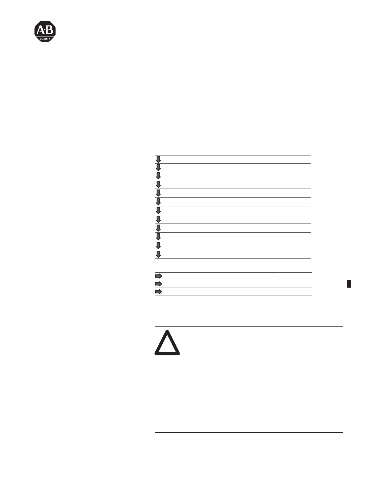
Place the module in the card guides on the top and bottom of the chassis that guide the module into position.
1
1
Important: Apply firm even pressure on the module to seat it into its
backplane connector.
1771-A1B, -A2B, -A3B1, -A4B Series B I/O chassis1771-A1B, -A2B, -A3B, -A3B1, -A4B I/O chassis
Snap the chassis latch over the
top of the module to secure it.
Swing the chassis locking bar
down into place to secure the
modules. Make sure the locking
pins engage.
Publication
CIG-5.1 – April 1998
Page 4
Fast Isolated Analog Output Module4
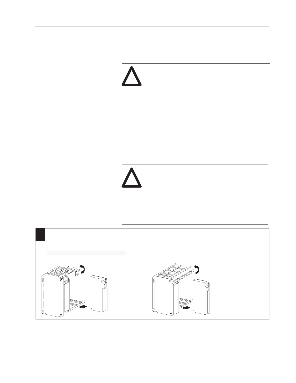
2
Key the Backplane Connector
Place your module in any slot in the chassis
except the leftmost slot which is reserved for
processors or adapters.
Position the keying bands in the backplane connectors
to correspond to the key slots on the module.
Place the keying bands:
between 26 and 28
between 32 and 34
You can change the position of these bands if
subsequent system design and rewiring makes
insertion of a different type of module necessary.
I/O chassis
Upper Connector
11022-I
3
Module End of
1771-NC cable
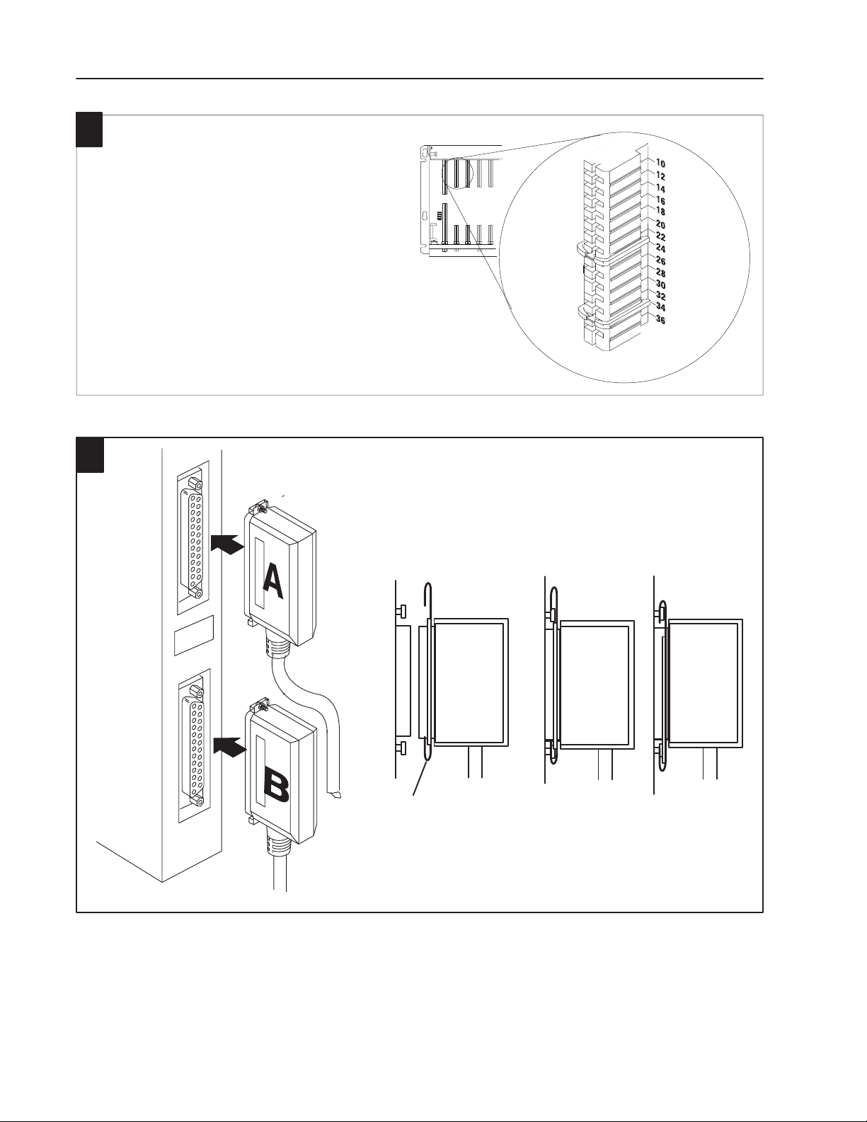
Connect the Cable to the Module
1. Slide the locking bar up.
2. Insert the cable connector into the mating connector on the
front of the module.
3. Slide the locking bar down over the mating pins on the
module to lock the connector onto the module.
Cable Connector
Module
Connector
Locking bar
11023-I
Publication
CIG-5.1 – April 1998
Page 5

Connect Wiring to the Remote
5
4
Termination Panel
The 1897-NOV module is cable-connected to a 1771-RTP4
remote termination panel using cat. no. 1771-NC6 (6 ft) or
-NC15 (15 ft) cables. This RTP has straight-through wiring. The
remote termination panel mounts on standard DIN 1 or DIN 3
mounting rails.
Each channel has four connections: R, I, O, and S.
Field wiring to the RTP is the same for all RTP variations.
Channel 1 uses R1, I1, O1, and S1; channel 2 uses R2, I2,
O2, and S2; and so on for the remaining channels.
1. Strip 3/8 inch (9.25 mm) of insulation from
the 22-12 AWG wire.
2. Insert the wire into the open connector slot.
3. Tighten the screw to clamp the wire.
Fast Isolated Analog Output Module 5
Remote
Termination
Panel (RTP)
I = input
R = return
Output
Type
Voltage
Connect To
+ O1 Output
-
R1 Return
Shield S1 Shield
Connect the Cables to the
Remote Termination Panel
1. Insert the RTP end of the cable into the connector
on the the RTP.
2. Alternately tighten the retaining screws into
the connector on the RTP until secure.
Screw
Example:
channel 2
Channel 1 Connections
R1 = Return 1
I1 = Input 1
O1 = Output 1
S1 = Shield 1
RTP End of
1771-NC cable
channel 1
Note: Terminals W1, W2
and W3 are spares.
Do not use terminals CR
and CL.
Field Wiring
O = output
S = shield
RTP4
19621
DIN R
Publication
11024-I
CIG-5.1 – April 1998
Page 6

Fast Isolated Analog Output Module6
1
Remote Te
rmination Panel Dimensions
RTP4
3.0
(75.0)
AB
Dimensions
back of
DIN rail
2.3
(58.4)
Inches
(Millimeters)
J8
J7
J6
J5
5.30
(134.6)
J1
J2
J3
J4
2.3
(58.4)
Building Your Own Cables
You can terminate the analog module to a terminal block by cutting
the 25-pin RTP end connector off the standard cable and wiring to
your terminal block. Refer to the following table for wire termination
designations.
Wire Termination Designations
Module Top Connector Module Bottom Connector
Channel Number Signal 37-Pin Connector Wire Color Channel Number Signal 37-Pin Connector Wire Color
I1 20 Blk I5 20 Blk
Publication
1
2
3
4
CIG-5.1 – April 1998
O1
22 Blk/Wht
5
O5 22 Blk/Wht
R1 21 Wht/Blk R5 21 Wht/Blk
I2 24 Orn I6 24 Orn
O2
26 Orn/Blk
6
O6 26 Orn/Blk
R2 25 Wht R6 25 Wht
I3 29 Grn I7 29 Grn
O3
31 Grn/Blk
7
O7 31 Grn/Blk
R3 30 Grn/Wht R7 30 Grn/Wht
I4 33 Blu I8 33 Blu
O4
35 Blu/Blk
8
O8 35 Blu/Blk
R4 34 Blu/Wht R8 34 Blu/Wht
Not used
36 Red
37 Red/Wht
Page 7

Fast Isolated Analog Output Module 7
Grounding Your Field Devices
When using shielded cable, ground the foil shield and drain wire
only at one end of the cable. We recommend that you wrap the foil
shield and drain wire together and connect them to the “S”
connection on the RTP for the particular channel. All shield
connections are internally connected together in the RTP so that only
one wire is required to ground the entire remote termination panel.
Connect a wire from the “SH” connection on the RTP to a ground
stud on the metal cabinet in which the remote termination panel is
mounted.
If you do not want to ground a particular shield at the RTP, you can
remove the jumper for that particular channel. This will allow the
shield to float at the RTP end. To remove a jumper, you must cut it
out. Once the jumper is removed it cannot be replaced. Clip as
close to the circuit board as possible at both ends to completely
remove it. The jumpers are labeled J1 through J8, corresponding to
channels 1 through 8 respectively.
Communicating with Your Output Module
Jumpers for
channels
5 through 8
Refer to publication 1770-4.1, Programmable Controller Wiring and
Grounding Guidelines, for additional information.
The 1897–NOV module uses digital data transfers for backplane data
transfer. Configure your module as a double density module (1 slot
addressing). Address all channels individually.
The module uses channel 8 as a trigger to synchronize data transfer
to the module’s digital-to-analog converters (DACs). All DACs are
updated following a write of data to channel 8. This update occurs
regardless of whether data changed on any other channel.
When any channel other than channel 8 is written to, the data is
parsed and stored internally, but the DAC is not updated until a
channel 8 write is completed. The status of which channel(s) change
(and, as a result, modify the analog outputs on the module on the
next trigger event) is reflected in the digital input image table. The
least significant byte of the digital input word will indicate the
updated channel(s). If the input bit is 1 (high), on the next trigger
event, the analog output value associated with that channel changes.
J8
J7
J6
J5
J1
J2
J3
J4
Jumpers for
channels
1 through 4
Publication
CIG-5.1 – April 1998
Page 8

Fast Isolated Analog Output Module8
C
C
Á
Á
Á
Á
Output Image Definition
The digital output data resides in the modules Rack/Group/Slot
location in the programmable controller output image table. The
format of the 16-bit data word written to the module over the
backplane is:
Dec. Bits 15 14 13 12 11 10 09 08 07 06 05 04 03 02 01 00
Octal Bits 17 16 15 14 13 12 11 10 07 06 05 04 03 02 01 00
Ch
Sign
ID
2ChID 1ChID 0
The data word is a 12 bit analog value: –4095 through 4095 –
corresponding to –10.7V through 10.7V. Bits 12,13,14 represent the
number of the channel which is to receive this data:
Data MSB Data word Data LSB
Program
To set a single channel ’immediately’ on the NOV.
Action
N7:0 –> Channel number to be updated: 0 through 7.
N7:1 –> Analog value to be set –4095 through 4095.
Decimal Bit 14 Bit 13 Bit 12
Octal
ÁÁÁÁ
Bit 16
0
0
0
0
1
1
1
1
Bit 15
0
0
1
1
0
0
1
ÁÁ
1
Bit 14
0
1
0
1
0
1
0
ÁÁ
1
hannel
hannel
Number
1
2
3
4
5
6
7
ÁÁÁ
8
The bit pattern is MASKED onto the data in the ladder program.
The following ladder rung is an example of how to accomplish this
masking:
MOV
MOVE
SOURCE
DESTINATION
CONTROL:
N7:1
1000
O:002
29672
N12:50
NOTE 1: Analog value must be set first, then
masked by the channel data.
NOTE 2: The channel and analog data must be
present (in the same scan, prior to this
rung) when this rung is executed in order
for the correct channel to get the data.
Publication
CIG-5.1 – April 1998
BTD
BIT
FIELD DISTRIB
SOURCE
SOURCE BIT
DESTINATION
DESTINATION BIT
LENGTH 3
N7:0
O:002
29672
7
0
12
002
IOT
Page 9

Fast Isolated Analog Output Module 9
Reading Data from Your Module
Dec. Bits 15 14 13 12 11 10 09 08 07 06 05 04 03 02 01 00
Octal Bits 17 16 15 14 13 12 11 10 07 06 05 04 03 02 01 00
Word
The digital status data resides in the modules Rack/Group/Slot
location in the programmable controller input image table. The
following table shows the format of the 16 bit data word read from
the module over the backplane:
Input Data Definition
1
Not used
Word Bit Description
Bits
00–07
Bit 08 DAC update in progress – set when the module is busy updating
Bit 09 Module in Reset – set when the I/O Reset line is asserted indicating
Bits
10–15
Module
Reset
Channel “Armed” – set when the channel has an output which is
going to change the next time that trigger event occurs. Bit 00
corresponds to channel 1, bit 01 corresponds to channel 2, and so
on.
the DAC’s
that all channels have been zeroed (including all pending changes)
Not used
DAC
update in
progress
Channel
“Armed”
Interpreting the Indicator Lights
NOTE: If a channel output value is changed, that value (which is
different from the current state of the output) is written to the
“pending output” buffer. The corresponding “channel armed” bit
will then be set. If you change that channel value back to the current
output value without a trigger event, the “channel armed” bit will
still be set.
The front panel of the analog module contains two bi-color
indicators: a red/green RUN/FLT (fault) indicator and a red/green
CAL/COM indicator. The CAL/COM indicator is not used on this
module.
Run/Fault indicator. This indicator will flash green until the
diagnostic test is completed at power up.. If a fault is found
RUN/FLT
CAL/COM
initially or occurs later, the RUN/FLT indicator turns red.
Not used
10528-I
Publication
CIG-5.1 – April 1998
Page 10

Fast Isolated Analog Output Module10
Both indicators are
At power-up, an initial module self-check occurs. The module
checks:
• correct RAM operation
• EPROM operation
• EEPROM operation
The RUN/FAULT indicator will be green when the check is
completed satisfactorily. It will flash green until the first valid block
transfer write has been received. If a fault is found initially or occurs
later, the RUN/FLT indicator turns red.
After passing initial diagnostics, the module turns the RUN/FLT
indicator to flashing green. The indicator will turn red if a fault is
detected.
Troubleshooting with the
Indicators
Indication Probable Cause Recommended Action
OFF
RUN/FLT indicator ON red
RUN/FLT indicator is
flashing green
RUN/FLT indicator is green but
module data is wrong (for
example, with cable off, input
channel data values are at
minimum scale values)
The following table shows indications, probable causes and
recommended actions to correct common faults which may occur.
No power to module
Possible short on the module
LED driver failure
Microprocessor, oscillator or EPROM failure Replace module.
If immediately after power–up, indicates RAM or
EPROM failure.
If during operation, indicates possible
microprocessor or backplane interface failure.
Power–up diagnostics successfully completed. Normal operation.
Internal fuse may be bad Replace module
Check power to I/O chassis.
Recycle as necessary.
Replace module.
Replace module.
Replace module.
Publication
CIG-5.1 – April 1998
Page 11

Fast Isolated Analog Output Module 11
A certification product label
étiquette de certification d’un produit par la CSA
rature code ratin
aux du code de températur
CSA Hazardous Location Approval Approbation d’utilisation dans des emplacements dangereux par
la CSA
CSA certifies products for general use as well as for use in hazardous locations.
Actual CSA certification is indicated by the product label
not by statements in any user documentation.
as shown below
Example of the CS
T
o comply with CSA certification for use in hazardous locations, the following
information becomes a part of the product literature for CSA-certified Allen-Bradley
industrial control products.
• This equipment is suitable for use in Class I, Division 2,
Groups A, B, C, D, or non-hazardous locations only
The products having the appropriate CSA markings (that is, Class I Division 2,
•
Groups A, B, C, D), are certified for use in other equipment where the suitability
of combination (that is, application or use) is determined by the CSA or the local
inspection of
Important:
the highest temperature rating determines the overall temperature code rating of a
PLC control system in a Class I, Division 2 location. The temperature code rating is
marked on the product label as shown.
fice having jurisdiction.
Due to the modular nature of a PLC control system, the product with
.
La CSA certifie les produits d’utilisation générale aussi bien que ceux qui
, and
s’utilisent dans des emplacements dangereux.
est indiquée par l’étiquette du produit
documentation à l’usage des utilisateurs.
Exemple d’
Pour satisfaire à la certification de la CSA dans des endroits dangereux, les
informations suivantes font partie intégrante de la documentation des produits
industriels de contrôle Allen
•
Cet équipement convient à l’utilisation dans des emplacements de Classe 1,
Division 2, Groupes A, B, C, D, ou ne convient qu’à l’utilisation dans des
endroits non dangereux.
•
Les produits portant le marquage approprié de la CSA (c’est à dire, Classe 1,
Division 2, Groupes A, B, C, D) sont certifiés à l’utilisation pour d’autres
équipements où la convenance de combinaison (application ou utilisation) est
déterminée par la CSA ou le bureau local d’inspection qualifié.
Important:
produit ayant le taux le plus élevé de température détermine le taux d’ensemble
du code de température du système de contrôle d’un PLC dans un emplacement
de Classe 1, Division 2. Le taux du code de température est indiqué sur l’étiquette
du produit.
Par suite de la nature modulaire du système de contrôle PLC, le
-Bradley certifiés par la CSA.
La certification CSA en vigueur
et non par des af
firmations dans la
Tempe
g
Look for temperature code
rating here
The
following warnings apply to products having CSA certification for use in
hazardous locations.
ATTENTION: Explosion hazard —
•
Substitution of components may impair suitability for Class I,
!
Le
sigle CSA est la marque déposée de l’Association des Standards pour le Canada.
PLC est une marque déposée de Allen-Bradley Company
CSA logo is a registered trademark of the Canadian Standards Association
PLC is a registered trademark of Allen-Bradley Company
Division 2.
Do not replace components unless power has been switched
•
of
f or the area is known to be non-hazardous.
•
Do not disconnect equipment unless power has been switched
of
f or the area is known to be non-hazardous.
•
Do not disconnect connectors unless power has been switched
of
f or the area is known to be non-hazardous. Secure any
user-supplied connectors that mate to external circuits on an
Allen-Bradley product using screws, sliding latches, threaded
connectors, or other means such that any connection can
withstand a 15 Newton (3.4 lb.) separating force applied for a
minimum of one minute.
, Inc.
, Inc.
T
e
Le taux du code de
température est indiqué ici
Les avertissements suivants s’appliquent aux produits ayant la certification CSA
pour leur utilisation dans des emplacements dangereux.
AVERTISSEMENT: Risque d’explosion —
•
La substitution de composants peut rendre ce matériel
!
inacceptable pour lesemplacements de Classe I, Division 2.
•
Couper le courant ou s’assurer quel’emplacement est désigné
non dangereux avant de remplacer lescomposants.
• A
vant de débrancher l’équipement, couper le courant ou
s’assurer que l’emplacement est désigné non dangereux.
• A
vant de débrancher les connecteurs, couper le courant ou
s’assurer que l’emplacement est reconnu non dangereux.
Attacher tous connecteurs fournis par l’utilisateur et reliés aux
circuits externes d’un appareil Allen-Bradley à l ’aide de vis,
loquets coulissants, connecteurs filetés ou autres moyens
permettant aux connexions de résister à une force de
séparation de 15 newtons (3,4 lb. - 1,5 kg) appliquée pendant
au moins une minute.
Publication
CIG-5.1 – April 1998
Page 12

Fast Isolated Analog Output Module12
Specifications
1897-NOV
Number of Channels
Fast Isolated Analog V
oltage Output Module
8 individually isolated
(depends on specific module)
I/O Chassis Location any single I/O module slot
D/A Resolution 12 bits or 13 bits plus sign bit
Designed to withstand 1000V dc continuous between input and
Isolation Voltage
output channels and between input and backplane connections.
Modules are 100% tested at 1200V dc for 1 second between input
channels and backplane connections.
Backplane Current 2.0A Maximum
Power Dissipation 10.0W @ 5V
Output Range +10.4V into an open circuit
Output Impedance 1.0Ω maximum
Output Drive Capability 1KΩ or larger (10mA maximum)
Output Overvoltage Protection 140V ac rms continuous
Offset Drift ±400 µV/°C
Gain Drift ±50 ppm/oC
Accuracy with Calibration (Including
Non-linearity, Gain, and Offset)
0.01% of full range @ 25oC Typical
0.08% of full range @ 25
o
C Worst Case
Environmental Conditions
Operating Temperature
Rate of Change
Storage Temperature
Relative Humidity – Operating
Nonoperating
0 to 60oC (32 to 140oF)
Ambient changes > 0.5
performance during periods of change.
–40 to 85
o
C (–40 to 185oF)
o
C per minute may temporarily degrade
5 to 95% (without condensation) ;
5 to 80% (without condensation)
Connecting Cable(s)
Keying
Agency Certification
(when product is marked)
1771-NC6 = 1.8m (6ft)
1771-NC15 = 4.6m (15ft)
Between 26 and 28
Between 32 and 34
• CSA certified
• CSA Class I, Division 2, Groups A, B, C, D certified
• UL listed
• CE marked for all applicable directives
Allen-Bradley, a Rockwell Automation Business, has been helping its customers improve
productivity and quality for more than 90 years. We design, manufacture and support a broad
range of automation products worldwide. They include logic processors, power and motion
control devices, operator interfaces, sensors and a variety of software. Rockwell is one of the
world’s leading technology companies.
Worldwide representation.
Argentina •
Ecuador
Jamaica
Rico • Qatar • Romania • Russia–CIS • Saudi Arabia • Singapore • Slovakia • Slovenia • South Africa, Republic • Spain • Sweden
United
Allen-Bradley Headquarters, 1201 South Second Street, Milwaukee, WI 53204 USA, Tel: (1) 414 382-2000 Fax: (1) 414 382-4444
Australia • Austria • Bahrain • Belgium • Brazil • Bulgaria • Canada • Chile • China, PRC • Colombia • Costa Rica • Croatia • Cyprus • Czech Republic • Denmark
• Egypt • El Salvador • Finland • France • Germany • Greece • Guatemala • Honduras • Hong Kong • Hungary • Iceland • India • Indonesia •
• Japan • Jordan • Korea • Kuwait • Lebanon • Malaysia • Mexico • Netherlands
Arab Emirates • United Kingdom • United States • Uruguay • V
enezuela • Y
•New
Zealand • Norway • Pakistan • Peru • Philippines • Poland • Portugal • Puerto
ugoslavia
•Switzerland • Taiwan •
Ireland •
Thailand • T
Israel • Italy •
urkey
•
•
Publication
Supersedes
CIG-5.1 – April 1998
publication CIG-5.1 – September 1997
Publication
CIG-5.1 – April 1998
Copyright 1998 Allen-Bradley Company
PN955128–81
, Inc. Printed in USA
 Loading...