

Page 1
Installation Instructions
FLEX I/O Digital DC Input/Output Modules
1794-OB8EPXT, 1794-IB16XT, 1794-OB16PXT,
1794-IB10XOB6XT
catalog number are conformally coated to meet noxious gas requirements
of ISA/ANSI-71.040-1985 Class G3 Environment.)
Important User Information
Solid state equipment has operational characteristics differing from those of
electromechanical equipment. Safety Guidelines for the Application, Installation
and Maintenance of Solid State Controls (Publication
local Rockwell Automation sales office or online at
http://literature.rockwellautomation.com) describes some important differences
between solid state equipment and hard-wired electromechanical devices.
Because of this difference, and also because of the wide variety of uses for solid
state equipment, all persons responsible for applying this equipment must satisfy
themselves that each intended application of this equipment is acceptable.
In no event will Rockwell Automation, Inc. be responsible or liable for indirect or
consequential damages resulting from the use or application of this equipment.
The examples and diagrams in this manual are included solely for illustrative
purposes. Because of the many variables and requirements associated with any
particular installation, Rockwell Automation, Inc. cannot assume responsibility or
liability for actual use based on the examples and diagrams.
No patent liability is assumed by Rockwell Automation, Inc. with respect to use of
information, circuits, equipment, or software described in this manual.
Reproduction of the contents of this manual, in whole or in part, without written
permission of Rockwell Automation, Inc. is prohibited.
Throughout this manual we use notes to make you aware of safety considerations.
WARNING
Identifies information about practices or circumstances that can
cause an explosion in a hazardous environment, which may lead to
personal injury or death, property damage, or economic loss.
(Modules with a K in the last position of the
SGI-1.1 available from your
WARNING
ATTENTION
ATTENTION
ATTENTION
ATTENTION
When you insert or remove the module while backplane power is on,
an electrical arc can occur. This could cause an explosion in
hazardous location installations. Be sure that power is removed or
the area is nonhazardous before proceeding.
FLEX I/O is grounded through the DIN rail to chassis ground. Use zinc
plated yellow-chromate steel DIN rail to assure proper grounding.
The use of other DIN rail materials (for example, aluminum or plastic)
that can corrode, oxidize, or are poor conductors, can result in
improper or intermittent grounding. Secure DIN rail to mounting
surface approximately every 200 mm (7.8 in.) and use end-anchors
appropriately.
Prevent Electrostatic Discharge
This equipment is sensitive to electrostatic discharge, which can
cause internal damage and affect normal operation. Follow these
guidelines when you handle this equipment:
• Touch a grounded object to discharge potential static.
• Wear an approved grounding wriststrap.
• Do not touch connectors or pins on component boards.
• Do not touch circuit components inside the equipment.
• Use a static-safe workstation, if available.
• Store the equipment in appropriate static-safe packaging when
not in use.
Personnel responsible for the application of safety-related
Programmable Electronic Systems (PES) shall be aware of the safety
requirements in the application of the system and shall be trained in
using the system.
Do not remove or replace a Terminal Base unit while power is
applied. Interruption of the backplane can result in unintentional
operation or machine motion.
IMPORTANT
ATTENTION
ATTENTION
Identifies information that is critical for successful application and
understanding of the product.
Identifies information about practices or circumstances that can
lead to personal injury or death, property damage, or economic
loss. Attentions help you:
• identify a hazard
• avoid a hazard
• recognize the consequence
Environment and Enclosure
This equipment is intended for use in a Pollution Degree 2 industrial
environment, in overvoltage Category II applications (as defined in
IEC publication 60664-1), at altitudes up to 2000 meters (6562 ft)
without derating.
This equipment is considered Group 1, Class A industrial equipment
according to IEC/CISPR Publication 11. Without appropriate
precautions, there may be potential difficulties ensuring
electromagnetic compatibility in other environments due to
conducted as well as radiated disturbance.
This equipment is supplied as open-type equipment. It must be
mounted within an enclosure that is suitably designed for those
specific environmental conditions that will be present and
appropriately designed to prevent personal injury resulting from
accessibility to live parts. The enclosure must have suitable
flame-retardant properties to prevent or minimize the spread of
flame, complying with a flame spread rating of 5VA, V2, V1, V0 (or
equivalent) if non-metallic. The interior of the enclosure must be
accessible only by the use of a tool. Subsequent sections of this
publication may contain additional information regarding specific
enclosure type ratings that are required to comply with certain
product safety certifications.
In addition to this publication, see:
• Industrial Automation Wiring and Grounding Guidelines, for
additional installation requirements, Allen-Bradley publication
1770-4.1
.
• NEMA Standards publication 250 and IEC publication 60529,
as applicable, for explanations of the degrees of protection
provided by different types of enclosure.
WARNING
ATTENTION
If you connect or disconnect wiring while the field-side power is on,
an electrical arc can occur. This could cause an explosion in
hazardous location installations. Be sure that power is removed or
the area is nonhazardous before proceeding.
To comply with the CE Low Voltage Directive (LVD), all connections to
this equipment must be powered from a source compliant with the
following:
Safety Extra Low Voltage (SELV) or Protected Extra Low Voltage
(PELV).
European Hazardous Location Approval
The following output modules are European Zone 2 approved:
1794-OB8EPXT, 1794-IB16XT, 1794-OB16PXT, 1794-IB10XOB6XT
European Zone 2 Certification (The following applies when the product
bears the EEx Marking)
This equipment is intended for use in potentially explosive atmospheres as defined by
European Union Directive 94/9/EC and has been found to comply with the Essential
Health and Safety Requirements relating to the design and construction of Category
3 equipment intended for use in potentially explosive atmospheres, given in Annex II
to this Directive.
Compliance with the Essential Health and Safety Requirements has been assured by
compliance with EN 60079-15 and EN 60079-0.
Publication 1794-IN124A-EN-P - January 2009
Page 2
2
WARNING
Observe the following additional Zone 2 certification requirements.
• This equipment is not resistant to sunlight or other sources of
UV radiation.
• This equipment must be installed in an enclosure providing at
least IP54 protection when applied in Zone 2 environments.
• This equipment shall be used within its specified ratings
defined by Allen-Bradley.
• Provision shall be made to prevent the rated voltage from
being exceeded by transient disturbances of more than 40%
when applied in Zone 2 environments.
• Secure any external connections that mate to this equipment
by using screws, sliding latches, threaded connectors, or
other means provided with this product.
• Do not disconnect equipment unless power has been
removed or the area is known to be nonhazardous.
North American Hazardous Location Approval
The following output modules are North American Hazardous Location
approved: 1794-OB8EPXT, 1794-IB16XT, 1794-OB16PXT,
1794-IB10XOB6XT.
The following information applies when
operating this equipment in hazardous
locations:
Products marked “CL I, DIV 2, GP A, B, C, D” are
suitable for use in Class I Division 2 Groups A, B,
C, D, Hazardous Locations and nonhazardous
locations only. Each product is supplied with
markings on the rating nameplate indicatin g the
hazardous location temperature code. When
combining products within a system, the most
adverse temperature code (lowest “T” number)
may be used to help determine the overall
temperature code of the system. Combinations
of equipment in your system are subject to
investigation by the local Authority Having
Jurisdiction at the time of installation.
WARNING
EXPLOSION HAZARD
• Do not disconnect
equipment unless power
has been removed or the
area is known to be
nonhazardous.
• Do not disconnect
connections to this
equipment unless power
has been removed or the
area is known to be
nonhazardous. Secure any
external connections that
mate to this equipment by
using screws, sliding
latches, threaded
connectors, or other
means provided with this
product.
• Substitution of
components may impair
suitability for Class I,
Division 2.
• If this product contains
batteries, they must only
be changed in an area
known to be
nonhazardous.
Informations sur l’utilisation de cet
équipement en environnements dangereux :
Les produits marqués "CL I, DIV 2, GP A, B, C, D" ne
conviennent qu’à une utilisation en environnements
de Classe I Division 2 Groupes A, B, C, D dangereu x
et non dangereux. Chaque produit est livré avec des
marquages sur sa plaque d’identification qui
indiquent le code de température po ur les
environnements dangereux. Lorsque plusieurs
produits sont combinés dans un système, le code
de température le plus défavorable (code de
température le plus faible) peut être utilisé pour
déterminer le code de température glo bal du
système. Les combinaisons d’équipements dans le
système sont sujettes à inspection par les autorités
locales qualifiées au moment de l’installation.
AVERTISSEMENT
RISQUE D’EXPLOSION
• Couper le courant ou
s’assurer que
l’environnement est classé
non dangereux avant de
débrancher l'équipement.
• Couper le courant ou
s'assurer que
l’environnement est classé
non dangereux avant de
débrancher les
connecteurs. Fixer tous les
connecteurs externes
reliés à cet équipement à
l'aide de vis, loquets
coulissants, connecteurs
filetés ou autres moyens
fournis avec ce produit.
• La substitution de
composants peut rendre
cet équipement inadapté à
une utilisation en
environnement de Classe I,
Division 2.
• S’assurer que
l’environnement est classé
non dangereux avant de
changer les piles.
Installing Your Digital Output Module
7
3
4
ATTENTION
During mounting of all devices, be sure that all debris (for example,
metal chips, wire strands) is kept from falling into the module. Debris
that falls into the module could cause damage on power up.
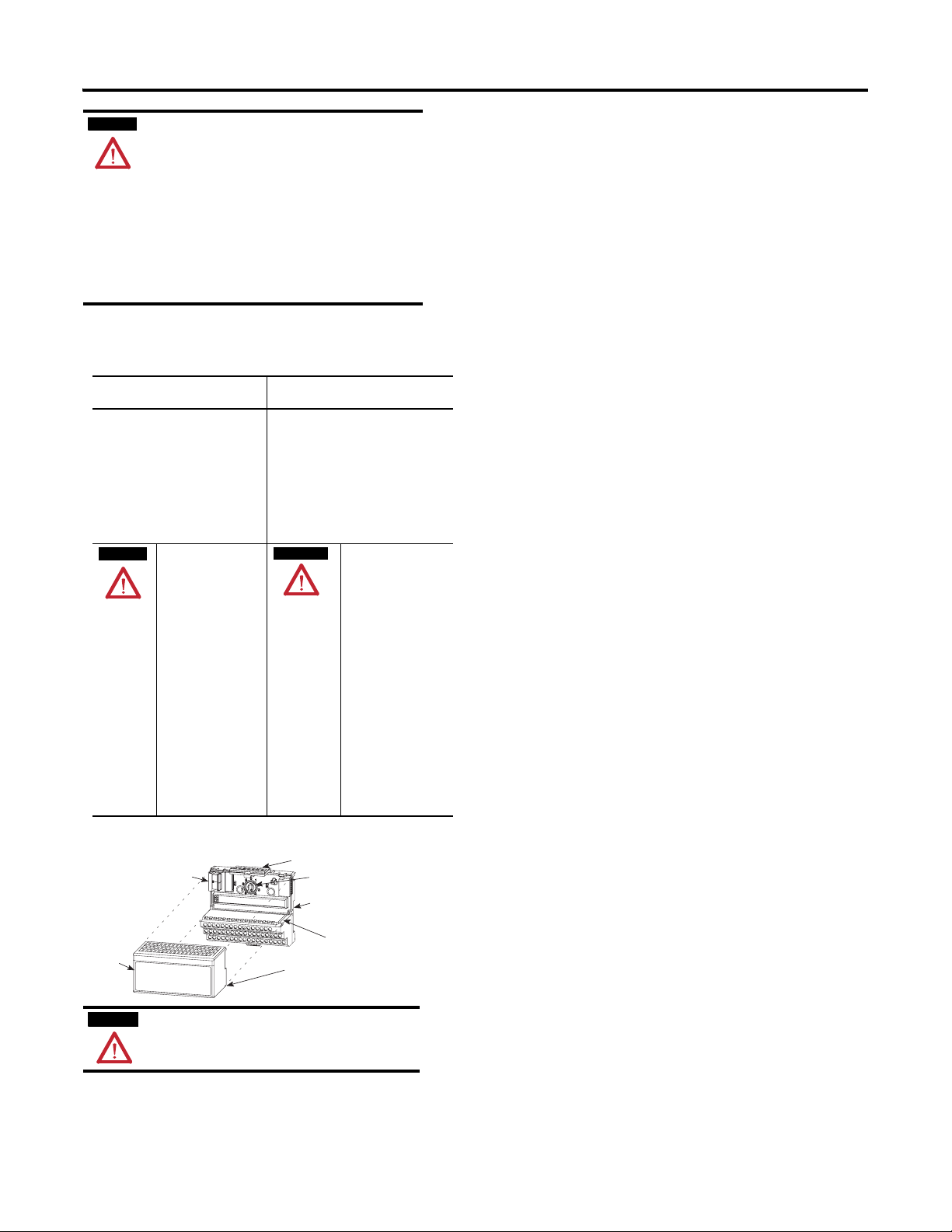
The module mounts on a 1794 terminal base.
1
2
6
5
1. Rotate the keyswitch (1) on the terminal base (2) clockwise to
position 2 as required for this type of module.
2. Make certain the flexbus connector (3) is pushed all the way to the
left to connect with the neighboring terminal base/adapter. You
cannot install the module unless the connector is fully
extended.
3. Make sure the pins on the bottom of the module are straight so
they will align properly with the connector in the terminal base.
4. Position the module (4) with its alignment bar (5) aligned with the
groove (6) on the terminal base.
5. Press firmly and evenly to seat the module in the terminal base
unit. The module is seated when the latching mechanism (7) is
locked into the module.
Connecting Wiring for the 1794-OB8EPXT, 1794-OB16PXT and
1794-IB10XOB6XT
1. Connect individual output wiring to numbered terminals on the
0…15 row as indicated in the accompanying table (1794-OB16P terminals 0…15, 1794-OB8EPXT- even numbered terminals 0…14).
2. Connect the associated -V output common to the corresponding
terminal on the 16-33 row (B) for each output as indicated in the
accompanying table. (Commons are internally connected
together.)
For 1794-OB8EPXT, connect associated output common to
odd-numbered terminals on row A or associated terminals on row
B.
3. For -IB10XOB6XT, connect the associated +V DC power lead of
the input device to the corresponding terminal on the 34-51 row
(C) for each input as indicated in the table . (The +V power
terminals of row (C) are internally connected together.)
4. For -IB10XOB6XT, connect the associated input device common
(3-wire devices only) and output device common to the
corresponding terminals on the 16-33 row. (B) for each input and
output as indicated in the table below. (Commons are internally
connected together.)
5. Connect +V DC power to terminal 34 on the 34…51 row (C).
6. Connect -V DC common to terminal 16 on the 16…33 row (B).
7. If daisychaining power to the next terminal base, connect a jumper
from terminal 51 (+V DC) on this base unit to terminal 34 on the
next base unit.
8. If continuing -V DC common to the next base unit, connect a
jumper from terminal 33 (common) on this base unit to terminal 16
on the next base unit.
Connecting Wiring for the 1794-IB16XT
1. Connect individual input wiring to numbered terminals on the
0…15 row (A) as indicated in the accompanying table.
2. Connect the associated +V DC power lead of the input device to
the corresponding terminal on the 34…51 row (C) for each input
as indicated in the accompanying table. (The +V power terminals
of row (C) are internally connected together.)
3. Connect the associated input common (3-wire devices only) to the
corresponding terminal on the 16…33 row. (B) for each input as
indicated in the accompanying table. (Commons are internally
connected together.)
4. Connect +V DC power to terminal 34 on the 34…51 row (C).
5. Connect DC common to terminal 16 on the 16…33 row (B).
6. If daisychaining power to the next terminal base, connect a jumper
from terminal 51 (+V DC) on this base unit to terminal 34 on the
next base unit.
7. If continuing DC common to the next base unit, connect a jumper
from terminal 33 (common) on this base unit to terminal 16 on the
next base unit.
Publication 1794-IN124A-EN-P - January 2009
Page 3
3
r
Wiring Connections for the 1794-OB16PXT (use with 1794-TB2, -TB3, or
-TB3S Terminal Base Units)
Output Output Terminal Common Terminal
Output 0 A-0 B-17
Output 1 A-1 B-18
Output 2 A-2 B-19
Output 3 A-3 B-20
Output 4 A-4 B-21
Output 5 A-5 B-22
Output 6 A-6 B-23
Output 7 A-7 B-24
Output 8 A-8 B-25
Output 9 A-9 B-26
Output 10 A-10 B-27
Output 11 A-11 B-28
Output 12 A-12 B-29
Output 13 A-13 B-30
Output 14 A-14 B-31
Output 15 A-15 B-32
+V dc C-34 thru C-51 (C-34 and C-51 for 1794-TB2)
Common B-16 thru B-33
Wiring Connections for the 1794-OB8EPXT
Output 1794-TB2, -TB3, TB3S 1794-TBN
Output
Terminal
Common
Terminal
Output
(1)
Terminal
Common
Terminal
(2)
Output 0 A-0 A-1/B-17 B-0 C-1
Output 1 A-2 A-3/B-18 B-2 C-3
Output 2 A-4 A-5/B-19 B-4 C-5
Output 3 A-6 A-7/B-20 B-6 C-7
Output 4 A-8 A-9/B-21 B-8 C-9
Output 5 A-10 A-11/B-22 B-10 C-11
Output 6 A-12 A-13/B-23 B-12 C-13
Output 7 A-14 A-15/B-24 B-14 C-15
+V dc C-34 thru C-51 (C-34 and C-51 for 1794-TB2, -TBN)
Common B-16 thru B-33 (B-16 and B-33 for 1794-TBN)
(1)
1794-TB2, -TB3, -TB3S - A-1, A-3, A-5, A-7, A-9, A-11, A-13 and A-15 are connected together
inside the module to 2 4V DC common.
(2)
1794-TBN - C-1, C-3, C-5, C-7, C-9, C-11, C-13 and C-15 are connected together inside the module
to 24V DC common.
Wiring Connections for 1794-IB16XT (use with 1794-TB3 or -TB3S Terminal
Base Units)
Input Input Terminal Voltage Terminal
Input 0 A-0 C-35 B-17
Input 1 A-1 C-36 B-18
Input 2 A-2 C-37 B-19
Input 3 A-3 C-38 B-20
Input 4 A-4 C-39 B-21
Input 5 A-5 C-40 B-22
Input 6 A-6 C-41 B-23
Input 7 A-7 C-42 B-24
Input 8 A-8 C-43 B-25
Input 9 A-9 C-44 B-26
Input 10 A-10 C-45 B-27
Input 11 A-11 C-46 B-28
Input 12 A-12 C-47 B-29
Input 13 A-13 C-48 B-30
Input 14 A-14 C-49 B-31
Input 15 A-15 C-50 B-32
+V dc C-34 thru C-51
Common B-16 thru B-33
(1)
3-wire devices use input, supply and common; 2-wire devices use input and supply
Common Terminal
(1)
Wiring Connections for the 1794-IB10XOB6XT
(1)
Input
Sink Input
Input 0 A-0 B-17 C-35
Input 1 A-1 B-18 C-36
Input 2 A-2 B-19 C-37
Input 3 A-3 B-20 C-38
Input 4 A-4 B-21 C-39
Input 5 A-5 B-22 C-40
Input 6 A-6 B-23 C-41
Input 7 A-7 B-24 C-42
Input 8 A-8 B-25 C-43
Input 9 A-9 B-26 C-44
Source Output
Output 0 A-10 B-27
Output 1 A-11 B-28
Output 2 A-12 B-29
Output 3 A-13 B-30
Output 4 A-14 B-31
Output 5 A-15 B-32
+V dc C-34 thru C-51 (internally connected together)
Common B-16 thru B-33 (internally connected together)
(1)
Two wire input devices use signal and supply terminals. Three wire devices use signal,
return and supply terminals.
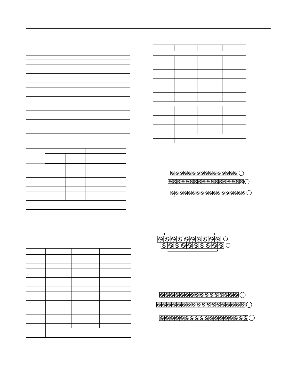
1794-TB2, -TB3 and -TB3S Terminal Base Wiring for 1794-OB8EPXT and
1794-OB16PXT
Signal Return Supply
0 1 2 3 4 5 6 7 8 9 10 11 12 13 14 15
17 18 19 20 21 22 23 24 25 26 27 28 29 30 31 32 33
16
-V
Common
35 36 37 38 39 40 41 42 43 44 45 46 47 48 49 50 51
34
Voltage
In +V
Connect -V (Supply Common) to terminal B-16
Connect +V (Supply +Voltage) to terminal C-34
(Use B-33 and C-51 for daisy-chaining to next terminal base unit.)
Total current draw through the terminal base is limited to 10A. Separate power
connections to each terminal base may be necessary.
Terminals 35 thru 50 not available on 1794-TB2
Outputs
Commons
Voltage
A
-V
Common
Voltage
Out +V
(1794-TB3 shown)
B
C
1794-TBN Terminal Base Wiring for the 1794-OB8EPXT
Even Numbered I/O Terminals 0 thru 14
COM
16
34
+V
Connect -V (Supply Common) to terminal B-16
Connect +V (Supply +Voltage) to terminal C-34
(Use B-33 and C-51 for daisy-chaining to next terminal base unit.)
Total current draw through the terminal base is limited to 10A. Separate powe
connections to each terminal base may be necessary.
4
2
0
1
6789101112
3
5
Odd Numbered I/O Terminals 1 thru 15
COM
14
33
13
B
51
15
C
+V
1794-TB3 and -TB3S Terminal Base Wiring for 1794-IB16XT
0 1 2 3 4 5 6 7 8 9 10 11 12 13 14 15
17 18 19 20 21 22 23 24 25 26 27 28 29 30 31 32 33
16
-V
Common
35 36 37 38 39 40 41 42 43 44 45 46 47 48 49 50 51
34
Voltage
In +V
Connect V common to terminals B-16
Connect +V to terminal C-34
Use B-33 and C-51 to daisy-chaining to the next terminal base unit
Inputs
Commons
Voltage
A
B
-V
Common
Voltage
Out +V
(1794-TB3 shown)
C
Publication 1794-IN124A-EN-P - January 2009
Page 4

4
1794-TB3 and -TB3S Terminal Base Wiring for the 1794-IB10XOB6XT
0 1 2 3 4 5 6 7 8 9 10 11 12 13 14 15
Inputs
Outputs
A
17 18 19 20 21 22 23 24 25 26 27 28 29 30 31 32 33
16
-V
Common
35 36 37 38 39 40 41 42 43 44 45 46 47 48 49 50 51
34
Commons
-V
Common
B
C
Voltage
In +V
-V (Supply Common) = Terminals B-16 and B-33
+V (Supply +Voltage In) = Terminals C-34 and C-51
(Use B-33 and C-51 for daisy-chaining to next terminal base unit)
Voltage
Voltage
Out +V
(1794-TB3 shown)
2 and 3-Wire Input Wiring for 1794-IB16XT, -IB10XOB6XT
A
0-15
16-33
B
C
34-51
= Sink input
A
B
C
= Common
= +V dc
2-Wire Device
(Sourcing Output)
3-Wire Device
(Sourcing Output)
Configuring Your Module
You configure your output/input module by setting bits in the
configuration word.
Configuration
Dec. 15 14 13 12 11 10 9 8 7 6 5 4 3 2 1 0
Oct. 17 16 15 14 13 12 11 10 7 6 5 4 3 2 1 0
1794-OB8EPXT
Read F7 F6 F5 F4 F3 F2 F1 F0 Reserved (see note)
Write Not used FR O7 O6 O5 O4 O3 O2 O1 O0
Write
1794-OB16PXT
Read Not used
Write O15 O14 O13 O12 O11 O10 O9 O8 O7 O6 O5 O4 O3 O2 O1 O0
Write
O31O30O29O28O27O26O25O24O23O22O21O20O19O18O17O
1794-OB
32P only
1794-IB16XT
Read 1I15I14I13I12I11I10I9I8I7I6I5I4I3I2I1I0
Read 2 C = Counter Input value of input 15
Write 1 Not used CF CR Not used Input Filter
12-15
1794-IB10XOB6XT
Read 1 Not used I9 I8 I7 I6 I5 I4 I3 I2 I1 I0
Write 2 Not used O5 O4 O3 O2 O1 0O
Write 3 Not used FT Not used
Where: O = Output - O0 corresponds t o output 0, O1 corresponds to output 1
F = Overload fault bits - 1 = fault presen t; 0 = no fault
FR = Fault reset bit - 1 = reset output; 0 = no change
I = Input
C = Counter value for input 15
CR = Counter reset
CF = Counter fast - where 1 = fast input (r aw data), 0 = standard input filtered data
FT = Input Filter Time for input channels
1794-OB16PXT uses outputs 0-3
NOTE: C, CR and CF not available when used w ith any series 1794-ASB or 1794-ASB2 remote I/O
adapter modules.
NOTE: The unused lower byte in read wor d 1 floats during operation. Do not use this byte for fault
status.
See Programming below.
Input Filter
0-11
Setting the Input Filter Time (1794-IB16XT, -IB10XOB6XT)
To set the input filter time, set the associated bits in the output image table
(complementary word) for the module .
15 14 13 12 11 10 9 8 7 6 5 4 3 2 1 0 Dec.
O:010
FT = 12-15
15 14 13 12 11 10 9 8 7 6 5 4 3 2 1 0 Dec.
O:010
1794-IB10XOB16XT
FT = 0-9
As an example for 1794-IB16XT, to increase the off-to-on filter time to 4 ms
for all inputs at address rack 1, module group 0, set bits and program as
shown below .
For 1794-IB10XOB6XT, increase the off-to-on filter time to 8 ms for all
inputs at address rack 1, module group 0, in configuration word 3, by
setting bits as shown below.
Write filter time on system startup.
I:000
00
1794-IB16XT
Write filter time on system startup.
I:000
00
16
1794-IB10XOB16XT
FLL
Fill File
Source
Destination #0:010
Length 1
76543210
100100
FLL
Fill File
Source
Destination #0:010
Length 1
12 11 10 9 8 7 6 5
101
Refer to the Input Filter time chart below for other bit settings.
Input Filter Time (1794-IB16XT)
Bits Description - Filter Time Filter Time
02 01 00 Inputs 0 thru 11 1794-IB16XT
05 04 03 Inputs 12 thru 15
0 0 0 Filter time 0 (default) 0.25 ms
0 0 1 Filter time 1 0.5 ms
0 1 0 Filter time 2 1 ms
0 1 1 Filter time 3 2 ms
1 0 0 Filter time 4 4 ms
1 0 1 Filter time 5 8 ms
1 1 0 Filter time 6 16 ms
1 1 1 Filter time 7 32 ms
Input Filter Time (1794-IB10XOB6XT)
Bits Description
10 09 08 Filter Time for Inputs Off to On/On to Off
0 0 0 Filter Time 0 0.25 ms
0 0 1 Filter Time 1 0.5 ms
0 1 0 Filter Time 2 1.0 ms
0 1 1 Filter Time 3 2.0 ms
1 0 0 Filter Time 4 4.0 ms
1 0 1 Filter Time 5 8.0 ms
1 1 0 Filter Time 6 16.0 ms
1 1 1 Filter Time 7 32.0 ms
FT = 0-11
1794-IB16XT
Write FT on
complement of
input module.
= 44 Octal or
36 Decimal
Write FT on
complement of
input module.
= 5 Octal or
5 Decimal
44706
44708
44707
44709
Publication 1794-IN124A-EN-P - January 2009
Page 5

5
Programming the 1794-OB8EPXT
If your program automatically checks for fault bits, bits 8…15 of read word
1 must be masked. This is a sample program for a module at rack address
1, group 0. Add similiar rungs to your program.
MVM
This rung masked bits 8 thru 15.
CMP
Compare
Expression
N9: < > 0
This rung turns on output if a fault occurs.
MASKED MOVE
Source
Mask
Destination
I:010
FF00
N9:0
O:000
( Out )
Resetting a Fault on the 1794-OB8EPXT
Faults can be reset 3 ways: press the fault reset button on the front of the
module; or toggle the output reset bit (write word 1, bit 08); or cycle
backplane power.
Using the Reset Button on the 1794-OB8EPXT
When you press the reset button, the fault indicator for the faulted output
turns off for about 1.2 s. After the delay, the faulted output attempts to turn
on. If the external condition causing the fault is corrected, the output will
remain on, the fault indicator is off, and the status indicator is on.
Specifications
Output Modules
Attribute 1794-OB8EPXT 1794-OB16PXT 1794-IB10XOB6XT
Number of outputs 8 (1 group of 8),
Module location Cat. No. 1794-TB2, -TB3,
On-state current 1.0 mA min. per channel
On-state voltage
range
nonisolated, sourcing
-TB3S, -TBN
2.0 A max. per channel
19.2 V DC min)
24 V DC nom.
31.2 V DC max.
Supply voltage 24V DC nom.
Voltage range 19.2V DC to 31.2V DC 10V DC to 31.2V DC 10 to 31.2 V DC (includes
Supply current 55mA @ 24V DC 35 mA @ 24V DC 15 mA @ 19.2 V DC
Output current
rating
Surge current 4.0 A for 10 ms,
Max. 2.0 A per output,
10.0
A max. per module
(for example, 8 outputs
@ 1.25 A, 5 outputs @
2.0
A, or similar
combinations totaling
10.0
A or less)
repeatable every 3 s
Off-state leakage 0.5 mA max.
On-state voltage
drop
Isolation voltage 50V (continuous), Basic
Output signal delay Off to On - 0.5 ms max.
0.2 V DC max. 0.5 V DC max. 1.0 V DC @2 A,
Insulation Type
No isolation between
individual channels
Type tested at 1500V AC
for 60 s, between field
side and system
On to Off - 1.0 ms max.
Flexbus current 80 mA 60 mA 35 mA
Power dissipation 5 W maximum @ 31.2 V DC5.0 W maximum @
16 nonisolated,
sourcing
Cat. No. 1794-TB2, -TB3, -TB3S
1.0 mA min. per
channel
500 mA max. per
channel
10 V DC min.
24 V DC nom.
31.2 V DC max.
8.0 A (16 outputs @
0.5A)
1.5 A for 50 ms,
repeatable every 2 s
50V (continuous), Basic
Insulation Type
No isolation between
individual channels
Type tested at 2550V
DC for 60 s, between
field side and system
31.2
V DC
6 nonisolated, sourcing
2.0 mA min.
8.0 mA nom. at 24V DC
11.0 mA max.
10 V DC min.
24 V DC nom.
31.2 V DC max.
5% AC ripple)
19 mA @ 24 V DC
8 mA @ 10V DC
25 mA @ 31.2V DC
2.0 A per output
10.0 A max. per module
4.0 A for 50 ms,
repeatable every 2 s
0.5 V DC@1 A max.
50V (continuous), Basic
Insulation Type
No isolation between
individual channels
Type tested at 1365V AC
for 60 s, between field
side and system
6.0 W maximum @ 31.2
V DC
Thermal dissipation Max. 17.1 BTU/hr @
Indicators (field side
indication, logic
driven)
Fusing Outputs are
(1)
Fusing is recommended. If fusing is desired, you must supply external fusing. Use SAN-O MQ4-3A or Litteolfuse
235-003 fuses.
31.2
V DC
8 yellow status
indicators
8 red fault indicators
electronically fused
Max. 17.0 BTU/hr @
31.2
V DC
16 yellow status
indicators
Outputs are
electronically
protected
Max. 20.3 BTU/hr @
31.2
V DC
6 yellow status
indicators
Module outputs are not
(1)
fused.
Input Modules
Attribute 1794-IB10XOB6XT 1794-IB16XT
Number of inputs 10, nonisolated, sinking 16 (1 group of 16), nonisolated,
Module location Cat. No. 1794-TB2, -TB3, -TB3S Cat. No. 1794-TB3, -TB3S Terminal
On-state current 2.0 mA min.
On-state voltage
range
8.0 mA nom. at 24V DC
11.0 mA max.
10 V DC min.
24 V DC nom.
31.2 V DC max.
Supply voltage 24V DC nom. 24V DC nom,
Voltage range 10 to 31.2 V DC (includes 5% AC
Supply current 15 mA @ 19.2 V DC
ripple)
19 mA @ 24 V DC
8 mA @ 10V DC
25 mA @ 31.2V DC
Off-state voltage 5.0 V DC max.
Off-state current 1.5 mA min.
Input impedance 4.8 KΩ
Isolation voltage 50V (continuous), Basic Insulation
Type
No isolation between individual
channels
Type tested at 1365V AC for 60 s,
between field side and system
Flexbus current 35 mA 30 mA
Power
dissipation
Thermal
dissipation
Indicators 10 yellow status indicators
6.0 W maximum @ 31.2 V DC 2 W max. @ 31.2V DC
Max. 20.3 BTU/hr @ 31.2 V DC Max 9.2 BTU/hr @ 31.2V DC
(Logix side indication, Logic driven)
sinking
Base Unit
2.0 mA min.
3.0 mA nom. at 24V DC
5.0 mA max.
10V DC to 31.2V DC
4 mA @ 24V DC
50V (continuous), Basic Insulation
Typ e
No isolation between individual
channels
Type tested at 850V AC for 60 s,
between field side and system
16 yellow status indicators
(field side indication, logic driven)
Publication 1794-IN124A-EN-P - January 2009
Page 6

General Specifications
Attribute Value
Terminal base screw
torque
Input filter time Refer to Input Filter Time setting tables.
Wire size Determined by installed terminal base
Wiring Category
Dimensions (with module
installed)
Enclosure type rating None (open-style)
Keyswitch position 2
Pilot Duty Rating 2A (-OB16PXT, -IB10XOB6XT, -OB8EPXT)
North American temp
code
IEC temp code T4
(1)
Use this Conductor Category information for planning conductor routing. Refer to Industrial Automation Wiring and
Grounding Guidelines, pub lication
Environmental
Attribute Value
Operating
temperature
Storage
temperature
Relative
humidity
Vibration IEC60068-2-6 (Test Fc, Operating):
Shock IEC60068-2-27 (Test Ea, Unpackaged shock):
Emissions CISPR 11:
ESD immunity IEC 61000-4-2:
Radiated RF
immunity
EFT/B immunity IEC 61000-4-4:
Surge transient
immunity
Conducted RF
immunity
Certifications (when product is marked)
Attribute Va lue
c-UL-us
CE
Determined by installed terminal base
(1)
2 - on signal ports
94H x 94W x 69D mm
3.7H x 3.7W x 2.7D in.
T4A
T4 (-OB8EPXT, -IB10XOB6XT)
1770-4.1.
IEC 60068-2-1 (Test Ad, Operating Cold),
IEC 60068-2-2 (Test Bd, Operating Dry Heat),
IEC 60068-2-14 (Test Nb, Operating Thermal Shock):
-20 …70 °C (-4…158 °F)
IEC 60068-2-1 (Test Ab, Un-packaged Non-operating Cold),
IEC 60068-2-2 (Test Bb, Un-packaged Non-operating Dry Heat),
IEC 60068-2-14 (Test Na, Un-packaged Non-operating Thermal Shock):
–40 to 85 °C (–40 to 185 °F)
IEC 60068-2-30 (Test Db, Unpackaged Damp Heat):
5…95% noncondensing
5 g @ 10-500 Hz
Operating 30 g
Non-operating 50 g
Group 1, Class A (with appropriate enclosure)
6 kV contact discharges
8 kV air discharges
IEC 61000-4-3:
10V/m with 1 kHz sine-wave 80% AM from 80…2000 MHz
10V/m with 200 Hz 50% Pulse 100% AM at 900 MHz
10V/m with 200 Hz 50% Pulse 100% AM at 1890 MHz
3V/m with 1 kHz sine-wave 80% AM from 2000…2700 MHz
±2kV at 5kHz on signal ports
IEC 61000-4-5:
±1 kV line-line(DM) and ±2 kV line-earth(CM) on signal ports
IEC 61000-4-6:
10V rms with 1 kHz sine-wave 80% AM from 150 kHz…80 MHz
(1)
UL Listed Industrial Control Equipment, certified f or US and Canada. See UL File
E65584.
UL Listed for Class I, Division 2 Group A,B,C,D Hazardous Locations, certified for
U.S. and Canada. See UL File E194810.
European Union 2004/108/EC EMC Directive, compli ant with:
EN 61326-1; Meas./Control/Lab., Industrial Requirements
EN 61000-6-2; Industrial Immunity
EN 61000-6-4; Industrial Emissions
EN 61131-2; Programmable Controllers (Cla use 8, Zone A & B)
Certifications (when product is marked)
C-Tick
Ex
TÜV
(1)
See the Product Certification link at http://www.ab.com for Declaration of Conformity, Certifica tes, and other
certification details.
Australian Radiocommunications Act, compliant with:
AS/NZS CISPR 11; Industrial Emissions
European Union 94/9/EC ATEX Directive, compliant with:
EN 60079-15; Potentially Explosive Atmospheres, Pr otection "n" (II 3 G Ex nA IIC T4
X)
EN 60079-0; General Requirements (Zone 2 )
TÜV Certified for Functional Safety:
up to and including SIL 2
(1)
Publication 1794-IN124A-EN-P - January 2009 6 PN-38723
Copyright © 2009 Rockwell Automation, Inc. All rights reserved.
 Loading...