

Rockwell Automation 1794-OB8, 1794-OB16P, 1794-OB8EP, 1794-OB16, 1794-OB32P Installation Instructions Manual
Page 1
Installation Instructions
FLEX I/O Digital DC Output Modules
Catalog numbers 1794-OB8, 1794-OB8EP, 1794-OB16,
1794-OB16P, 1794-OB32P
Table of Contents
Topic Page
Important User Information 2
Environment and Enclosure 3
Preventing Electrostatic Discharge 3
European Hazardous Location Approval 3
North American Hazardous Location Approval 7
Install Your FLEX I/O AC Digital Output Module 8
Connect Wiring for 1794-OB8, 1794-OB8EP, 1794-OB16, and 1794-OB16P 9
Connect Wiring for the 1794-OB32P 11
Configuring your 1794-OB8EP Output Module 14
Configure the 1794-OB8, 1794-OB16, 1794-OB16P, 1794-OB32P Modules 15
Specifications 16
Page 2
2 FLEX I/O Digital DC Output Modules
Important User Information
Solid-state equipment has operational characteristics differing from those of electromechanical
equipment. Safety Guidelines for the Application, Installation, and Maintenance of Solid-State Controls
(Publication SGI-1.1
http://www.rockwellautomation.com/literature/
state equipment and hard-wired electromechanical devices. Because of this difference, and also because
of the wide variety of uses for solid state equipment, all persons responsible for applying this equipment
must satisfy themselves that each intended application of this equipment is acceptable.
In no event will Rockwell Automation, Inc. be responsible or liable for indirect or consequential damages
resulting from the use or application of this equipment.
The examples and diagrams in this manual are included solely for illustrative purposes. Because of the
many variables and requirements associated with any particular installation, Rockwell Automation, Inc.
cannot assume responsibility or liability for actual use based on the examples and diagrams.
No patent liability is assumed by Rockwell Automation, Inc. with respect to use of information, circuits,
equipment, or software described in this manual.
available from your local Rockwell Automation Sales Office or online at
) describes some important differences between solid
Reproduction of the contents of this manual, in whole or in part, without written permission of Rockwell
Automation, Inc. is prohibited.
Throughout this manual we use notes to make you aware of safety considerations.
WARNING: Identifies information about practices or circumstances that can cause an
explosion in a hazardous environment, which may lead to personal injury or death,
property damage, or economic loss.
ATTENTION: Identifies information about practices or circumstances that can lead to
personal injury or death, property damage, or economic loss. Attentions help you
identify a hazard, avoid a hazard, and recognize the consequences.
IMPORTANT Identifies information that is critical for successful application and understanding of
the product.
Publication 1794-IN094D-EN-P - July 2018
Page 3
Environment and Enclosure
ATTENTION: This equipment is intended for use in a Pollution Degree 2
industrial environment, in overvoltage Category II applications (as defined in
EN/IEC 60664-1), at altitudes up to 2000 m (6562 ft) without derating.
This equipment is not intended for use in residential environments and may not
provide adequate protection to radio communication services in such
environments.
This equipment is supplied as open-type equipment for indoor use. It must be
mounted within an enclosure that is suitably designed for those specific
environmental conditions that will be present and appropriately designed to
prevent personal injury resulting from accessibility to live parts. The enclosure
must have suitable flame-retardant properties to prevent or minimize the spread
of flame, complying with a flame spread rating of 5VA or be approved for the
application if nonmetallic. The interior of the enclosure must be accessible only
by the use of a tool. Subsequent sections of this publication may contain more
information regarding specific enclosure type ratings that are required to
comply with certain product safety certifications.
FLEX I/O Digital DC Output Modules 3
In addition to this publication, see the following:
• Industrial Automation Wiring and Grounding Guidelines, publication
1770-4.1
• NEMA Standard 250 and EN/IEC 60529, as applicable, for explanations of
the degrees of protection provided by enclosures.
, for more installation requirements.
Preventing Electrostatic Discharge
ATTENTION: This equipment is sensitive to electrostatic discharge, which can
cause internal damage and affect normal operation. Follow these guidelines
when you handle this equipment:
• Touch a grounded object to discharge potential static.
• Wear an approved grounding wriststrap.
• Do not touch connectors or pins on component boards.
• Do not touch circuit components inside the equipment.
• Use a static-safe workstation, if available.
• Store the equipment in appropriate static-safe packaging when not in use.
Publication 1794-IN094D-EN-P - July 2018
Page 4
4 FLEX I/O Digital DC Output Modules
ATTENTION: This product is grounded through the DIN rail to chassis ground.
Use zinc plated chromate-passivated steel DIN rail to assure proper grounding.
The use of other DIN rail materials (for example, aluminum or plastic) that can
corrode, oxidize, or are poor conductors, can result in improper or intermittent
grounding. Secure DIN rail to mounting surface approximately every 200 mm
(7.8 in.) and use end-anchors appropriately. Be sure to ground the DIN rail
properly.
Refer to Industrial Automation Wiring and Grounding Guidelines, Rockwell
Automation publication 1770-4.1
ATTENTION: If this equipment is used in a manner not specified by the
manufacturer, the protection provided by the equipment may be impaired.
, for more information.
ATTENTION: If this equipment is used in a manner not specified by the
manufacturer, the protection provided by the equipment may be impaired.
ATTENTION: Read this document and the documents listed in the Additional
Resources section about installation, configuration, and operation of this
equipment before you install, configure, operate, or maintain this product.
Users are required to familiarize themselves with installation and wiring
instructions in addition to requirements of all applicable codes, laws, and
standards.
ATTENTION: Installation, adjustments, putting into service, use, assembly,
disassembly, and maintenance are required to be carried out by suitably
trained personnel in accordance with applicable code of practice.
In case of malfunction or damage, no attempts at repair should be made. The
module should be returned to the manufacturer for repair. Do not dismantle the
module.
ATTENTION: Use only a soft dry anti-static cloth to wipe down equipment. Do
not use any cleaning agents.
Publication 1794-IN094D-EN-P - July 2018
Page 5
FLEX I/O Digital DC Output Modules 5
WARNING: When you insert or remove the module while backplane power
is on, an electric arc can occur. This could cause an explosion in hazardous
location installations.
Be sure that power is removed or the area is nonhazardous before
proceeding. Repeated electric arcing causes excessive wear to contacts on
both the module and its mating connector. Worn contacts may create
electrical resistance that can affect module operation.
WARNING: If you insert or remove the module while backplane power is on,
an electric arc can occur. This could cause an explosion in hazardous location
installations.
Be sure that power is removed or the area is nonhazardous before
proceeding.
At the end of its life, this equipment should be collected separately from any
unsorted municipal waste.
Publication 1794-IN094D-EN-P - July 2018
Page 6
6 FLEX I/O Digital DC Output Modules
European Hazardous Location Approval
Approved for 1794-OB8, 1794-OB8EP, 1794-OB16 and 1794-OB16P modules..
The following applies to products marked II 3 G:
Are Equipment Group II, Equipment Category 3, and comply with the Essential Health and
Safety Requirements relating to the design and construction of such equipment given in
Annex II to EU Directive 2014/34/EU. See the EU Declaration of Conformity at
http://www.rockwellautomation.com/global/certification/overview.page
The type of protection is II 3G Ex nA IIC T3 Gc according to EN 60079-15.
Comply to Standards EN 60079-0:2012, EN 60079-15:2010, reference certificate number
LCIE 01 ATEX 6020 X.
Are intended for use in areas in which explosive atmospheres caused by gases, vapors,
mists, or air are unlikely to occur, or are likely to occur only infrequently and for short
periods. Such locations correspond to Zone 2 classification according to ATEX directive
2014/34/EU.
for details.
WARNING: Observe the following additional certification requirements:
• This equipment is not resistant to sunlight or other sources of
UV radiation.
• This equipment shall be mounted in an ATEX/IECEx Zone 2 certified
enclosure with a minimum ingress protection rating of at least IP54 (in
accordance with EN/IEC 60079-15) and used in an environment of not
more than Pollution Degree 2 (as defined in EN/IEC 60664-1) when
applied in Zone 2 environments. The enclosure must be accessible only by
the use of a tool.
• This equipment shall be used within its specified ratings defined by
Rockwell Automation.
• The instructions in the user manual shall be observed.
• This equipment must be used only with ATEX certified Rockwell
Automation backplanes.
• Earthing is accomplished through mounting of modules on rail.
• Devices shall be used in an environment of not more than Pollution
Degree 2.
• Enclosure must be marked with the following: “Warning - Do not open
when energized.” After installation of equipment into the enclosure,
access to termination compartments shall be dimensioned so that
conductors can be readily connected.
Publication 1794-IN094D-EN-P - July 2018
Page 7
FLEX I/O Digital DC Output Modules 7
North American Hazardous Location Approval
The 1794-OB8, 1794-OB8EP, 1794-OB16, 1794-OB16P module is Hazardous Location approved:
The following information applies when
operating this equipment in hazardous locations:
Products marked "CL I, DIV 2, GP A, B, C, D" are suitable for
use in Class I Division 2 Groups A, B, C, D, Hazardous
Locations and nonhazardous locations only. Each product is
supplied with markings on the rating nameplate indicating
the hazardous location temperature code. When combining
products within a system, the most adverse temperature
code (lowest "T" number) may be used to help determine
the overall temperature code of the system. Combinations
of equipment in your system are subject to investigation by
the local Authority Having Jurisdiction at the time of
installation.
WARNING:
EXPLOSION HAZARD
• Do not disconnect equipment unless
power has been removed or the area is
known to be nonhazardous.
• Do not disconnect connections to this
equipment unless power has been
removed or the area is known to be
nonhazardous. Secure any external
connections that mate to this equipment
by using screws, sliding latches,
threaded connectors, or other means
provided with this product.
• Substitution of components may impair
suitability for Class I, Division 2.
Informations sur l’utilisation de cet équipement
en environnements dangereux:
Les produits marqués "CL I, DIV 2, GP A, B, C, D" ne
conviennent qu'à une utilisation en environnements de Classe
I Division 2 Groupes A, B, C, D dangereux et non dangereux.
Chaque produit est livré avec des marquages sur sa plaque
d'identification qui indiquent le code de température pour les
environnements dangereux. Lorsque plusieurs produits sont
combinés dans un système, le code de température le plus
défavorable (code de température le plus faible) peut être
utilisé pour déterminer le code de température global du
système. Les combinaisons d'équipements dans le système
sont sujettes à inspection par les autorités locales qualifiées
au moment de l'installation.
WARNING:
RISQUE D’EXPLOSION
• Couper le courant ou s'assurer que
l'environnement est classé non dangereux
avant de débrancher l'équipement.
• Couper le courant ou s'assurer que
l'environnement est classé non dangereux
avant de débrancher les connecteurs. Fixer
tous les connecteurs externes reliés à cet
équipement à l'aide de vis, loquets
coulissants, connecteurs filetés ou autres
moyens fournis avec ce produit.
• LLa substitution de composants peut rendre
cet équipement inadapté à une utilisation en
environnement de Classe I, Division 2.
Publication 1794-IN094D-EN-P - July 2018
Page 8
8 FLEX I/O Digital DC Output Modules
6
1
7
5
4
3
2
6
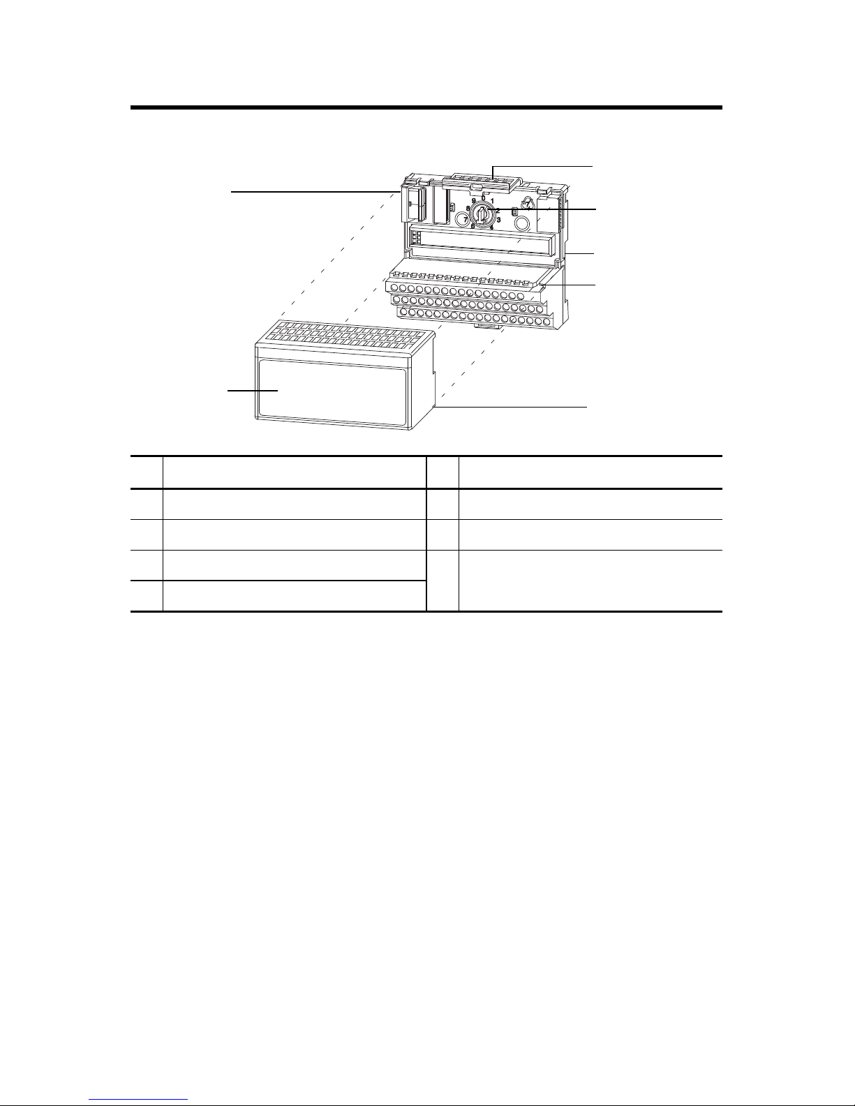
Install Your FLEX I/O AC Digital Output Module
Description Description
1 Flexbus connector 5 Groove
2 Latching mechanism 6 Alignment bar
3 Keyswitch 7 Module
4 Terminal base
The module mounts on a 1794 terminal base.
1. Rotate the keyswitch (3) on the terminal base (4) clockwise to position 2 as
required for this type of module.
2. Make sure the Flexbus connector (1) is pushed all the way to the left to connect
with the neighboring terminal base/adapter.
You cannot install the module unless the connector is fully extended.
3. Make sure the pins on the bottom of the module are straight so they will align
properly with the connector in the terminal base.
4. Position the module (7) with its alignment bar (6) aligned with the groove (5) on
the terminal base.
5. Press firmly and evenly to seat the module in the terminal base unit. The module
is seated when the latching mechanism (2) is locked into the module.
Publication 1794-IN094D-EN-P - July 2018
Page 9

FLEX I/O Digital DC Output Modules 9
Connect Wiring for 1794-OB8, 1794-OB8EP, 1794-OB16, and 1794-OB16P
1. Connect individual output wiring to numbered terminals on the 0-15 row (A) as
indicated in the table below 1794-OB8 – Terminals 0...7; 1794-OB16 and
1794-OB16P – terminals 0...15; 1794-OB8EP – even numbered terminals
0...14.
2. Connect the associated -V output common to the corresponding terminal on the
16…33 row (B) for each output as indicated in the table below. Commons are
internally connected together.
1794-OB8EP – connect associated output common to odd-numbered terminals
on row A or associated terminals on row (B).
3. Connect +V DC power to terminal 34 on the 34…51 row (C).
4. Connect -V DC common to terminal 16 on the 16…33 row (B).
5. If daisychaining power to the next terminal base, connect a jumper from terminal
51 (+V DC) on this base unit to terminal 34 on the next base unit.
6. If continuing -V DC common to the next base unit, connect a jumper from
terminal 33 (common) on this base unit to terminal 16 on the next base unit.
Wiring Connections for 1794-OB8, 1794-OB16, and 1794-OB16P
used with 1794-TB2, 1794-TB3, or 1794-TB3S Terminal Base Unit
Output
Output 0 A-0 B-17
Output 1 A-1 B-18
Output 2 A-2 B-19
Output 3 A-3 B-20
Output 4 A-4 B-21
Output 5 A-5 B-22
Output 6 A-6 B-23
Output 7 A-7 B-24
Output 8 A-8 B-25
Output 9 A-9 B-26
Output 10 A-10 B-27
Output 11 A-11 B-28
Output 12 A-12 B-29
Output 13 A-13 B-30
Output 14 A-14 B-31
Output 15 A-15 B-32
+V DC C-34…C-51 (C-34 and C-51 for 1794-TB2)
Common B-16…B-33
(1)
Output Terminal Common Terminal
(1)
1794-OB8 – Outputs 0...7; 1794-OB16 and 1794-OB16P – Outputs 0...15
Publication 1794-IN094D-EN-P - July 2018
Page 10

10 FLEX I/O Digital DC Output Modules
Wiring Connections for 1794-OB8EP
1794-TB2, 1794-TB3, 1794-TB3S 1794-TBN
Output Output Terminal Common
Terminal
(1)
Output Terminal Common
Terminal
(2)
Output 0 A-0 A-1/B-17 B-0 C-1
Output 1 A-2 A-3/B-18 B-2 C-3
Output 2 A-4 A-5/B-19 B-4 C-5
Output 3 A-6 A-7/B-20 B-6 C-7
Output 4 A-8 A-9/B-21 B-8 C-9
Output 5 A-10 A-11/B-22 B-10 C-11
Output 6 A-12 A-13/B-23 B-12 C-13
Output 7 A-14 A-15/B-24 B-14 C-15
+V DC C-34…C-51 (C-34 and C-51 for 1794-TB2, 1794-TBN)
Common B-16…B-33 (B-16 and B-33 for 1794-TBN)
(1)
1794-TB2, 1794-TB3,1794 -TB3S – A-1, A-3, A-5, A-7, A-9, A-11, A-13, and A-15 are connected together inside the
module to 24V DC common.
(2)
1794-TBN – C-1, C-3, C-5, C-7, C-9, C-11, C-13, and C-15 are connected together inside the module to 24V DC common.
1794-TB2, 1794-TB3, and 1794-TB3S Terminal Base Wiring for 1794-OB8,
1794-OB8EP, 1794-OB16, and 1794-OB16P
0 1 2 3 4 5 6 7 8 9 10 11 12 13 14 15
17 18 19 20 21 22 23 24 25 26 27 28 29 30 31 32 33
16
-V
Common
Voltage
In +V
Connect -V (Supply Common) to terminal B-16
Connect +V (Supply +Voltage) to terminal C-34
(Use B-33 and C-51 for daisy-chaining to next terminal base unit.)
Total current draw through the terminal base is limited to 10A. Separate power
connections to each terminal base may be necessary.
35 36 37 38 39 40 41 42 43 44 45 46 47 48 49 50 51
34
Terminals 35 thru 50 not available on 1794-TB2
Outputs
Commons
Voltage
A
B
-V
Common
Voltage
Out +V
(1794-TB3 shown)
C
Publication 1794-IN094D-EN-P - July 2018
Page 11

FLEX I/O Digital DC Output Modules 11
1794-TBN Terminal Base Wiring for 1794-OB8EP
Even Numbered I/O Terminals 0 thru 14
COM
16
0
34
1
+V
Connect -V (Supply Common) to terminal B-16
Connect +V (Supply +Voltage) to terminal C-34
(Use B-33 and C-51 for daisy-chaining to next terminal base unit.)
Total current draw through the terminal base is limited to 10A. Separate power
connections to each terminal base may be necessary.
4
2
Odd Numbered I/O Terminals 1 thru 15
3
5
6789101112
13
COM
14
33
15
B
51
C
+V
Connect Wiring for the 1794-OB32P
1. Connect individual output wiring (OUT0…OUT15) to numbered terminals on
the 0…15 row (A) as indicated in the Wiring Connections for 1794-OB32P
table.
2. Connect the associated power to the +V1 terminal (35, 37, 39, or 41) on the
34…51 row (C) as indicated in the Wiring Connections for 1794-OB32P
table.
3. Connect the associated output common (-V1)for OUT0 to OUT15 to COM1
(terminal 36, 38, 40, or 42) on the 34…51 row (C).
4. Connect individual output wiring (OUT16…OUT31) to numbered terminals
on the 16…33 row (B) as indicated in the Wiring Connections for 1794-OB32P
table.
5. Connect the associated power to the +V2 terminal (43, 45, 47, or 49) on the
34…51 row (C) as indicated in the Wiring Connections for 1794-OB32P
table.
6. Connect the associated output common (-V2) for OUT16…OUT31 to COM2
(terminals 44, 46, 48, or 50) on the 34…51 row (C).
7. If continuing power to the next terminal base, connect a jumper from terminal
35, 37, 39, or 41 (+V1) and 43, 45, 37, or 49 (+V2) on this base unit to the power
terminal on the next base unit.
8. If continuing output common return to the next base unit, connect a jumper
from terminal 36, 38, 40 or 42 (COM1) and 44, 46, 48 or 50 (COM2) on this
base unit to common on the next base unit. Refer to the installation instructions
for the next type of terminal base unit.
Publication 1794-IN094D-EN-P - July 2018
Page 12

12 FLEX I/O Digital DC Output Modules
IMPORTANT
Total current draw through terminal base connection is limited to 10 A.
Separate power connections to each terminal base may be necessary.
Wiring Connections for 1794-OB32P
used with 1794-TB32 or 1794-TB32S Terminal Base Unit
Output Output Terminal Common Power
Output 0 A-0 Connect common to
Output 1 A-1
Output 2 A-2
Output 3 A-3
Output 4 A-4
Output 5 A-5
Output 6 A-6
Output 7 A-7
Output 8 A-8
Output 9 A-9
Output 10 A-10
Output 11 A-11
Output 12 A-12
Output 13 A-13
Output 14 A-14
Output 15 A-15
Output 16 B-17 Connect common to
Output 17 B-18
terminals 36, 38, 40, and 42
terminals 44, 46, 48, and 50
Connect power to terminals
35, 37, 39, and 41
Connect power to terminals
43, 45, 47, and 49
Output 18 B-19
Output 19 B-20
Output 20 B-21
Output 21 B-22
Output 22 B-23
Output 23 B-24
Output 24 B-25
Output 25 B-26
Output 26 B-27
Output 27 B-28
Publication 1794-IN094D-EN-P - July 2018
Page 13

FLEX I/O Digital DC Output Modules 13
Wiring Connections for 1794-OB32P
used with 1794-TB32 or 1794-TB32S Terminal Base Unit
Output Output Terminal Common Power
Output 28 B-29 Connect common to
Output 29 B-30
terminals 44, 46, 48, and 50
Connect power to terminals
43, 45, 47, and 49
Output 30 B-31
Output 31 B-32
For Outputs 0...15, use +V1 and COM1
+V1 DC power Power terminals 35, 37, 39, and 41
Com1 DC Return Common terminals 36, 38, 40, and 42
For Outputs 16...31, use +V2 and COM2
+V2 DC power Power terminals 43, 45, 47, and 49
Com2 DC Return Common terminals 44, 46, 48, and 50
1794-TB32 and 1794-TB32S Terminal Base Wiring for 1794-OB32PI
0 1 2 3 4 5 6 7 8 9 10 11 12 13 14 15
A
Outputs
17 18 19 20 21 22 23 24 25 26 27 28 29 30 31 32 33
16
B
NC NC
35 36 37 38 39 40 41 42 43 44 45 46 47 48 49 50 51
34
+V1 COM1 +V1 COM1 +V1 COM1 +V1 COM1 +V2 COM2 +V2 COM2 +V2 COM2 +V2 COM2 NC
NC
+V1 = Terminals 35, 37, 39 and 41
+V2 = Terminals 43, 45, 47 and 49
COM1 = Terminals 36, 38, 40 and 42
COM2 = Terminals 44, 46, 48 and 50
NC = No connections (terminals 16, 33, 34 and 51)
Outputs
(1794-TB32 shown)
C
Publication 1794-IN094D-EN-P - July 2018
Page 14

14 FLEX I/O Digital DC Output Modules
Configuring your 1794-OB8EP Output Module
Configure your output module by setting bits in the configuration word
Image Table Memory Map for the 1794-OB8EP Module
Dec 1514131211109876 543210
Oct 17161514131211107 6 5 4 3 2 1 0
Read F7 F6 F5 F4 F3 F2 F1 F0 Reserved
(1)
Write Not used FR O7 O6 O5 O4 O3 O2 O1 O0
Where: O = Output – O0 corresponds to output 0, 01 corresponds to output 1, and so on.
F = Overload fault bit – 1 = fault present; 0 = no fault
FR = Fault reset bit – 1 = reset output; 0 = no change
(1)
The unused lower byte in read word 1 floats during operation. Do not use this byte for fault status. See Program the 1794-OB8EP.
Program the 1794-OB8EP
If your program automatically checks for fault bits, bits 8…15 of read word 1 must be
masked. This is a sample program for a module at rack address 1, group 0. Add similar
rungs to your program.
MVM
This rung masked bits 8 thru 15.
CMP
Compare
Expression
N9: < > 0
MASKED MOVE
Source
Mask
Destination
I:010
FF00
N9:0
O:000
( Out )
This rung turns on output if a fault occurs.
Reset a Fault on the 1794-OB8EP – Faults can be reset 3 ways: Press the fault reset
button on the front of the module; or toggle the output reset bit (write word 1, bit 08); or
cycle backplane power.
Use the Reset Button on the 1794-OB8EP – When you press the reset button, the fault
indicator for the faulted output turns off for about 1.2 s. After the delay, the faulted output
attempts to turn on. If the external condition causing the fault is corrected, the output will
remain on, the fault indicator is off, and the status indicator is on.
Publication 1794-IN094D-EN-P - July 2018
Page 15

FLEX I/O Digital DC Output Modules 15
Configure the 1794-OB8, 1794-OB16, 1794-OB16P,
1794-OB32P Modules
Configure your output module by setting bits in the configuration word (Word 3).
Image Table Memory Map – 1794-OB8, 1794-OB16, 1794-OB16P, and 1794-OB32 Modules
Dec 1514131211109876543210
Oct 17161514131211107 6 5 4 3 2 1 0
Read Not used
Write O15O14O13O12O11O10O9O8O7O6O5O4O3O2O1O0
Write
1794-OB32P
only
Where: O = Output – O0 corresponds to output 0, 01 corresponds to output 1, and so on.
O31 O30 O29 O28 O27 O26 O25 O24 O23 O22 O21 O20 O19 O18 O17 O16
1794-OB8 uses outputs 0...7; 1794-OB16 and 1794-OB16P use outputs 0...15; 1794-OB32P uses
outputs 0...31.
Publication 1794-IN094D-EN-P - July 2018
Page 16

16 FLEX I/O Digital DC Output Modules
Specifications
Specifications – 1794-OB8
Attribute Value
Number of outputs 8, current, sourcing
Recommended terminal base unit 1794-TB2, 1794-TB3, 1794-TB3S,1794-TB3K, 1794-TB3SK
On-state voltage, output min 10V DC
On-state voltage, output nom 24V DC
On-state voltage, output max 31.2V DC
Output current rating 4 A (8 outputs @ 0.5 A)
On-state current, output, min 1.0 mA per channel
On-state current, output, max 500 mA per channel
On-state voltage drop, max 0.5V DC
Surge current 2 A for 50 ms, repeatable every 2 seconds
Off-state leakage current, max 0.5 mA
Isolation voltage 50V (continuous), Basic Insulation Type
Tested at 850V DC for 1 s, between user and system
No isolation between individual channels
(1)
Output signal delay
Off to On
On to Off
FlexBus current 60 mA @ 5V DC
Power dissipation, max 3.3 W @ 31.2V DC
Thermal dissipation, max 11.2 BTU/hr @ 31.2V DC
Fusing Module outputs are not fused. Fusing is recommended. If fusing
(1)
Delay time is the time from the receipt of an output on or off command to the output actually turning on or off.
0.5 ms
1.0 ms
is desired, you must provide external fusing. Use SAN-O
MQ4-800mA fuses.
Specifications – 1794-OB8EP
Attribute Value
Number of outputs 8, current, sourcing
Recommended terminal base unit 1794-TB2, 1794-TB3, 1794-TB3S, 1794-TBN, 1794-TB3K,
On-state voltage, output min 19.2V DC
Publication 1794-IN094D-EN-P - July 2018
1794-TB3SK, 1794-TBNK
Page 17

FLEX I/O Digital DC Output Modules 17
Time - ms
01020304050
0
5
10
15
20
Surge Current - A
Output minimum Surge Current
Specifications – 1794-OB8EP
Attribute Value
On-state voltage, output nom 24V DC
On-state voltage, output max 31.2V DC
Output current rating 2.0 A max per output
10.0 A max per module (8 outputs @ 1.25 A, 5 outputs @ 2.0 A,
or similar combinations totaling 10.0 A or less)
On-state current, output, min 1.0 mA per channel
On-state current, output, max 2.0 A per channel
On-state voltage drop, max 0.2V DC
Surge current 4 A for 50 ms, repeatable every 3 seconds
Off-state leakage current, max 0.5 mA
Isolation voltage 50V (continuous), Basic Insulation Type
Tested at 850V DC for 1 s, between field side and system
No isolation between individual channels
(1)
Output signal delay
Off to On
On to Off
0.1 ms
0.1 ms
FlexBus current 73 mA @ 5V DC
Power dissipation, max 5.5 W @ 31.2V DC
Thermal dissipation, max 18.8 BTU/hr @ 31.2V DC
Fusing Outputs are electronically fused
(1)
Delay time is the time from the receipt of an output on or off command to the output actually turning on or off.
Surge Current for 1794-OB8EP
Publication 1794-IN094D-EN-P - July 2018
Page 18

18 FLEX I/O Digital DC Output Modules
Specifications – 1794-OB16 and 1794-OB16P
Attribute 1794-OB16 1794-OB16P
Number of outputs 16, current, sourcing
Recommended terminal base unit 1794-TB2,1794-TB3,1794-TB3S, 1794-TB3K, 1794-TB3SK
On-state voltage, output min 10V DC
On-state voltage, output nom 24V DC
On-state voltage, output max 31.2V DC (see Derating Curve for 1794-OB16P
Output current rating 8.0 A (16 outputs @ 0.5 A)
On-state current, output, min 1.0 mA per channel
On-state current, output, max 500 mA per channel
On-state voltage drop, max 0.5V DC
Surge current 2 A for 50 ms, repeatable every 2
seconds
Off-state leakage current, max 0.5 mA
Isolation voltage 50V (continuous), Basic Insulation
Type
Tested at 850V DC for 1 s between
user and system
No isolation between individual
channels
Output signal delay
Off to On
On to Off
FlexBus current 80 mA @ 5V DC 60 mA @ 5V DC
(1)
0.5 ms
1.0 ms
1.5 A for 50 ms, repeatable
every 2 seconds
50V (continuous), Basic
Insulation Type
Type tested at 2121V DC for 60
s, between field side and
system
No isolation between
individual channels
)
Power dissipation, max 5.3 W @ 31.2V DC 5.0 W @ 31.2V DC
Thermal dissipation, max 18.1 BTU/hr @ 31.2V DC 17.0 BTU/hr @ 31.2V DC
Fusing Module outputs are not fused.
(1)
Delay time is the time from the receipt of an output on or off command to the output actually turning on or off.
Publication 1794-IN094D-EN-P - July 2018
Fusing is recommended. If fusing is
desired, you must provide external
fusing. Use SAN-O
MQ4-800 mA fuses.
Outputs are electronically
protected.
Page 19

FLEX I/O Digital DC Output Modules 19
Specifications – 1794-OB32P
Attribute Value
Number of outputs 32, current, sourcing
Recommended terminal base unit 1794-TB32, 1794-TB32S
On-state voltage, output min 10V DC
On-state voltage, output nom 24V DC
On-state voltage, output max 31.2V DC
Output current rating 14.0 A max per module (6 A total for channels 0...15; 8 A total for
channels 16...31)
On-state current, min 1.0 mA per channel
On-state current, max 500 mA per channel
On-state voltage drop, max 0.5V DC
Surge current 2 A for 50 ms, repeatable every 2 seconds
Off-state leakage current, max 0.5 mA
Isolation voltage 50V (continuous), Basic Insulation Type
Type tested at 850V DC for 60 s, between field side and system
No isolation between individual channels
(1)
Output signal delay
Off to On
On to Off
FlexBus current 80 mA @ 5V DC
Power dissipation, max 5.3 W @ 31.2V DC
Thermal dissipation, max 18.1 BTU/hr @ 31.2V DC
Fusing Outputs are electronically protected.
(1)
Delay time is the time from the receipt of an output on or off command to the output actually turning on or off.
0.5 ms
1.0 ms
General Specifications
Attribute Value
Off-state voltage, max 31.2V DC
Terminal base screw torque Determined by installed terminal base
Dimensions, approx. (H x W x D) 94 x 94 x 69 mm (3.7 x 3.7 x 2.7 in.)
Publication 1794-IN094D-EN-P - July 2018
Page 20

20 FLEX I/O Digital DC Output Modules
General Specifications
Attribute Value
Weight, approx. 73 g (2.57 oz.) – 1794-OB8
104 g (3.66 oz.) – 1794-OB8EP
78 g (2.75 oz.) – 1794-OB16
74 g (2.61 oz.) – 1794-OB16P
85 g (2.99 oz.) – 1794-OB32P
Indicators (field side indication) 8 yellow status indicators – 1794-OB8, 1794-OB8EP
8 red fault indicators – 1794-OB8EP
16 yellow status indicators – 1794-OB16, 1794-OB16P
32 yellow status indicators – 1794-OB32P
External DC power supply voltage,
24V DC
nom
External DC power voltage range (1794-OB8, 1794-OB16, 1794-OB16P, 1794-OB32P)
10...31.2V DC (includes 5% AC ripple)
(1794-OB8EP)
19.2...31.2V DC (includes 5% AC ripple)
External DC power supply current 25 mA @ 24V DC (10...35 mA) – 1794-OB8
80 mA @ 24V DC – 1794-OB8EP
49 mA @ 24V DC (20...65 mA) – 1794-OB16
60 mA @ 24V DC (25...75 mA) – 1794-OB16P (see Derating Curve)
219 mA @ 24V DC (104 mA @ 10V DC; 278 mA @ 31.2V DC) –
1794-OB32P
North American temp code T4A – 1794-OB8, 1794-OB8EP, 1794-OB16
T3C – 1794-OB16P, 1794-OB32P
IEC temp code T4 – 1794-OB8, 1794-OB8EP, 1794-OB16
T3 – 1794-OB16P
Keyswitch position 2
Enclosure type rating None (open-style)
Wire size Determined by installed terminal base
Wiring category
(1)
2 - on signal ports
(1)
Use this Conductor Category information for planning conductor routing. Refer to Industrial Automation Wiring and
Grounding Guidelines, publication 1770-4.1.
Publication 1794-IN094D-EN-P - July 2018
Page 21

FLEX I/O Digital DC Output Modules 21
Environmental Specifications
Attribute Value
Operating temperature IEC 60068-2-1 (Test Ad, Operating Cold),
IEC 60068-2-2 (Test Bd, Operating Dry Heat),
IEC 60068-2-14 (Test Nb, Operating Thermal Shock):
-20…55 °C (-4…131 °F) – 1794-OB8, 1794-OB8EP, 1794-OB16, 1794-OB16P
0…55 °C (32…131 °F) – 1794-OB32P
Temperature,
surrounding air, max
Temperature,
nonoperating
Relative humidity IEC 60068-2-30 (Test Db, Unpackaged Damp Heat):
Vibration IEC60068-2-6 (Test Fc, Operating):
Shock, operating IEC60068-2-27 (Test Ea, Unpackaged shock):
Shock, nonoperating IEC60068-2-27 (Test Ea, Unpackaged shock):
Emissions CISPR 11:
ESD immunity IEC 61000-4-2:
Radiated RF immunity IEC 61000-4-3: (1794-OB8, 1794-OB8EP, 1794-OB16, 1794-OB16P only)
55 °C (131 °F)
IEC 60068-2-1 (Test Ab, Unpackaged Non-operating Cold),
IEC 60068-2-2 (Test Bb, Unpackaged Non-operating Dry Heat),
IEC 60068-2-14 (Test Na, Unpackaged Non-operating Thermal Shock):
-40…85 °C (-40…185 °F)
5…95% non-condensing
5 g @ 10...500 Hz
30 g
50 g
Group 1, Class A (with appropriate enclosure)
6 kV contact discharges
8 kV air discharges
10V/m with 1 kHz sine-wave 80% AM from 80…2000 MHz
10V/m with 200 Hz 50% Pulse 100% AM @ 900 MHz
10V/m with 200 Hz 50% Pulse 100% AM @ 1890 MHz
10V/m with 1 kHz sine-wave 80% AM from 2000…2700 MHz – 1794-OB8,
1794-OB16
3V/m with 1 kHz sine-wave 80% AM from 2000…2700 MHz – 1794-OB8EP,
1794-OB16P
IEC 61000-4-3: (1794-OB32P)
10V/m with 1 kHz sine-wave 80% AM from 30…1000 MHz
EFT/B immunity IEC 61000-4-4:
±2 kV @ 5 kHz on power ports – 1794-OB8, 1794-OB16, 1794-OB32P
±3 kV @ 5 kHz on power ports – 1794-OB8EP, 1794-OB16P
±2 kV @ 5 kHz on signal ports – 1794-OB8, 1794-OB16, 1794-OB32P
±3 kV @ 5 kHz on signal ports – 1794-OB8EP, 1794-OB16P
Surge transient
immunity
Conducted RF immunity IEC 61000-4-6:
IEC 61000-4-5:
±1 kV line-line(DM) and ±2 kV line-earth(CM) on signal ports
10V rms with 1 kHz sine-wave 80% AM from 150 kHz…80 MHz
Publication 1794-IN094D-EN-P - July 2018
Page 22

22 FLEX I/O Digital DC Output Modules
Certifications
Certifications (when
product is marked)
c-UL-us UL Listed Industrial Control Equipment, certified for US and Canada. See UL
CSA 1794-OB8, 1794-OB8EP, 1794-OB16, 1794-OB16P only
CE European Union 2004/108/EC EMC Directive, compliant with:
Ex 1794-OB8, 1794-OB8EP, 1794-OB16, 1794-OB16P only
Value
(1)
File E65584.
UL Listed for Class I, Division 2 Group A,B,C,D Hazardous Locations,
certified for U.S. and Canada. See UL File E334470. – 1794-OB32P
CSA Certified Process Control Equipment. See CSA File LR54689C.
CSA Certified Process Control Equipment for Class I, Division 2 Group
A,B,C,D Hazardous Locations. See CSA File LR69960C.
EN 61326-1; Meas./Control/Lab., Industrial Requirements
EN 61000-6-2; Industrial Immunity
EN 61000-6-4; Industrial Emissions
EN 61131-2; Programmable Controllers (Clause 8, Zone A & B)
European Union 2014/34/EU ATEX Directive, compliant with:
EN 60079-0; General Requirements
EN 60079-15; Potentially Explosive Atmospheres, Protection "n"
LCIE 01ATEX6020X – 1794-OB8, 1794-OB16
DEMKO 14ATEX1342501X – 1794-OB8EP, 1794-OB16P
II 3 G Ex nA IIC T4 Gc – 1794-OB8EP
III 3 G Ex nA IIC T3 Gc – 1794-OB16P
TÜV 1794-OB8EP, 1794-OB16, 1794-OB16P only
TÜV Certified for Functional Safety: up to and including SIL 2
KC Korean Registration of Broadcasting and Communications Equipment,
compliant with: Article 58-2 of Radio Waves Act, Clause 3
EAC Russian Customs Union TR CU 020/2011 EMC Technical Regulation
RCM Australian Radiocommunications Act, compliant with:
AS/NZS CISPR 11; Industrial Emissions
(1)
See the Product Certification link at www.ab.com for Declarations of Conformity, Certificates, and other
certification details.
Publication 1794-IN094D-EN-P - July 2018
Page 23

Derating Curve for 1794-OB16P
31.2
30
28.5
27.5
25
V
in
On-State
Voltage
(V DC)
20
15
FLEX I/O Digital DC Output Modules 23
10
0
10 20 30 40 50 55 60
Ambient Temperature
3732
o
C
The area within the curve represents the safe operating range for the module
under various conditions of user supplied 24V DC supply voltages and ambient
= Normal mounting safe operating range, (includes ).
= Other mounting positions (including inverted horizontal) safe operating
Normal Mounting – Horizontal
Other Mounting (including Vertical, and Inverted Horizontal
Mounting)
temperatures.
Publication 1794-IN094D-EN-P - July 2018
Page 24

Rockwell Automation Support
Rockwell Automation provides technical information on the Web to assist you in using its products. At
http://www.rockwellautomation.com/support/
technical and application notes, sample code and links to software service packs, and a MySupport feature
that you can customize to make the best use of these tools.
For an additional level of technical phone support for installation, configuration and troubleshooting, we
offer TechConnect support programs. For more information, contact your local distributor or Rockwell
Automation representative, or visit http://www.rockwellautomation.com/support/
, you can find technical manuals, a knowledge base of FAQs,
.
Installation Assistance
If you experience a problem within the first 24 hours of installation, please review the information that's
contained in this manual. You can also contact a special Customer Support number for initial help in getting
your product up and running.
United States or Canada 1.440.646.3434
Outside United States or
Canada
Use the Worldwide Locator
http://www.rockwellautomation.com/support/americas/phone_en.html
contact your local Rockwell Automation representative.
at
, or
New Product Satisfaction Return
Rockwell Automation tests all of its products to ensure that they are fully operational when shipped from
the manufacturing facility. However, if your product is not functioning and needs to be returned, follow
these procedures.
United States Contact your distributor. You must provide a Customer Support case number
(call the phone number above to obtain one) to your distributor to complete
the return process.
Outside United States Please contact your local Rockwell Automation representative for the return
procedure.
Documentation Feedback
Your comments will help us serve your documentation needs better. If you have any suggestions on how to
improve this document, complete this form, publication RA-DU002
http://www.rockwellautomation.com/literature/
Allen-Bradley, Rockwell Automation, FLEX I/O, Rockwell Software, and TechConnect are trademarks of Rockwell Automation, Inc.
.
, available at
Trademarks not belonging to Rockwell Automation are property of their respective companies.
Publication 1794-IN094D-EN-P - July 2018
Supersedes Publication 1794-IN094C-EN-P - July 2015 Copyright © 2018 Rockwell Automation, Inc. All rights reserved.
 Loading...