

Page 1

Packing Data
s
Installation Instruction
PK
(Catalog Number 1792-IB8XOB8PLP)
This 1792 ArmorBlock I/O block module (Cat. No.
1792-IB8XOB8PLP)
built-in DeviceNet I/O adapter. Because of its sealed housing, this 1792
I/O block requires no enclosure. It is compatible with PLC or SLC
programmable controllers using DeviceNet scanners. The I/O values are
accessible from the PLC or SLC programmable controller data table.
This ArmorBlock-LP module has no switches to set. You set module
parameters using the DeviceNet Manager Software (cat. no. 1787-MGR)
or similar configuration tool.
contains I/O circuits, a built-in power supply, and a
Contents
This box contains:
• 1 ArmorBlock–LP module
• Package containing 10 write-on indicator tabs, and 7 micro caps
• 1 DeviceNet right hand aluminum T-port tap (part number 97042401)
• Installation Instructions
DeviceNet
is a trademark of Open DeviceNet V
DeviceNetManager is a trademark of Rockwell Automation
endor Association, Inc.
Publication 1792-5.8 – December 1997
Page 2

ArmorBlock-LP 8 Input/8 Output Module2
European Union Directive Compliance
If this product is installed within the European Union or EEA regions
and has the CE mark, the following regulations apply.
EMC Directive
This apparatus is tested to meet Council Directive 89/336/EEC
Electromagnetic Compatibility (EMC).
The product described in this manual is intended for use in an industrial
environment.
Low Voltage Directive
This apparatus is also designed to meet Council Directive 73/23/EEC
Low Voltage, by applying the safety requirements of EN 61131–2
Programmable Controllers, Part 2 – Equipment Requirements and Tests.
For specific information that the above norm requires, see the
appropriate sections in this manual, as well as the following
Allen-Bradley publications:
• Industrial Automation Wiring and Grounding Guidelines for Noise
Immunity, publication 1770-4.1
• Automation Systems Catalog, publication B111
Install Your ArmorBlock-LP Module
Installation of the ArmorBlock-LP module consists of:
• setting the node address and communication rate in the ArmorBlock
module
• mounting the ArmorBlock module
• connecting the wiring
• communicating with your module
Publication
1792-5.8 – December 1997
Page 3
ArmorBlock-LP 8 Input/8 Output Module 3
M
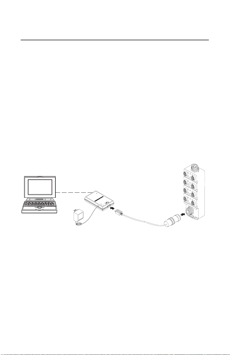
Set the Node Address
Each ArmorBlock-LP comes with its internal program set for node
address 63 and a communication rate of 125K bps. To set the node
address and communication rate, you need the following:
• host computer with DeviceNet Manager Software (or similar
configuration software tool)
• 1770-KFD RS-232 module (or similar interface)
• suitable cables to connect the 1770-KFD to your module and to
connect the 1770-KFD to your host computer
Set up a system (as shown below) to communicate with your
ArmorBlock module to set the node address and communication rate to
meet your system requirements.
Power from 9V dc power supply adapter
1770-KFD
RS-232 module
Host computer with
DeviceNetManager
software
Power Supply
Open style connector
to sealed mini–connector
Mount the ArmorBlock Module
Mount the block module directly to the machine or device. Complete
mounting dimensions are shown below.
Publication
1792-5.8 – December 1997
30195–
Page 4

ArmorBlock-LP 8 Input/8 Output Module4
Mounting Dimensions
1.8
1.5
(45)
(38)
0.63
(16)
0.8
(20.1)
4.2
(107)
2.4
(60)
inches
(millimeters
1.4
(36)
8
B
A
B
A
7
(27)
6
B
A
B
A
5
1.1
1.1
(27)
6.8
B
A
B
A
34
1.1
(27)
6.0
(152)
2
B
A
B
A
1
1.25
(32)
1.0
(25.5)
1.3
(33)
(172.1)
Use 3 #8 (4mm) screws to mount block
Connect the Wiring to the ArmorBlock Module
This module uses quick disconnect, screw-on style connectors for:
• I/O input/output wiring
• the DeviceNet connector
• the output power connector
Four
5-pin Output Micro-connectors (2, 4, 6, and 8)
2.0
(51)
0.18
(4.5)
1.5
(39)
30199–M
Output Power
3-pin Mini-connector
Publication
1792-5.8 – December 1997
8
OUTIN
B
A
B
A
7
6
B
A
B
A
5
B
A
B
A
34
A
A
5-pin DeviceNet Mini-connector
Four 5-pin Input Micro-connectors (1, 3, 5 and 7)
2
B
B
1
30197–M
Page 5

ArmorBlock-LP 8 Input/8 Output Module 5
I/O
I
or
I/O
or
Seven micro caps are included with your module. Use these caps to
cover and seal unused ports. Pinout diagrams for the connectors are
shown below.
ATTENTION: Make sure all connectors are securely
tightened to properly seal the connections against leaks and
!
maintain IP67 requirements.
Connecting the Input Wiring
Connect input wiring to the micro-connectors which screw into mating
connectors on the front of the block.
nput Micro-Connect
34
5
2
(V
iew into socket)
Pin 1 = Sensor Source V
Pin 2 = Signal B
1
Pin 3 = Negative/Return
Pin 4 = Signal A
Pin 5 = Ground
oltage Positive
Connecting the Output Wiring
Connect output wiring to the micro-connectors which screw into mating
connectors on the front of the block.
Output Micro-Connect
Pin 1 = No connection
34
5
2
(V
iew into socket)
1
Pin 2 = Signal B
Pin 3 = Negative/Return
Pin 4 = Signal A
Pin 5 = Ground
Publication
1792-5.8 – December 1997
Page 6

ArmorBlock-LP 8 Input/8 Output Module6
Outpu
or
or
Connecting the Output Power Wiring
Connect output power wiring to the 3-pin mini-connector on the end of
the block.
Important:
The outputs use electronic overcurrent fault protection. Make certain
your output power supply can handle overcurrent events.
t Power Mini-Connect
3
1
(View into pins)
2
Pin 1 = Chassis ground
Pin 2 = +24V dc
Pin 3 = Negative/Return
Connecting the DeviceNet Wiring
Connect DeviceNet wiring to the 5-pin mini-connector on the end of the
block. Connections are shown below.
DeviceNet Mini-Connect
3
4
5
(View into pins)
2
1
Pin 1 = Drain (Bare)
Pin 2 = V+ (Red)
Pin 3 = V– (Black)
Pin 4 = CAN–HI (White)
Pin 5 CAN–LO (Blue)
Note: Colors are
DeviceNet standard
Communicate with Your ArmorBlock Module
This ArmorBlock module’s I/O is exchanged with the master through a
poll, bit strobe or change of state connection.
When set for Polled, Bit Strobe, or change of state, the module consumes
and produces as follows:
Publication
1792-5.8 – December 1997
Page 7

ArmorBlock-LP 8 Input/8 Output Module 7
Type of I/O Connections Consumes Produces
Polled 1 Bytes 2 Bytes
Bit Strobe
Change of State
0 Bytes 2 Bytes
0 Bytes 2 Bytes
Polled device – a master initiates communication by sending its polled
I/O message to the ArmorBlock module. The 8 input/8 output module
consumes the message, updates outputs, and produces a response that
reflects the status of 1) its inputs, and 2) any input or output faults.
Change of state device – productions occur when an input or fault
condition changes. If neither has occurred within the “expected packet
rate,” a heartbeat production occurs. This heartbeat production tells the
scanner module that the ArmorBlock module is alive and ready to
communicate.
Bit Strobe device – a master initiates communication by sending its bit
strobe I/O message. All bit strobed devices then respond. The 8 input/8
output module consumes the message, and produces a response that
reflects the status of inputs and outputs.
Refer to the table below for the word/bit definitions.
Bit 07 06 05 04 03 02 01 00
Produces I7B I5B I3B I1B I7A I5A I3A I1A
Produces IS OF Reserved
Consumes O8B O6B O4B O2B O8A O6A O4A O2A
Where: I = Input
O = Output
IS = Sensor source voltage fault
OF = Output fault status
Publication
1792-5.8 – December 1997
Page 8

ArmorBlock-LP 8 Input/8 Output Module8
Produces
Word Bit Description
Produces 00–07 Input Status bits – when the bit is set (1), the input is on. Bit 00
Produces
Consumes 00–07 Output bits – when the bit is set (1), the output is on. Bit 00
corresponds to input 1A, bit 01 corresponds to input 3A, bit 02 to
input 5A, bit 03 input 7A. Bit 04 corresponds to input 1B, bit 05 to
input 3B, bit 06 to input 5B, and bit 07 to input 7B.
00–05 Reserved
06 OF = output fault status bit – indicates presence of field power
(default). Can also indicate no load or overload condition when
diagnostics are enabled. Refer to publication 1792-2.1, ArmorBlock
and AmorBlock-LP Product Data.
07 IS = Sensor source voltage fault bit – this bit is set (1) when the
sensor source voltage is faulted.
corresponds to output 2A, bit 01 corresponds to output 4A, bit 02 to
output 6A, bit 03 output 8A. Bit 04 corresponds to output 2B, bit 05
to output 4B, bit 06 to output 6B, and bit 07 to output 8B.
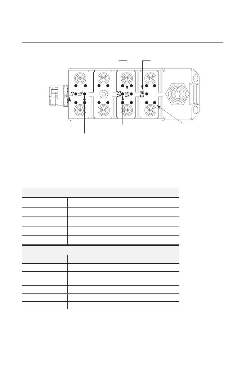
Troubleshoot with the Indicators
The ArmorBlock I/O module has the following indicators:
• Network status indicators (NS)
• Module status indicator (MS)
• Individual I/O status indicators A and B
• Power Status indicators
– module power
– output voltage
– sensor and output status
Publication
1792-5.8 – December 1997
Page 9
ArmorBlock-LP 8 Input/8 Output Module 9
NS = Network Status Indicator
Output
Connector
= Output Power
U
S
Supply Status Indicator
8
OUTIN
B
A
A
A
B
A
7
U
= Module Power Supply
L
6
B
B
5
B
A
B
A
34
MS = Module Status
Indicator
OVL = Sensor and Output
Status Indicator
2
B
A
B
A
1
A and B = Input
and Output I/O
Status Indicators
Status Indicator
Note: This
module contains a circuit to protect the DeviceNet power supply from short
circuits in an attached sensor or sensor cable. If you connect a sensor while the
module is powered, the surge current produced by the sensor can cause the
module to fault. This operation is normal.
Network Status Indicator NS
Indication Status
Flashing Green On-line, not connected
Solid Green Link OK, on-line connected
Flashing Red At least 1 I/O connection is in the timed-out state
Solid Red Incorrect baud rate, or a duplicate Mac ID exists
Module
Status Indicator MS
Indication Status
OFF
Flashing
Green/OFF
Solid Green On-line, link okay, connected
Flashing Red Recoverable fault
Solid Red Critical failure
No power, or no network access
On-line but not connected
30197–M
Publication
1792-5.8 – December 1997
Page 10

ArmorBlock-LP 8 Input/8 Output Module10
Sensor
Short Circuit Indicator OVL
Indication Status
OFF Sensor source voltage operating correctly
Solid Red 1 or more Sensor source voltage shorts, output
Output
I/O Status Indicators A and B
overload or no load condition
Indication Status
OFF Output is off
Yellow Output is on
Input
I/O Status Indicators A and B
Indication Status
OFF No valid input signal present
Yellow Valid input signal present
Module
and Sensor Power Supply Status Indicators US and U
Indication Status
OFF Power supply is not functioning correctly
Green Power Supply is operating
Specifications
L
8
Input/8 Output Module – Cat. No. 1792-IB8XOB8PLP
Input Specifications
Inputs per Block 8 sinking inputs labeled 1, 3, 5, and 7
On-state Voltage Range 12–30V dc
On-state Current Maximum
Minimum
Off-state Voltage Maximum 5V dc
Off-state Current Minimum 0.8mA
Transition Voltage 5–12.0V dc
Transition Current 0.8–2.2mA
Input Signal Delay
Off to On or On to Off 1ms maximum
Specifications continued on next page.
Publication
1792-5.8 – December 1997
15.0mA @ 30V dc
1.6mA @ 12V dc
Page 11

ArmorBlock-LP 8 Input/8 Output Module 11
Sensor Source Voltage
Current
Output
Specifications
Output Power Supply
Outputs per Block 8 Sourcing Outputs – labeled 2, 4, 6 and 8
Output Voltage Range 19–30V dc
On-state Current Maximum 1.0A per output
On-state Voltage Maximum 3V dc at rated current
Module Current (all outputs on) 8.0A per module
Off-state Leakage Current 1.5mA maximum per output
Specifications continued on next page.
General
Indicators Network Status – red/green
Communication Rate in Baud 125k, 250k, 500k software selectable
DeviceNet Power Voltage
Specifications continued on next page.
Specifications
Current
Minimum 13V dc @ 400mA out and
DeviceNet power = 15V dc
50mA per point, 0.4A total per module
Note: In order to comply with CE Low Voltage Directives,
you must use a Safety Extra Low Voltage (SELV) or a
Protected Extra Low Voltage (PELV) power supply to
power the outputs of this module.
Module Status – red/green
Sensor Supply Status – green
Module Power Supply Status – green
Short Circuit Sensor – red
I/O Status – yellow
11.0 – 25.0V dc
100mA (no powered sensors); 500mA (full sensor load)
Publication
1792-5.8 – December 1997
Page 12

ArmorBlock-LP 8 Input/8 Output Module12
General
Dimensions Inches
Specifications
Millimeters
6.8H X 2.4W X 2.0D
172.1H X 60W X 51D
Environmental Conditions
Operational Temperature
Storage Temperature
Relative Humidity
ShockOperating
Non-operating
Vibration
0 to 60oC (32 to 140oF)
–20 to 80oC (–40 to 176oF)
up to 100%
30 g peak acceleration, 11(+
50 g peak acceleration, 11(+
1)ms pulse width
1)ms pulse width
Tested 10 g @ 10–500Hz per IEC 68-2-6
Conductors Refer to publication 1485-6.7.1 for information on cabling
for your DeviceNet module.
Enclosure Meets or exceeds IP67
Agency Certification CE marked for all applicable directives
Product Data (user information) Publication 1792-2.1
This product has been tested at an Open DeviceNet Vendor
Association, Inc. (ODVA) authorized independent test laboratory
and found to comply with ODVA Conformance Test Software
Version FT 1.3/1.1.
Worldwide representation.
Argentina •
Colombia • Costa Rica • Croatia • Cyprus • Czech Republic • Denmark • Ecuador • Egypt • El Salvador
Finland •
Indonesia •
Mexico •
Puerto Rico • Qatar • Romania • Russia–CIS • Saudi Arabia • Singapore
Africa, Republic • Spain • Sweden
United Kingdom • United States • Uruguay • V
Allen-Bradley Headquarters, 1201 South Second Street, Milwaukee, WI 53204 USA, Tel: (1)
414 382-2000 Fax: (1) 414 382-4444
Publication
Publication
Supersedes
Australia • Austria • Bahrain • Belgium
France • Germany • Greece • Guatemala • Honduras • Hong Kong • Hungary • Iceland • India
Ireland • Israel • Italy • Jamaica •
Netherlands
1792-5.8 – December 1997
1792-5.8 – December 1997
publication 1792-5.8 – September 1997
• New
Zealand • Norway
• Switzerland • T
• Brazil •
Bulgaria • Canada • Chile • China, PRC
Japan • Jordan • Korea • Kuwait • Lebanon
• Pakistan •
enezuela • Y
Peru
• Philippines •
aiwan
• Thailand • T
ugoslavia
Copyright 1997 Allen-Bradley Company
Poland • Portugal
• Slovakia • Slovenia •
urkey • United Arab Emirates
• Malaysia •
•
South
PN955128–90
, Inc. Printed in USA
•
•
•
•
 Loading...