

Page 1
Installation Instructions
High Current 8 Input/8 Output
ArmorBlock I/O Module Series B
(Cat. No. 1792D-88HC)
41945
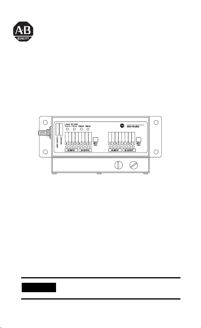
The High Current ArmorBlock™ I/O module (Cat. No. 1792D-88HC)
is a stand-alone 24V dc I/O product which communicates via a
DeviceNet™ network. The semi-sealed housing requires no
enclosure.
This module has 8 inputs and 8 outputs. Inputs are 24V dc PNP
(sourcing) or NPN (sinking) devices. Outputs are self-protected 24V
dc and are for sourcing only. Diagnostic features included are output
short circuit and open wire detection reported to the point level.
Check Your Package Contents
Your package contains:
• 1 High Current Module
• Installation Instructions
IMPORTANT
Mating connectors and/or cable assembly must be
ordered separately.
Publication 1792D-IN005D-EN-P - February 2002
Page 2

2 High Current 8 Input/8 Output ArmorBlock I/O Module Series B
ATTENTION
!
Important User Information
Because of the variety of uses for the products described in this
publication, those responsible for the application and use of these
products must satisfy themselves that all necessary steps have been
taken to assure that each application and use meets all performance
and safety requirements, including any applicable laws, regulations,
codes and standards. In no event will Allen-Bradley be responsible or
liable for indirect or consequential damage resulting from the use or
application of these products.
Any illustrations, charts, sample programs, and layout examples
shown in this publication are intended solely for purposes of
example. Since there are many variables and requirements associated
with any particular installation, Allen-Bradley does not assume
responsibility or liability (to include intellectual property liability) for
actual use based upon the examples shown in this publication.
Allen-Bradley publication SGI-1.1, Safety Guidelines for the
Application, Installation and Maintenance of Solid-State Control
(available from your local Allen-Bradley office), describes some
important differences between solid-state equipment and
electromechanical devices that should be taken into consideration
when applying products such as those described in this publication.
Reproduction of the contents of this copyrighted publication, in
whole or part, without written permission of Rockwell Automation, is
prohibited.
Throughout this publication, notes may be used to make you aware
of safety considerations. The following annotations and their
accompanying statements help you to identify a potential hazard,
avoid a potential hazard, and recognize the consequences of a
potential hazard:
Publication 1792D-IN005D-EN-P - February 2002
Identifies information about practices or
circumstances that can lead to personal injury or
death, property damage, or economic loss.
Page 3

High Current 8 Input/8 Output ArmorBlock I/O Module Series B 3
ATTENTION
!
IMPORTANT
Identifies information that is critical for
successful application and understanding of the
product.
Environment and Enclosure
This equipment is intended for use in a Pollution
Degree 2 industrial environment, in overvoltage
Category II applications (as defined in IEC
publication 60664-1), at altitudes up to 2000
meters without derating.
This equipment is considered Group 1, Class A
industrial equipment according to IEC/CISPR
Publication 11. Without appropriate precautions,
there may be potential difficulties ensuring
electromagnetic compatibility in other
environments due to conducted as well as
radiated disturbance.
This equipment is supplied as "enclosed"
equipment. It should not require additional
system enclosure when used in locations
consistent with the enclosure type ratings stated
in the Specifications section of this publication.
Subsequent sections of this publication may
contain additional information regarding specific
enclosure type ratings, beyond what this product
provides, that are required to comply with
certain product safety certifications.
See NEMA Standards publication 250 and IEC
publication 60529, as applicable, for
explanations of the degrees of protection
provided by different types of enclosure. Also,
see the appropriate sections in this publication,
as well as the Allen-Bradley publication 1770-4.1
("Industrial Automation Wiring and Grounding
Guidelines"), for additional installation
requirements pertaining to this equipment.
Publication 1792D-IN005D-EN-P - February 2002
Page 4

4 High Current 8 Input/8 Output ArmorBlock I/O Module Series B
ATTENTION
!
Install Your High Current I/O Module
To install the module you must:
• Set the node address
• Mount the module
• Connect the cable assembly to the module
• Connect the DeviceNet cable to the module
• Communicate with your ArmorBlock I/O module
More detailed information about each of these steps is in the
following procedures.
Preventing Electrostatic Discharge
This equipment is sensitive to electrostatic
discharge, which can cause internal damage and
affect normal operation. Follow these guidelines
when you handle this equipment:
• Touch a grounded object to discharge
potential static.
• Wear an approved grounding wriststrap.
• Do not touch connectors or pins on
component boards.
• Do not touch circuit components inside the
equipment.
• If available, use a static-safe workstation.
• When not in use, store the equipment in
appropriate static-safe packaging.
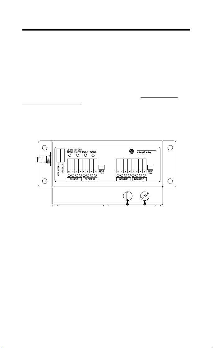
Set the Node Address
Valid node addresses are 00 to 63.
Set the node address using the rotary switches, RSNetWorx for
DeviceNet™, DeviceNetManager™, or another software configuration
tool. Setting the switches between 64 and 99 lets the software have
address control.
Each module is shipped with the node address set to 63 in the
module’s memory. The rotary switches are set for position 99 at
shipment. The switches are located on the bottom of the module.
Publication 1792D-IN005D-EN-P - February 2002
Page 5
High Current 8 Input/8 Output ArmorBlock I/O Module Series B 5
The two switches are:
• MSD (most significant digit)
• LSD (least significant digit)
To reset the node address, use a small blade screwdriver to rotate the
switches. Line up the small arrow on the switch with the number
setting you wish to use.
The rotary switches are read at module power up only. Settings
between 64 and 99 cause the module to use the last valid node
address stored internally. Example: The last setting was 40. If a
change is made to 68, and then you power up, the address will
default to 40. Use the mini caps to cover and seal node address
switch ports.
Refer to the illustration of the rotary switches below.
41945
MSD
LSD
The module is equipped with AutoBaud detect. AutoBaud lets the
module read the settings already in use on your DeviceNet network
and automatically adjusts to follow those settings. The module is
shipped with AutoBaud enabled.
Mount the Module
1. Place the module against the panel where you want it
mounted.
2. Drill holes in the panel that are aligned with the moving holes
on the module.
Publication 1792D-IN005D-EN-P - February 2002
Page 6

6 High Current 8 Input/8 Output ArmorBlock I/O Module Series B
3. Place screws through each of the 4 mounting holes and
tighten the screws until the module is firmly in place.
7.74in.
196.6mm
3.06in.
77.6mm
Side View
Front View
41945
2.63in.
66.7mm
42288
Connect the Cable Assembly to the Module
Inputs, outputs, and power can either be wired directly to a mating
connector, or through a cable assembly.
Connection Using a Connector Assembly
Use the Allen-Bradley user-fabricated connector assembly, catalog
number 1792D-88HCCON, with a hand crimp tool and follow the
instructions to crimp connector contacts onto field wires. (Purchase
the hand crimp tool from Positronic Industries, Inc., part number
9501 and 9502-1). See the connector pinouts on the next page.
ATTENTION
For maximum noise immunity, input cable return
wires must be properly terminated. When inputs
are connected in loopback, return wires should
be connected together.
!
Publication 1792D-IN005D-EN-P - February 2002
Page 7

High Current 8 Input/8 Output ArmorBlock I/O Module Series B 7
Connection Using a Prefabricated Harness Assembly
1. Connect the harness assembly, 1792D-88HCCBL, to field
wiring.
2. Connect the harness connector to the module.
The 1792D-88HC module connector pinout is shown below
(looking into the module connector).
1 2 3 4 5 6 7 8 9 10
11 12 13 14 15 16 17 18 19 20
21 22 23 24 25 26 27 28 29 30
Module Connector
The mating connector pinout is shown below (looking into the
mating connector).
10 9 8 7 6 5 4 3 2 1
20 19 18 17 16 15 14 13 12 11
30 29 28 27 26 25 24 23 22 21
42285
Mating/Harness Connector
Publication 1792D-IN005D-EN-P - February 2002
42323
Page 8

8 High Current 8 Input/8 Output ArmorBlock I/O Module Series B
The following table lists the signal for each pin number.
Pin Number Signal
1PWR1+
2 IN_0 (GRP 1)
3 IN_1 (GRP 1)
4 IN_2 (GRP 1)
5 IN_3 (GRP 1)
6 IN_0 (GRP 2)
7 IN_1 (GRP 2)
8 IN_2 (GRP 2)
9 IN_3 (GRP 2)
10 PWR2+
11 PWR1+
12 PWR1-
13 PWR1-
14 PWR1-
15 PWR1-
16 PWR2-
17 PWR2-
18 PWR2-
19 PWR2-
20 PWR2+
21 PWR1+
22 OUT_0 (GRP 1)
23 OUT_1 (GRP 1)
24 OUT_2 (GRP 1)
25 OUT_3 (GRP 1)
26 OUT_0 (GRP 2)
27 OUT_1 (GRP 2)
28 OUT_2 (GRP 2)
29 OUT_3 (GRP 2)
30 PWR2+
Publication 1792D-IN005D-EN-P - February 2002
Page 9

High Current 8 Input/8 Output ArmorBlock I/O Module Series B 9
Connect the DeviceNet Cable to the Module
Connect the DeviceNet wiring to the 5-pin micro-connector on the
module. The micro-connector pinout is shown below.
2
5
3
4
Looking into connector pins
IMPORTANT
Pin 1 Drain
(not connected internally)
Pin 2 V+
1
Pin 3 VPin 4 CAN_H
Pin 5 CAN_L
42286
If the devices (sensors) connected to the input
connections require Class 2 power to operate, the
DeviceNet connections of this equipment must be
powered by a Class 2 source.
Communicate with Your ArmorBlock I/O Module
This High Current module’s I/O is exchanged with the master
through a polled, cyclic, or change-of-state connection.
The module produces and consumes I/O data as follows:
Type of I/O Connections Consumes Produces
Polled 1 Byte 3 Bytes
Cyclic 1 Byte 3 Bytes
Change-of-State 1 Byte 3 Bytes
Polled - master initiates communication by sending its polled I/O
message to the module. The module consumes the message, updates
any outputs, and produces a response. If inputs are present, the
response contains the input data.
Cyclic - allows configuration of the block as an I/O client. The block
will produce and consume its I/O cyclically at the rate configured.
Publication 1792D-IN005D-EN-P - February 2002
Page 10

10 High Current 8 Input/8 Output ArmorBlock I/O Module Series B
Change-of-State - productions occur when an input changes or a
fault condition occurs. If no input or fault condition change occurs
within the expected packet rate, a heartbeat production occurs. This
heartbeat production tells the scanner module that the I/O module is
alive and ready to communicate. Consumption occurs when data
changes and the master produces new input data to the I/O block.
Refer to the table below for the word/bit definitions.
Bit 0706050403020100
Produces 0 OL7 OL6 0L5 0L4 0L3 0L2 0L1 0L0
Produces 1 NL7 NL6 NL5 NL4 NL3 NL2 NL1 NL0
Produces 2 I7 I6 I5 I4 I3 I2 I1 I0
Consumes 0 O7 O6 O5 O4 O3 O2 O1 O0
Where: OL=Output Overload NL=Output No Load I=Input O = Output
Refer to the table below for byte/bit descriptions.
Byte Bit Description
Produces 0 00-07 Output overload status
Produces 1 00-07 Output no load status
Produces 2 00-07 Input point status
Consumes 0 00-07 Output bits: When the bit is set (1), the output will
be turned on. Bit 00=output 00, bit 01=output 01,
bit 02=output 02, bit 03=output 03, bit 04=output
04, bit 05=output 05, bit 06=output 06, bit
07=output 07.
The DeviceNet Network uses advanced network technology,
producer/consumer communication, to increase network
functionality and throughput. Visit our web site at
http://www.ab.com/networks
for producer/consumer technology
information and updates.
Publication 1792D-IN005D-EN-P - February 2002
Page 11

High Current 8 Input/8 Output ArmorBlock I/O Module Series B 11
Troubleshoot with the Indicators
This module has the following indicators:
• Network/Module status indicator
• Logic status indicators
• Individual point status indicators
The following illustration shows status indicators.
Status Indicators
42287
The following table describes the network and module status
indicator.
Net/Mod Status Indicator
Indication Status
Off No power or auto bauding
Flashing Green/Off On line but not connected
Solid Green On line, link OK, connected
Flashing Red Recoverable fault-expansion module fault or module
Solid Red Unrecoverable fault
Green to Red to Off At powerup only - LED test
configuration error
I/O connection fault-one or more I/O connections in
the timed-out state
Communication failure-duplicate node address present
or incorrect baud rate
Publication 1792D-IN005D-EN-P - February 2002
Page 12

12 High Current 8 Input/8 Output ArmorBlock I/O Module Series B
The following table describes the logic status indicator.
Logic Status Indicators
State Status
Off Logic is disabled
Solid Green Logic is enabled
Flashing Green Local forces are applied and local logic is enabled
The following table describes the I/O status indicator.
I/O Status Indicators
Function LED
Auxiliary
Power
Group #1
Auxiliary
Power
Group #2
Outputs Green/
Inputs Yellow No valid input
Condition Module Illumination
Color
Yellow No auxiliary power
Auxiliary power present
Yellow No auxiliary power
Auxiliary power present
Output not energized
red
Output energized
Output shorted and latched off
Output No-load in OFF state
Val i d input
None
Yellow
None
Yellow
None
Green
Red, MS blink red
Blinking Red, MS blink Red
None
Yellow
For more information on indications, see the Technical Data,
publication 1792-TD001.
Publication 1792D-IN005D-EN-P - February 2002
Page 13

High Current 8 Input/8 Output ArmorBlock I/O Module Series B 13
Specifications
8 Input / 8 Output Module - Cat. No. 1792D-88HC
Input Specifications Max. Min.
Inputs per block 8, Configurable as sinking or sourcing in two groups of 4
Off-State Voltage 4 0
On-State Voltage 30 8
Off-State Current - 1.2mA
On-State Current 11mA (@30V dc) 2mA (@10V dc)
Output Specifications Max. Min.
Outputs per block 8 sourcing type in two groups of 4
Off Peak Blocking Voltage - 30V
On-State Voltage Drop 5Amp
On-State Current 5 Amp
Off-State Leakage 5 Amp
Module Current (all outputs) 40A -
Surge Current - for 10mS 5 Amp
repeatable every 2 sec. 10 Amp
General Specifications Max. Min.
DeviceNet Power: Voltage
Auxiliary Power Voltage
Group 1 and Group 2 Current
Indicators Net/Mod Status-red/green Auxiliary Power-yellow
Communication Rate
Dimensions (assembled to base)
inches - (millimeters)
10 Amp
10 Amp
10 Amp
Current
sourcing type is default
1V
1V
5A
10A
250uA
250uA
10A
20A
25V dc
75mA
30V dc
40A
Logic Status-green Input Point LED-yellow
Output Point LED-red/green
125Kbps @ 500 meters (1600 feet) for thick cable,
•
flat media length 375 meters
250Kbps @ 200 meters (600 feet) for thick cable, flat
•
media length 150 meters
500Kbps @ 100 meters (300 feet) for thick cable, flat
•
media length 75 meters
2.63H x 7.74W x 3.06D
(66.7H x 196.6W x 77.60D)
-
-
-
-
-
-
-
-
11V dc
125mA
8V dc (inputs)
10V dc (outputs)
40A
Publication 1792D-IN005D-EN-P - February 2002
Page 14

14 High Current 8 Input/8 Output ArmorBlock I/O Module Series B
General Specifications
Operational Temperature IEC 60068-2-1 (Test Ad, Operating Cold),
Storage Temperature IEC 60068-2-1 (Test Ab, Un-packaged Non-operating Cold),
Wiring Category
DeviceNet Conductors
Category
Relative Humidity IEC 60068-2-30 (Test Db, Un-packaged Non-operating
Shock Operating IEC60068-2-27: Test Ea (Unpackaged shock, ES#002)
Vibration IEC60068-2-6 (Test Fc, Operating):
Emissions CISPR 11:
ESD Immunity IEC 61000-4-2:
Enclosure Type Rating Meets IP52
Radiated RF Immunity IEC 61000-4-3:
EFT/B Immunity IEC 61000-4-4:
Surge Transient Immunity ±1kV line-line(DM) and ±2kV line-earth(CM) on signal ports
Conducted RF Immunity IEC 61000-4-6:
IEC 60068-2-2 (Test Bd, Operating Dry Heat),
IEC 60068-2-14 (Test Nb, Operating Thermal Shock):
–20 to 60°C (–4 to 140°F)
IEC 60068-2-2 (Test Bb, Un-packaged Non-operating Dry
Heat),
IEC 60068-2-14 (Test Na, Un-packaged Non-operating
Thermal Shock):
–40 to 85°C (–40 to 185°F)
Use 14-22 AWG wire with insulation
Temperature rating of 75°C min.
See Publication DN-6.7.2
1, 2
2
Damp Heat):
5 to 95% non-condensing
Operating 30g
Non-operating 50g
10g @ 10-500Hz
Group 1, Class A
4kV contact discharges
8kV air discharges
10V/m with 1kHz sine-wave 80%AM from 30MHz to
1000MHz
10V/m with 200Hz 50% Pulse 100%AM at 900Mhz
±2kV at 5kHz on signal ports
2kV line-earth (CM) on shielded ports
+
10Vrms with 1kHz sine-wave 80%AM from 150kHz to
80MHz
Publication 1792D-IN005D-EN-P - February 2002
Page 15

High Current 8 Input/8 Output ArmorBlock I/O Module Series B 15
General Specifications
Agency Certification
(when product is marked)
Technical Data (user information) Publication 1792-TD001
1. You use this conductor category information for planning conductor routing as described in the
system level installation manual.
2. See publication 1770-4.1, “Programmable Controller Wiring and Grounding Guidelines.”
3. See the Product Certification link at www.ab.com for Declarations of Conformity, Certificates, and
other certification details.
c-UR-us UL Recognized Component Industrial Control
Equipment, certified for US and Canada
3
European Union 89/336/EEC EMC Directive,
CE
compliant with:
EN 50081-2; Industrial Emissions
EN 50082-2; Industrial Immunity
EN 61326; Meas./Control/Lab., Industrial
Requirements
EN 61000-6-2; Industrial Immunity
3
Australian Radiocommunications Act, compliant
C-Tick
with:
AS/NZS 2064; Industrial Emissions
ODVA ODVA conformance tested to ODVA DeviceNet
specifications
This product has been tested at an Open DeviceNet Vendor
Association, Inc. (ODVA) authorized independent test laboratory and
found to comply with ODVA Conformance Test. Please contact the
ODVA website (http://www.odva.org) for listing of products tested by
ODVA independent test labs for further details.
Publication 1792D-IN005D-EN-P - February 2002
Page 16

ArmorBlock and DeviceNetManager are trademarks of Rockwell Automation.
RSNetWorx for DeviceNet is a trademark of Rockwell Software Inc.
DeviceNetManager is a trademark of Rockwell Automation Allen-Bradley Inc.
DeviceNet is a trademark of Open DeviceNet Vendor Association (ODVA).
Publication 1792D-IN005D-EN-P - February 2002 PN 957678-04
Supersedes Publication 1792D-IN005C-EN-P - February 2001 Copyright © 2002 Rockwell Automation. All rights reserved. Printed in the U.S.A.
 Loading...