

Installation Instructions
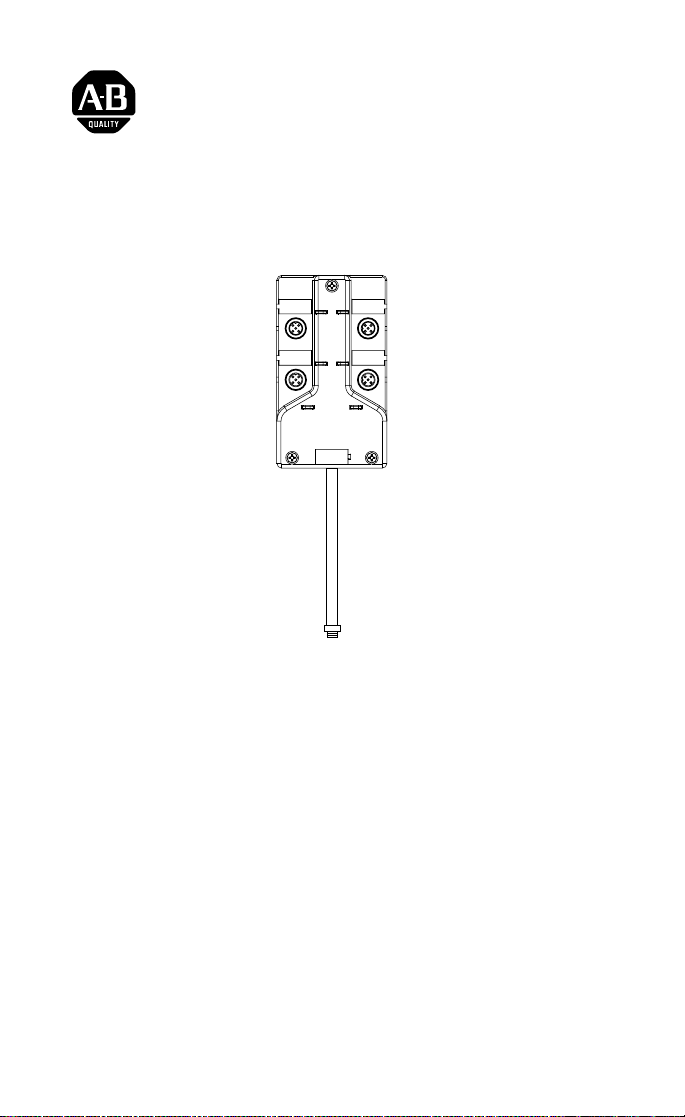
ArmorBlock LP2 4 Sinking Input Module
(Cat. No. 1792D-4B0LP)
I0
I3
I1
I2
Network Status
Module Status
41621
This ArmorBlock LP2 I/O module (Cat. No. 1792D-4B0LP) is a standalone 24V dc I/O product which communicates via a DeviceNet network.
The sealed housing of this module requires no enclosure.
This model has 4 sinking inputs.
Package Contents
Your package contains:
• 1 ArmorBlock LP2 Module
• Installation Instructions
.
Publication 1792D-5.27- January 1999

2 ArmorBlock LP2 4 Sinking Input Module
European Union Directive Compliance
If this product has the CE mark it is approved for installation within the
European Union and EEA regions. It has been designed and tested to meet
the following directives.
EMC Directive
This product is tested to meet Council Directive 89/336/EEC
Electromagnetic Compatibility (EMC) and the followin g stand ards, in
whole or in part, documented in a technical construction file:
• EN 50081-2 EMC - Generic Emission Standard, Part 2 - Industrial
Environment
• EN 50082-2 EMC - Generic Immunity Standard, Part 2 - Industrial
Environment
This product is intended for use in an industrial environme nt.
Low Voltage Directive
This product is tested to meet Council Directive 73/23/EEC Low Voltage,
by applying the safety requirements of EN 61131-2 Programmable
Controllers, Part 2 - Equipment Requirements and Tests.
For specific information required by EN 61131-2, see the appropriate
sections in this publication, as well as the following Allen-Bradley
publications:
• Industrial Automation Wiring and Grounding Guidelines For Noise
Immunity, publication 1770-4.1
• Automation Syst em s Cata lo g, pu blication B1 11
Install Your ArmorBlock LP2 I/O Module
T o install the mo du le:
• Set the node address and baud rate.
• Mount the module .
• Attach the block to the DeviceNet trunk.
• Connect the cord sets.
Set the Node Address
Set the node address using RSNetworx for DeviceNet software,
DeviceNetManager software, or another software configuration tool. The
module is equipped with AutoBaud detect. AutoBaud lets the module read
the settings already in use on your DeviceNet network and automatically
adjusts to follow those settings.
Publication 1792D-5.27- January 1999
ArmorBlock LP2 4 Sinking Input Module 3
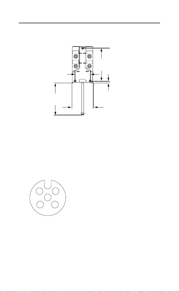
Install the Module
1. Attach the module using the dimensions shown below.
I0
I3
I2
Module Status
4.21 in
107mm
1.95 in
49.5mm
I1
Network Status
12in
305mm
0.25 in
6.25mm
1.02 in
26.0mm
2. Connect the grey DeviceNet cabl e to the DeviceNet trunk. Use the
1485P-P1R5-MN5R1 T-Part tap to make the connection to round
media. Use the 1485P-P1E4-R5 to connect to the Kwik Link flat media
system.
Connect the Input Cord Sets to the LP2 Module
This module uses 5 pin micro (12mm) style PCB mounted connectors.
Four micro caps cover the connectors on your module. Remove the caps
and connect your ca bles to the approp ria te ports.
Use the micro caps to cover and seal un used ports. A Pinout diagram for
the connector is show n next.
Input Micro-Connector
1
2
5
3
4
1
Logic Ground is approximately 0.4V above De viceNet V-measured at the module.
(View into Sockets)
Pin 1 Sensor Source Voltage
Pin 2 Not Used
Pin 3 Return Logic Ground
Pin 4 Input A
Pin 5 Not Used
1
Publication 1792D-5.27- January 1999
 Loading...