

Page 1
Installation Instructions
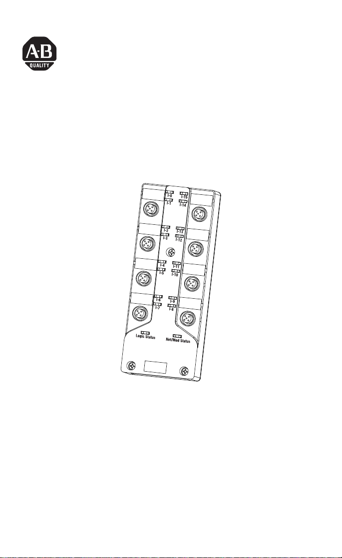
ArmorBlock MaXum 16 Input Module with
Complete Diagnostics
(Cat. No. 1792D-16BVT0CD)
30723-M
This ArmorBlock MaXum I/O module (Cat. No. 1792D-16BVT0CD)
is a stand-alone 24V dc I/O product which communicates via a
DeviceNet network. The sealed housing of this module requires no
enclosure.
This model has 16 inputs accessed through Y splitter cables. Inputs
are 24V dc and are software selectable for PNP (sourcing) or NPN
(sinking) devices. The default is sinking. Diagnostic features included
are short circuit and open wire detection reported to the point level.
This product also supports DeviceLogix.
Publication 1792D-IN053A-EN-P - August 2002
Page 2

2 ArmorBlock MaXum 16 Input Module with Complete Diagnostics
Important User Information
Because of the variety of uses for the products described in this
publication, those responsible for the application and use of these
products must satisfy themselves that all necessary steps have been
taken to assure that each application and use meets all performance
and safety requirements, including any applicable laws, regulations,
codes and standards. In no event will Rockwell Automation be
responsible or liable for indirect or consequential damage resulting
from the use or application of these products.
Any illustrations, charts, sample programs, and layout examples
shown in this publication are intended solely for purposes of
example. Since there are many variables and requirements associated
with any particular installation, Rockwell Automation does not
assume responsibility or liability (to include intellectual property
liability) for actual use based upon the examples shown in this
publication.
Allen-Bradley publication SGI-1.1, Safety Guidelines for the
Application, Installation and Maintenance of Solid-State Control
(available from your local Rockwell Automation office), describes
some important differences between solid-state equipment and
electromechanical devices that should be taken into consideration
when applying products such as those described in this publication.
Reproduction of the contents of this copyrighted publication, in
whole or part, without written permission of Rockwell Automation, is
prohibited.
Throughout this publication, notes may be used to make you aware
of safety considerations. The following annotations and their
accompanying statements help you to identify a potential hazard,
avoid a potential hazard, and recognize the consequences of a
potential hazard:
Publication 1792D-IN053A-EN-P - August 2002
Page 3

ArmorBlock MaXum 16 Input Module with Complete Diagnostics 3
ATTENTION
!
WARNING
!
IMPORTANT
Identifies information about practices or circumstances
that can lead to personal injury or death, property damage,
or economic loss.
Identifies information about practices or circumstances
that can cause an explosion in a hazardous environment,
which may lead to personal injury or death, property
damage, or economic loss.
Identifies information that is critical for successful
application and understanding of the product.
Publication 1792D-IN053A-EN-P - August 2002
Page 4

4 ArmorBlock MaXum 16 Input Module with Complete Diagnostics
ATTENTION
!
Environment and Enclosure
This equipment is intended for use in a Pollution Degree 2
industrial environment, in overvoltage Category II
applications (as defined in IEC publication 60664-1), at
altitudes up to 2000 meters without derating.
This equipment is considered Group 1, Class A industrial
equipment according to IEC/CISPR Publication 11. Without
appropriate precautions, there may be potential
difficulties ensuring electromagnetic compatibility in other
environments due to conducted as well as radiated
disturbance.
This equipment is supplied as "enclosed" equipment. It
should not require additional system enclosure when used
in locations consistent with the enclosure type ratings
stated in the Specifications section of this publication.
Subsequent sections of this publication may contain
additional information regarding specific enclosure type
ratings, beyond what this product provides, that are
required to comply with certain product safety
certifications.
See NEMA Standards publication 250 and IEC publication
60529, as applicable, for explanations of the degrees of
protection provided by different types of enclosure. Also,
see the appropriate sections in this publication, as well as
the Allen-Bradley publication 1770-4.1 ("Industrial
Automation Wiring and Grounding Guidelines"), for
additional installation requirements pertaining to this
equipment.
Package Contents
Your package contains:
•1 ArmorBlock MaXum Module
•Installation Instructions
(Please note: Cable bases are ordered and shipped separately.)
Publication 1792D-IN053A-EN-P - August 2002
Page 5

ArmorBlock MaXum 16 Input Module with Complete Diagnostics 5
ATTENTION
!
Install Your ArmorBlock MaXum I/O Module
To install the module:
•Set the node address
•Mount the module to the cable base
•Connect the cord sets
•Communicate with the module
Preventing Electrostatic Discharge
This equipment is sensitive to electrostatic discharge, which
can cause internal damage and affect normal operation.
Follow these guidelines when you handle this equipment:
• Touch a grounded object to discharge potential static.
• Wear an approved grounding wriststrap.
• Do not touch connectors or pins on component boards.
• Do not touch circuit components inside the equipment.
• If available, use a static-safe workstation.
• When not in use, store the equipment in appropriate
static-safe packaging.
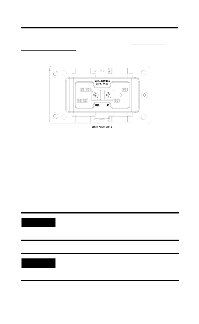
Set the Node Address
Valid node addresses are 00 to 63.
Set the node address using the rotary switches, DeviceNetManager,
RSNetWorx for DeviceNet, or other software configuration tool.
Setting the switches between 64 to 99 lets the software have address
control.
Each module is shipped set for node address 63. The switches are
located on the underside of the module. The two switches are:
•MSD (most significant digit)
•LSD (least significant digit)
To reset the node address, use a small blade screwdriver to rotate the
switches. Line up the small black dot on the switch with the number
setting you wish to use.
Publication 1792D-IN053A-EN-P - August 2002
Page 6
6 ArmorBlock MaXum 16 Input Module with Complete Diagnostics
The rotary switches are read at module power up only. Settings
between 64 and 99 cause the module to use the last valid node
address stored internally. Example: The last setting was 40. If a
change is made to 68, and then you power up, the address will
default to 40.
Example: Node address is set at 62 (see small black dots).
30703
The module is equipped with AutoBaud detect. AutoBaud lets the
module read the settings already in use on your DeviceNet network
and automatically adjusts to follow those settings.
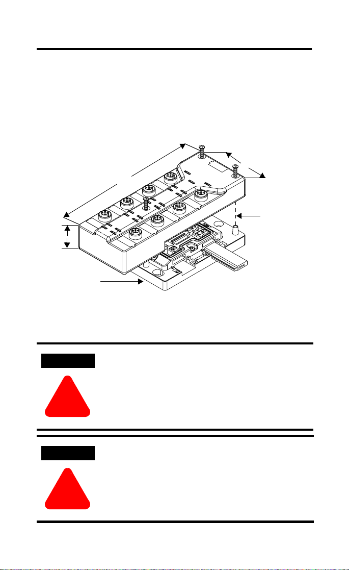
Mount the Module to the Cable Base
This module mounts to the following cable bases:
•1792D-CBFM for KwikLink™ flat media installation
•1792D-CB12 for 12mm drop cable installation
•1792D-CB18 for round media trunk connection
•or other optional cable base assembly
IMPORTANT
To mount the module to the cable base:
IMPORTANT
The cable base should already be installed. See publication
1792D-IN009 for more information on installing the cable
base.
Proper alignment of the screws is necessary to complete the
connections between the module contacts and the cable
contacts.
Publication 1792D-IN053A-EN-P - August 2002
Page 7
ArmorBlock MaXum 16 Input Module with Complete Diagnostics 7
WARNING
!
WARNING
!
1. Position the module over the mounted cable base. Align the
three captive screws in the module with the accepting
receptacles in the base.
2. Tighten the screws to secure the module to the base.
Note: Dimensions change according to the cable base and
module combination used.
2
.
7
6
(
8
.
6
)
6.85 (174mm)
Align the
screws to
properly
assemble the
1.9 (48.26)
Cable Base 1792D-CBFM is
used for this example.
Assembled
dimensions in (mm)
module to the
base.
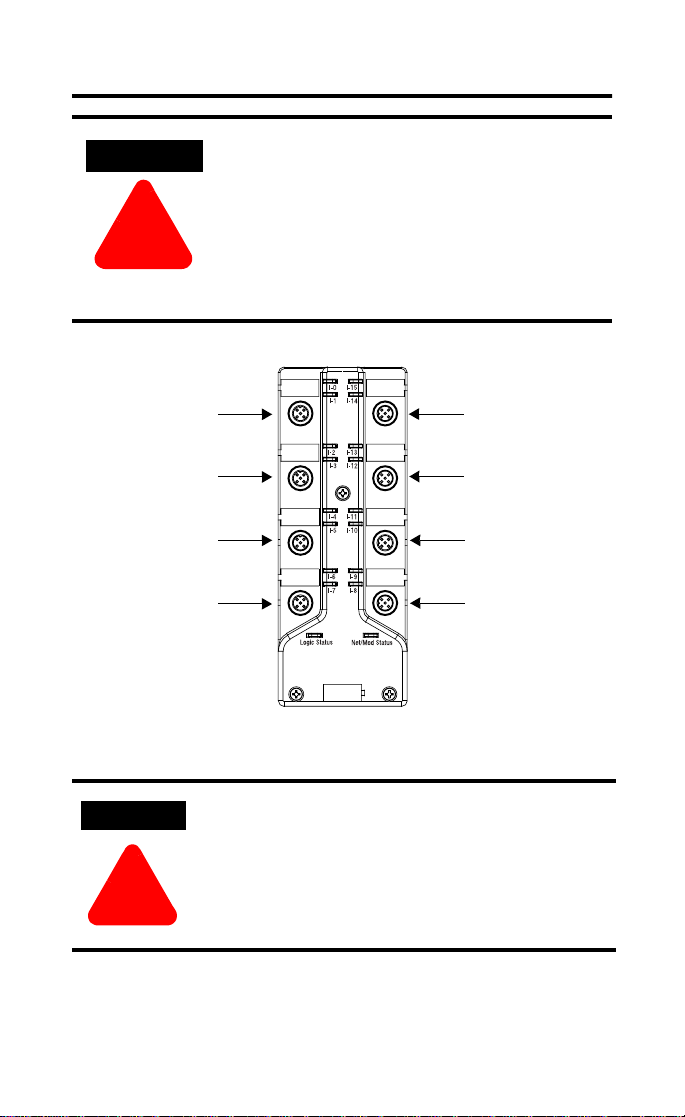
Connect the Input Cord Sets to the MaXum Module
30724-M
If you connect or disconnect wiring while the field-side
power is on, an electrical arc can occur. This can cause an
explosion in hazardous location installations. Be sure that
power is removed or the area is nonhazardous before
proceeding.
Use supply wires suitable for 30°C above surrounding
ambient.
Publication 1792D-IN053A-EN-P - August 2002
Page 8

8 ArmorBlock MaXum 16 Input Module with Complete Diagnostics
WARNING
!
This module uses 5 pole micro (12mm) style PCB mounted
connectors.
Eight micro caps cover the connectors on your module. Remove the
caps and connect your cables to the appropriate ports. This product
has two inputs per connector. Use a “Y” splitter cable for access to all
input connections.
Use the micro caps to cover and seal unused ports. A pinout diagram
for the connectors is shown next.
Input Micro-Connector
(View into Socket)
Pin 1 Sensor Source Voltage A
Pin 2 Input B
Pin 3 Return Logic Ground
Pin 4 Input A
Pin 5 Sensor Source Voltage B
1
1
Logic Ground is approximately 0.4V above DeviceNet V-measured at the module.
Use Rockwell Automation Y-cables 879D-F4ACDM5-x, where
x=length in meters (0M3, 1, 2, 3, 5, 10). Please refer to publication
C114-CA001 for other Rockwell Automation cables and cord sets
offerings.
IMPORTANT
Publication 1792D-IN053A-EN-P - August 2002
If the devices (sensors) connected to the input connections
require Class 2 power to operate, the DeviceNet connections
of this equipment must be powered by a Class 2 source.
When used in a Class I, Division 2, hazardous location, this
equipment must be mounted in a suitable enclosure with
proper wiring method that complies with the governing
electrical codes.
41452
Page 9
ArmorBlock MaXum 16 Input Module with Complete Diagnostics 9
ATTENTION
!
WARNING
!
• Make sure all connectors and caps are securely tightened
to properly seal the connections against leaks and
maintain IP67 requirements.
• For maximum noise immunity, input and output cable
return wires must be properly terminated. When inputs
and outputs are connected in loopback, return wires
should be connected together.
• I/O cable length should be less than 30 meters.
Input connectors for this module are shown below.
Connector A
Connector B
Connector C
Connector D
Input 0
Input 1
Input 2
Input 3
Input 4
Input 5
Input 6
Input 7
Input 15
Input 14
Input 13
Input 12
Input 11
Input 10
Input 9
Input 8
DeviceNet Cable
If you connect or disconnect the DeviceNet cable with
power applied to this module or any device on the network,
an electrical arc can occur. This could cause an explosion
in hazardous location installations.
Be sure that power is removed or the area is nonhazardous
before proceeding.
DeviceNet cables are described in the installation publications for the
cable base of your choice. Refer to the following publications:
Connector H
Connector G
Connector F
Connector E
30722-M
Publication 1792D-IN053A-EN-P - August 2002
Page 10

10 ArmorBlock MaXum 16 Input Module with Complete Diagnostics
•1792D-IN009 ArmorBlock MaXum Cable Base Installation Guide
•DN-6.7.2 DeviceNet Cable Planning and Installation Manual
Communicate With Your ArmorBlock MaXum Module
This ArmorBlock module’s I/O is exchanged with the master through
a polled, change-of-state, or cyclic connection.
The module consumes and produces input data as follows:
Type of I/O Connections Consumes Produces
Cyclic 0 Byte 6 Bytes
Polled 0 Byte 6 Bytes
Change-of-State 0 Byte 6 Bytes
Cyclic - allows configuration of the block as an I/O client. The block
will produce its I/O cyclically at the rate configured.
Polled - a master initiates communication by sending its polled I/O
message to the module. The 16 input module scans the inputs and
fault bits producing a response that reflects their status.
Change of State - productions occur when an input changes or a
fault condition occurs. If no input or fault condition change occurs
within the expected packet rate, a heartbeat production occurs. This
heartbeat production tells the scanner module that the module is alive
and ready to communicate.
Refer to the table below for the word/bit definitions.
Bit 0706050403020100
Produced 0 In 7In 6In 5In 4In 3In 2In 1In 0
Produced 1 In 15 In 14 In 13 In 12 In 11 In 10 In 9 In 8
Produced 2 ISC-7 ISC-6 ISC-5 ISC-4 ISC-3 ISC-2 ISC-1 ISC-0
Produced 3 ISC-15 ISC-14 ISC-13 ISC-12 ISC-11 ISC-10 ISC-9 ISC-8
Produced 4 OW-7 OW-6 OW-5 OW-4 OW-3 OW-2 OW-1 OW-0
Produced 5 OW-15 OW-14 OW-13 OW-12 OW-11 OW-10 OW-9 OW-8
Where: I = Input ISC = Input Short Circuit in Sensor Source Voltage OW = Off Wire
Note: If you are using DeviceLogix, please refer to publication no.
1792-TD001 for the alternate I/O assemblies for DeviceLogix.
Publication 1792D-IN053A-EN-P - August 2002
Page 11

ArmorBlock MaXum 16 Input Module with Complete Diagnostics 11
Byte Bit Description
Produced 0 00-07 Input status bits: When the bit is set (1), the input is on.
Produced 1 00-07 Input status bits: Bit 00 = input 8, bit 01= input 9, bit 02 = input
Produced 2 00-07 Sensor source voltage, input short circuit (ISC): Fault bits are set
Produced 3 00-07 Sensor source voltage, input short circuit (ISC): Fault bits are set
Produced 4 00-07 Off-Wire fault (OW):
Produced 5 00-07 Off-Wire fault (OW):
Where: I = Input ISC = Input Short Circuit in Sensor Source Voltage OW = Off Wire
Bit 00 = input 0, bit 01= input 1, bit 02 = input 2, bit 03 = input 3,
bit 04 = input 4, bit 05 = input 5, bit 06 = input 6, bit 07 = input 7.
10, bit 03 = input 11, bit 04 = input 12, bit 05 = input 13,
bit 06 = input 14, bit 07 = input 15.
(1) when the sensor source voltage is faulted.
Bit 00 is ISC-0 = a short circuit for input 0
Bit 01 is ISC-1 = a short circuit for input 1
Bit 02 is ISC-2 = a short circuit for input 2
Bit 03 is ISC-3 = a short circuit for input 3
Bit 04 is ISC-4 = a short circuit for input 4
Bit 05 is ISC-5 = a short circuit for input 5
Bit 06 is ISC-6 = a short circuit for input 6
Bit 07 is ISC-7 = a short circuit for input 7
(1) when the sensor source voltage is faulted.
Bit 00 is ISC-8 = a short circuit for input 8
Bit 01 is ISC-9 = a short circuit for input 9
Bit 02 is ISC-10 = a short circuit for input 10
Bit 03 is ISC-11 = a short circuit for input 11
Bit 04 is ISC-12 = a short circuit for input 12
Bit 05 is ISC-13 = a short circuit for input 13
Bit 06 is ISC-14 = a short circuit for input 14
Bit 07 is ISC-15 = a short circuit for input 15
Bit 00 is OW-0 = an off-wire fault for output 0
Bit 01 is OW-1 = an off-wire fault for output 1
Bit 02 is OW-2 = an off-wire fault for output 2
Bit 03 is OW-3 = an off-wire fault for output 3
Bit 04 is OW-4 = an off-wire fault for output 4
Bit 05 is OW-5 = an off-wire fault for output 5
Bit 06 is OW-6 = an off-wire fault for output 6
Bit 07 is OW-7 = an off-wire fault for output 7
Bit 00 is OW-8 = an off-wire fault for output 8
Bit 01 is OW-9 = an off-wire fault for output 9
Bit 02 is OW-10 = an off-wire fault for output 10
Bit 03 is OW-11 = an off-wire fault for output 11
Bit 04 is OW-12 = an off-wire fault for output 12
Bit 05 is OW-13 = an off-wire fault for output 13
Bit 06 is OW-14 = an off-wire fault for output 14
Bit 07 is OW-15 = an off-wire fault for output 15
Publication 1792D-IN053A-EN-P - August 2002
Page 12

12 ArmorBlock MaXum 16 Input Module with Complete Diagnostics
The DeviceNet Network uses advanced network technology,
producer/consumer communication, to increase network
functionality and throughput. Visit our website at
http://www.ab.com/networks
for producer/consumer technology
information and updates.
Troubleshoot with the Indicators
This module has the following indicators:
•Network and Module status indicator
•Logic status indicator
•Individual point status indicators for inputs 0 through 15
Point indicators for
inputs 0 and 1
Connector A
Point indicators for
inputs 2 and 3
Connector B
Point indicators for
inputs 4 and 5
Connector C
Point indicators for
inputs 6 and 7
Connector D
Module Status
Indicators
LED Assignments
Point indicators for
inputs 14 and 15
Connector H
Point indicators for
inputs 12 and 13
Connector G
Point indicators for
inputs 10 and 11
Connector F
Point indicators for
inputs 8 and 9
Connector E
30722-M
The following table describes network and module status indicators.
Net/Mod Status Indicator
Indicator Status
Off No power or auto bauding
Flashing Green/Off On line but not connected
Solid Green On line, link OK, connected
Flashing Red Recoverable fault - module configuration error
I/O connection fault - one or more I/O connections in the timed-out state
Publication 1792D-IN053A-EN-P - August 2002
Page 13

ArmorBlock MaXum 16 Input Module with Complete Diagnostics 13
Net/Mod Status Indicator
Indicator Status
Solid Red Unrecoverable fault
Communication failure - duplicate node address present or incorrect
baud rate
Green to Red to Off At powerup only - LED test
The following table describes logic status indicators.
Logic Status Indicators
State Status
Off Logic is disabled
Solid Green Logic is enabled
Flashing Green Local forces are applied and local logic is enabled
The following table describes individual I/O status indicators.
I/O Status Indicators
Function Module Status Indicator
Inputs Green
Green
Module status blink red
Module Status blink red
1
The top LED of the pair associated with a connector will provide the diagnostic indicator.
Point Indicator
None
Yel low
1
Red
Blink Red
Individual diagnostic information is produced over DeviceNet.
Condition
No valid input
Valid input
Short on input A or B
1
Off-Wire on input A or B
For more information on indications see the Technical Data
publication 1792-TD001.
Specifications
16 Input Module - Cat. No. 1792D-16BVTOCD
Input Specifications Max.
Inputs per block 16 - 3 wire or dry contact PNP or NPN devices or 8 - 4 wire
Sensor Source Current (per input) 50mA
On-state Voltage - Sinking 25V dc
On-state Voltage - Sourcing (SSV-10)V dc
On-state Current 10mA
Off-state Voltage - Sinking 5V dc
PNP or NPN devices
Publication 1792D-IN053A-EN-P - August 2002
Min.
10V dc
2mA
-
Page 14

14 ArmorBlock MaXum 16 Input Module with Complete Diagnostics
16 Input Module - Cat. No. 1792D-16BVTOCD
Off-state Voltage - Sourcing 25V dc
Off-state Current 1.5mA
Off-Wire Sense Current 0.5mA
General Specifications
Indicators Net/Mod Status - red/green
Communication Rate
DeviceNet Power Voltage
Current
Dimensions (assembled to base)
inches - (Millimeters)
Operational Temperature IEC 60068-2-1 (Test Ad, Operating Cold),
Storage Temperature IEC 60068-2-1 (Test Ab, Un-packaged Non-operating Cold),
Wiring Category
DeviceNet Conductors
Category
Relative Humidity IEC 60068-2-30 (Test Db, Un-packaged Non-operating Damp
Shock IEC60068-2-27 (Test Ea Unpackaged shock):
Vibration IEC60068-2-6 (Test Fc, Operating):
Emissions CISPR 11:
ESD Immunity IEC 61000-4-2:
Enclosure Type Rating Meets IP67
Radiated RF Immunity IEC 61000-4-3:
Logic Status - green
Point LED - yellow/orange/red
125Kbps @ 500 meters(1600 feet) for thick cable, flat
•
media length 375 meters
250Kbps @ 200 meters(600 feet) for thick cable, flat
•
media length 150 meters
500Kbps @ 100 meters (330 feet) for thick cable, flat
•
media length 75 meters
25V dc max
60mA max (no sensors)
1.9H x 2.7w x6.85D
(48.26)H x (68.6)W x (174)D
IEC 60068-2-2 (Test Bd, Operating Dry Heat),
IEC 60068-2-14 (Test Nb, Operating Thermal Shock):
–25 to 60°C (–13 to 140°F)
IEC 60068-2-2 (Test Bb, Un-packaged Non-operating Dry
Heat),
IEC 60068-2-14 (Test Na, Un-packaged Non-operating
Thermal Shock):
–25 to 80°C (–13 to 176°F)
Use 14-22 AWG wire with insulation
Temperature rating of 75°C min.
See Publication DN-6.7.2
1, 2
2
Heat):
5 to 100% non-condensing
Operating 30g
Non-operating 50g
10g @ 10-500Hz
Group 1, Class A
6kV contact discharges
8kV air discharges
10V/m with 1kHz sine-wave 80%AM from 30MHz to
2000MHz
10V/m with 200Hz 50% Pulse 100%AM at 900Mhz
(SSV -5)V dc
-
-
11V dc min up to 1.6A
900mA(16 sensors
@50mA per sensor)
Publication 1792D-IN053A-EN-P - August 2002
Page 15

ArmorBlock MaXum 16 Input Module with Complete Diagnostics 15
16 Input Module - Cat. No. 1792D-16BVTOCD
General Specifications (cont.)
EFT/B Immunity IEC 61000-4-4:
Surge Transient Immunity ±500V line-line(DM) and ±500V line-earth(CM) on signal
Conducted RF Immunity IEC 61000-4-6:
Certifications
(when product is marked)
Technical Data (user information) Publication 1792-TD001
1. You use this conductor category information for planning conductor routing as described in the
system level installation manual.
2. See publication 1770-4.1, “Programmable Controller Wiring and Grounding Guidelines.”
3. See the Product Certification link at www.ab.com for Declarations of Conformity, Certificates, and
other certification details.
±4kV at 2.5kHz on signal ports
±4kV at 2.5kHz on power ports
±2kV at 5kHz on communications ports
ports
2kV line-earth (CM) on shielded ports
+
±1kV line-line(DM) and ±2kV line-earth(CM) on power ports
10Vrms with 1kHz sine-wave 80%AM from 150kHz to 80MHz
CSA CSA Certified Process Control Equipment
CSA CSA Certified Process Control Equipment for
Class I, Division 2 Group A,B,C,D Hazardous
Locations
3
European Union 89/336/EEC EMC Directive,
CE
compliant with:
EN 61000-6-4; Industrial Emissions
EN 50082-2; Industrial Immunity
EN 61326; Meas./Control/Lab., Industrial
Requirements
EN 61000-6-2; Industrial Immunity
3
Australian Radiocommunications Act, compliant
C-Tick
with:
AS/NZS 2064; Industrial Emissions
ODVA ODVA conformance tested to DeviceNet
specifications
This product has been tested at an Open DeviceNet Vendor
Association, Inc. (ODVA) authorized independent test laboratory and
found to comply with ODVA Conformance Test. Please contact the
ODVA website (http://www.odva.org) for listing of products tested by
ODVA independent test labs for further details.
Publication 1792D-IN053A-EN-P - August 2002
Page 16
Hazardous Location Approval
T
The following information applies when operating
this equipment in hazardous locations:
Products marked “CL I, DIV 2, GP A, B, C, D ” are suitable
for use in Class I Division 2 Groups A, B, C, D, Hazardous
Locations and nonhazardous loc ations only. Each product
is supplied with markings on the rat ing nameplate
indicating the hazardous location t emperature code.
When combining products within a sys tem, the most
adverse temperature code (lowes t “T” number) may be
used to help determine the overall tem perature code of
the system. Combinations of equ ipment in your system
are subject to investigation by the local Authority Having
Jurisdiction at the time of ins tallation.
EXPLOSION HAZARD
WARNING
!
ArmorBlock, ArmorBlock MaXum, and KwikLink are trademarks of Rockwell Automation. RSNetWorx
for DeviceNet is a trademark of Rockwell Software Inc. DeviceNetManager is a trademark of Rockwell
Automation Allen-Bradley, Inc. DeviceNet is a trademark of Open DeviceNet Vendor Association.
• Do not disconnect
equipment unless
power has been
removed or the area is
known to be
nonhazardous.
• Do not disconnect
connections to this
equipment unless
power has been
removed or the area is
known to be
nonhazardous. Secure
any external
connections that mate
to this equipment by
using screws, sliding
latches, threaded
connectors, or other
means provided with
this product.
• Substitution of
components may impair
suitability for Class I,
Division 2.
• If this product contains
batteries, they must
only be changed in an
area known to be
nonhazardous.
Informations sur l’utilisation de cet équipement en
environnements dangereux :
Les produits marqués "CL I , DIV 2, GP A, B, C, D" ne
conviennent qu’à une utilisatio n en environnements de
Classe I Division 2 Groupes A, B, C, D da ngereux et non
dangereux. Chaque produit est liv ré avec des marquages sur
sa plaque d’identification qui ind iquent le code de
température pour les environn ements dangereux. Lorsque
plusieurs produits sont combinés dans un système, le code
de température le plus défavorable (c ode de température le
plus faible) peut être utilisé pour déterm iner le code de
température global du système. Les combinaisons
d’équipements dans le système sont sujettes à inspection
par les autorités locales qualifiées au moment de
l’installation.
RISQUE D’EXPLOSION
AVERTISSEMEN
!
• Couper le cou rant ou
s’assurer que
l’environnement est
classé non dangereux
avant de débrancher
l'équipement.
• Couper le cou rant ou
s'assurer que
l’environnement est
classé non dangereux
avant de débrancher les
connecteurs. Fixer tous
les connecteurs
externes reliés à cet
équipement à l'aide de
vis, loquets coulissants,
connecteurs filetés ou
autres moyens fournis
avec ce produit.
• La substi tution de
composants peut rendre
cet équipement
inadapté à une
utilisation en
environnement de
Classe I, Division 2.
• S’assurer que
l’environnement est
classé non dangereux
avant de changer les
piles.
Publication 1792D-IN053A-EN-P - August 2002 PN 957689-17
Copyright © 2002 Rockwell Automation, I nc. All rights reserved. Printed i n the U.S.A.
 Loading...