

Page 1
Installation Instructions
SynchLink Base Block
Catalog Number 1751-SLBA
This document describes how to install and use the 1751-SLBA SynchLink™ base
block.
Topic Page
Important User Information 2
SynchLink Overview 3
Installing the Base Block 4
Wiring the Base Block 6
Indicators 8
Mounting Dimensions 9
European Communities (EC) Directive Compliance 10
Hazardous Location information 11
Rockwell Automation Support 13
Specifications 14
Related Publications
Publication Title Publication Number
SynchLink Base Block Installation Instructions 1751-IN001A-EN-P
SynchLink 4-port Splitter Block Installation Instructions 1751-IN002A-EN-P
SynchLink Bypass Switch Block Installation Instructions 1751-IN003A-EN-P
ControlLogix SynchLink Module Installation Instructions 1756-IN575A-EN-P
SynchLink System Overview 1756-SO008A-EN-P
ControlLogix SynchLink Module User Manual 1756-UM521A-EN-P
Publication 1751-IN001A-EN-P - March 2001
Page 2

2 SynchLink Base Block
ATTENTION
!
Important User Information
Because of the variety of uses for the products described in this publication, those
responsible for the application and use of this control equipment must satisfy
themselves that all necessary steps have been taken to assure that each application
and use meets all performance and safety requirements, including any applicable
laws, regulations, codes and standards.
The illustrations, charts, sample programs and layout examples shown in this guide
are intended solely for purposes of example. Since there are many variables and
requirements associated with any particular installation, Allen-Bradley does not
assume responsibility or liability (to include intellectual property liability) for actual
use based upon the examples shown in this publication.
Allen-Bradley publication SGI-1.1, Safety Guidelines for the Application, Installation
and Maintenance of Solid-State Control (available from your local Allen-Bradley
office), describes some important differences between solid-state equipment and
electromechanical devices that should be taken into consideration when applying
products such as those described in this publication.
Reproduction of the contents of this copyrighted publication, in whole or part,
without written permission of Rockwell Automation, is prohibited.
Throughout this manual we use notes to make you aware of safety considerations:
Identifies information about practices or circumstances that can
lead to personal injury or death, property damage or economic
loss.
Attention statements help you to:
• identify a hazard
• avoid a hazard
• recognize the consequences
IMPORTANT
Publication 1751-IN001A-EN-P - March 2001
Identifies information that is critical for successful application
and understanding of the product.
Page 3
SynchLink Base Block 3
SynchLink Overview
We designed the SynchLink system to provide the synchronization and coordination
of drive and motion control applications that are based on ControlLogix™ and
PowerFlex 700s™ stations.
About the SynchLink Base Block
The base block converts optical signals coming from a SynchLink station to
electrical signals, and then re-times and retransmits them simultaneously to a
maximum of four 4-port splitter blocks. It also supplies power to splitter blocks.
The base block requires a 24V dc power supply. The power supply connection is
made via field wiring to a screw connector plug. The base block is DIN
rail-mounted and is housed in a two-piece plastic enclosure. Figure 1 identifies the
components of the base block.
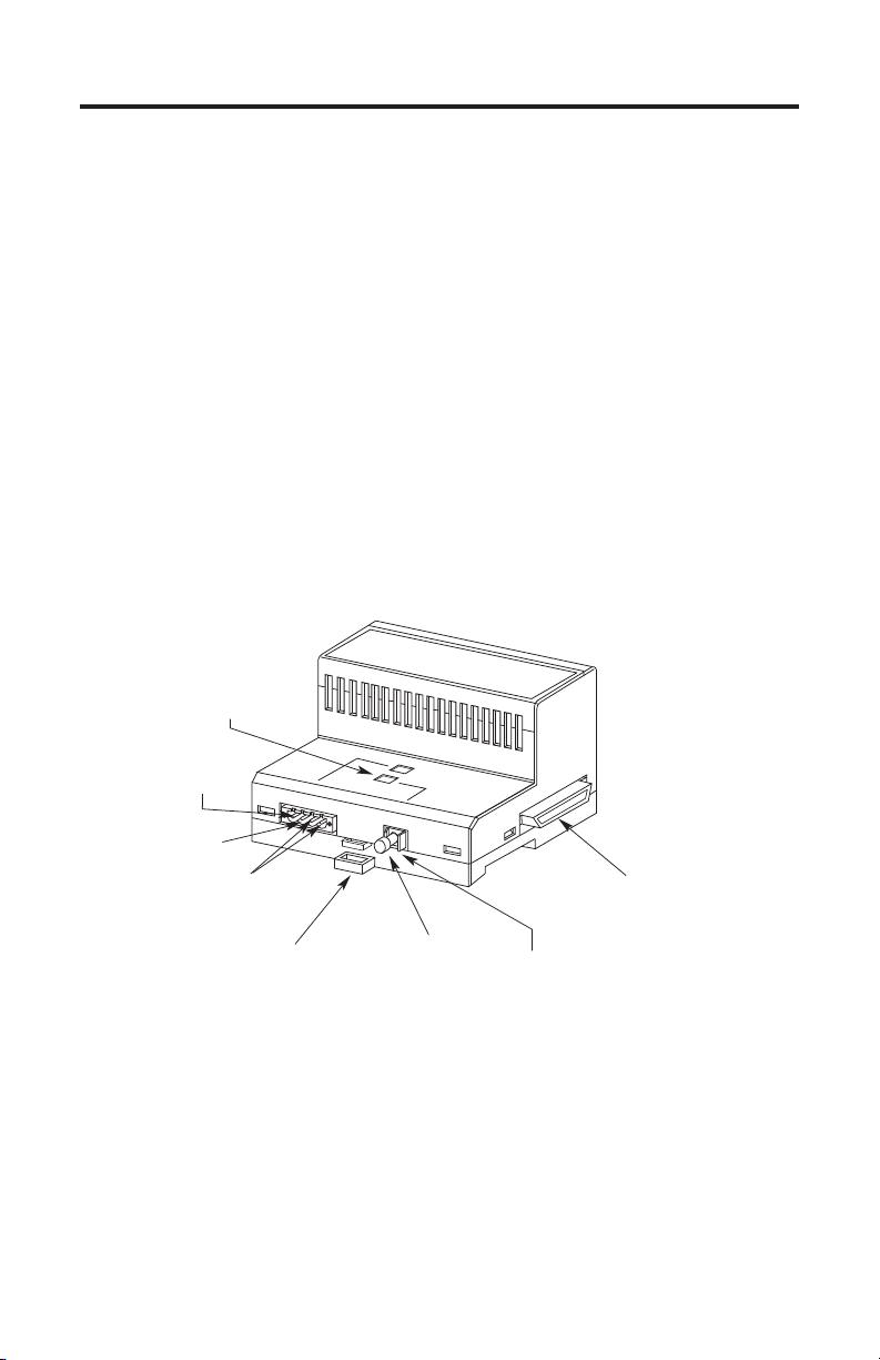
Figure 1 - Components of the base block
Indicators
+24V dc
(pin 4)
24V dc
Common
(pin 3)
Not Connected
(pins 1 and 2)
Module locking tab
Protective cap
Backplane Connector
Fiber Optic Receiver
31202-M
Publication 1751-IN001A-EN-P - March 2001
Page 4
4 SynchLink Base Block
ATTENTION
!
Prevent Electrostatic Discharge
Electrostatic discharge can damage integrated circuits or
semiconductors if you touch backplane connector pins.
Follow these guidelines when you handle the base block:
• Touch a grounded object to discharge static potential.
• Wear an approved wrist-strap grounding device.
• Do not touch the backplane connector or connector pins.
• Do not touch circuit components inside the base block.
• If available, use a static-safe work station.
• When not in use, keep the base block in its static-shield
box.
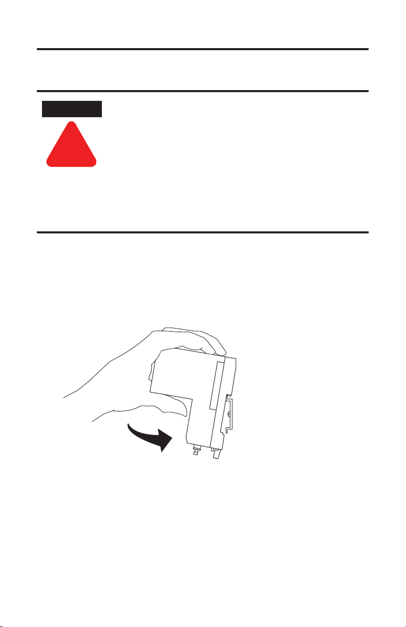
Installing the Base Block
To install the base block on the DIN rail:
1. Position the base block on the 35×7.5mm DIN rail (Allen-Bradley catalog
number 199-DR1) at a 30° angle.
Publication 1751-IN001A-EN-P - March 2001
31203a-M
Page 5
SynchLink Base Block 5
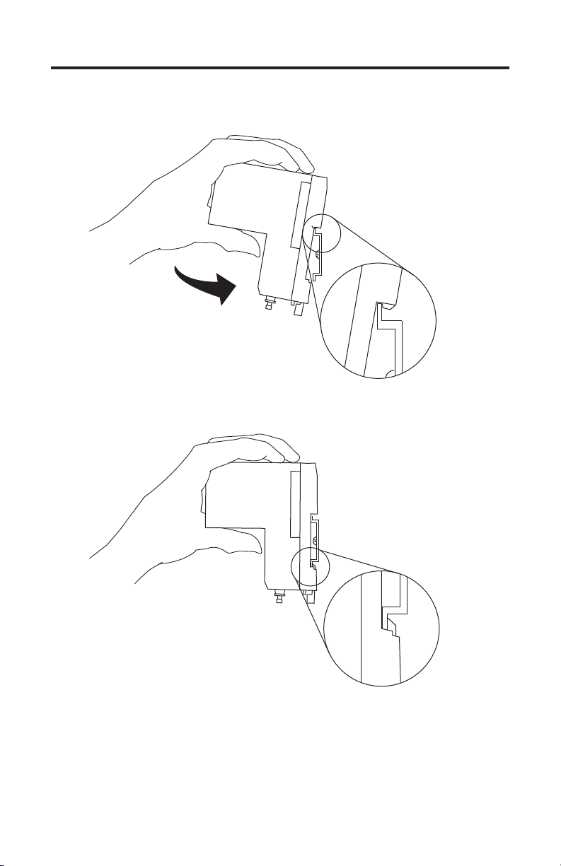
2. Hook the lip of on the rear of the base block onto the top of the DIN rail
and rotate the base block onto the rail.
31203b-M
3. Press the base block down to the DIN rail until flush.
31203c-M
The locking tab should snap into position and lock the base block to the
DIN rail. If the tab does not snap into position, follow step 4. If the tab does
snap into position, proceed to step 5.
Publication 1751-IN001A-EN-P - March 2001
Page 6

6 SynchLink Base Block
ATTENTION
!
ATTENTION
!
4. Use a screwdriver to move the locking tab down while you press the base
block flush onto the DIN rail. Release the locking tab to lock the base block
into place. If necessary, push up on the locking tab to lock the base block
into place.
5. Once you attach the base block to the DIN rail, slide the base block to the
left.
Be certain that you secure the base block and 4-port
Splitter blocks together with DIN rail anchors. Failure to
do so may result in loss of communication and/or
damage to blocks.
Failure to use the DIN rail interlocks in hazardous
location installations could cause an explosion.
The total number of 4-port splitters that can be attached to the base block
cannot exceed four.
IMPORTANT
6. Connect the block wiring as shown in Wiring the Base Block.
If you exceed the base block’s power limit, you may
cause damage to the base block.
Wiring the Base Block
To wire the base block and connect power:
Do not look directly into the fiber ports or fiber cables. Light
levels may cause damage to eyesight.
1. Connect pre-terminated fiber optic cable to the fiber optic connector shown
in Figure 1. That is, connect RxIN to SynchLink station transmitter, TxIN.
Publication 1751-IN001A-EN-P - March 2001
Page 7

SynchLink Base Block 7
2. Pre-wire the removable connector plug as shown on the base block label.
The wire length between the 24V dc power supply and the base block must
be less than 3m.
Connect To pin
+24V dc 4
24V dc Common 3
Pins 1 and 2 are not connected.
Pin 1 Pin 2 Pin 3 Pin 4
Power Supply and digital Input Connector
(front view)
31248-M
IMPORTANT
Do not connect 24V dc Common to Chassis Ground.
3. Insert the removable connector plug into the mating connector receptacle on
the base block.
Pin 4 Pin 3 Pin 2 Pin 1
Connector receptacle on base (front view)
31249a-M
4. Screw the removable connector to the base block with the left and right
mounting screws.
IMPORTANT
Make sure the base block and splitter blocks are
attached and secured prior to applying power to the
base block. Failure to do so may cause damage to the
base block and companion blocks.
Publication 1751-IN001A-EN-P - March 2001
Page 8

8 SynchLink Base Block
Indicators
Figure 2 identifies the status indicators on the base block.
Figure 2 - Status indicators
POWER ON
Status Indicators
RxIN
31222-M
Indicator When LED is ON
Power ON 24V dc power is applied to the block
RxIN optical signals are received from the SynchLink station
Publication 1751-IN001A-EN-P - March 2001
Page 9

Mounting Dimensions
Figure 3 provides mounting dimensions for the base block.
Figure 3 - Mounting dimensions
4.084 in.
(104 mm)
3.94 in.
(100 mm)
3.6 in.
(91.4 mm)
3.81 in.
(98 mm)
SynchLink Base Block 9
2.76 in.
(70.1 mm)
31232-M
Publication 1751-IN001A-EN-P - March 2001
Page 10

10 SynchLink Base Block
European Communities (EC) Directive Compliance
If this product has the CE mark it is approved for installation within the European
Union and EEA regions. It has been designed and tested to meet the following
directives.
EMC Directive
This product is tested to meet the Council Directive 89/336/EC Electromagnetic
Compatibility (EMC) by applying the following standards, in whole or in part,
documented in a technical construction file:
• EN 50081-2 EMC - Generic Emission Standard, Part 2 - Industrial Environment
• EN 50082-2 EMC - Generic Immunity Standard, Part 2 - Industrial Environment
This product is intended for use in an industrial environment.
Low Voltage Directive
This product is tested to meet Council Directive 73/23/EEC Low Voltage, by
applying the safety requirements of EN 61131-2 Programmable Controllers, Part 2 Equipment Requirements and Tests. For specific information required by EN
61131-2, see the appropriate sections in this publication, as well as the
Allen-Bradley publication Industrial Automation Wiring and Grounding Guidelines,
publication 1770-4.1.
Open style devices must be provided with environmental and safety protection by
proper mounting in enclosures designed for specific application conditions. See
NEMA Standards publication 250 and IEC publication 529, as applicable, for
explanations of the degrees of protection provided by different types of enclosure.
Publication 1751-IN001A-EN-P - March 2001
Page 11

SynchLink Base Block 11
WARNING
!
Hazardous Location information
The following information applies when operating this equipment in
hazardous locations:
Products marked “CL I, DIV 2, GP A, B, C, D” are suitable for use in Class I Division
2 Groups A, B, C, D, Hazardous Locations and nonhazardous locations only. Each
product is supplied with markings on the rating nameplate indicating the hazardous
location temperature code. When combining products within a system, the most
adverse temperature code (lowest “T” number) may be used to help determine the
overall temperature code of the system. Combinations of equipment in your system
are subject to investigation by the local Authority Having Jurisdiction at the time
of installation.
EXPLOSION HAZARD
• Do not disconnect equipment unless power has been
removed or the area is known to be nonhazardous.
• Do not disconnect connections to this equipment unless
power has been removed or the area is known to be
nonhazardous. Secure any external connections that mate
to this equipment by using screws, sliding latches, threaded
connectors, or other means provided with this product.
• Substitution of components may impair suitability for Class
I, Division 2.
• If this product contains batteries, they must only be
changed in an area known to be nonhazardous.
Publication 1751-IN001A-EN-P - March 2001
Page 12

12 SynchLink Base Block
AVERTISSEMENT
!
Informations sur l’utilisation de cet équipement en environnements
dangereux :
Les produits marqués « CL I, DIV 2, GP A, B, C, D » ne conviennent qu’à une
utilisation en environnements de Classe I Division 2 Groupes A, B, C, D dangereux
et non dangereux. Chaque produit est livré avec des marquages sur sa plaque
d’identification qui indiquent le code de température pour les environnements
dangereux. Lorsque plusieurs produits sont combinés dans un système, le code de
température le plus défavorable (code de température le plus faible) peut être
utilisé pour déterminer le code de température global du système. Les
combinaisons d’équipements dans le système sont sujettes à inspection par les
autorités locales qualifiées au moment de l’installation.
RISQUE D’EXPLOSION
• Couper le courant ou s’assurer que l’environnement est
classé non dangereux avant de débrancher l’équipement.
• Couper le courant ou s’assurer que l’environnement est
classé non dangereux avant de débrancher les connecteurs.
Fixer tous les connecteurs externes reliés à cet équipement
à l’aide de vis, loquets coulissants, connecteurs filetés ou
autres moyens fournis avec ce produit.
• La substitution de composants peut rendre cet équipement
inadapté à une utilisation en environnement de Classe 1,
Division 2.
• S’assurer que l’environnement est classé non dangereux
avant de changer les piles.
Publication 1751-IN001A-EN-P - March 2001
Page 13

SynchLink Base Block 13
Rockwell Automation Support
Rockwell Automation offers support services worldwide, with over 75 sales/support
offices, over 500 authorized distributors, and 260 authorized systems integrators
located throughout the United States alone, plus Rockwell Automation
representatives in every major country around the world. Contact your local
Rockwell Automation representative for:
• sales and order support
• product technical training
• warranty support
• support service agreements
Obtain Pre-Sales Product Support
If you need to contact Rockwell Automation for pre-sales product support, try one
of the following methods:
• Call your local Rockwell Automation representative
• Network Pre-sales support line, 1.440.646.3638 (3NET)
• Pre-Sales e-mail, RACle3net@ra.rockwell.com
Obtain Technical Product Support
If you need to contact Rockwell Automation for technical assistance, try one of the
following methods:
• Call your local Rockwell Automation representative
• Post-Sales Technical Support, 1.440.646.5800
• Fax Back system, 1.440.646.5436 (requires a touch-tone telephone)
• Web Links http://www.ab.com — as a registered member, open to
http://www.ab.com/mem/technotes/techmain.html
Publication 1751-IN001A-EN-P - March 2001
Page 14

14 SynchLink Base Block
Specifications
Power Supply To comply with CE Low Voltage directives, you must use a
Input Voltage Rating 0.6A @ 24V dc nominal
Output Voltage Rating 1.2A @ 5.1V dc nominal
Input Voltage Range 20V dc to 30V dc
Communication Rate 5M bit/s
Power Consumption 600mA maximum for external 24V supply based on worst case
Terminal Block Torque Requirements 5-7 in-lb. maximum
Environmental Conditions
Shock Operating
Fiber Optic Cable
Power Conductors
(1)
Operating Temperature 0ºC - 60ºC
Storage Temperature -40ºC - 85ºC
Relative Humidity 5 to 95%, 0ºC - 60ºC non-condensing
Non-operating
Vibration Tested 5 g @ 10 - 500Hz per IEC 68-2-6
Fiber Type 200/230 micron HCS (Hard Clad Silica)
Fiber Termination Type Versalink V-System
Assemblies Cable assemblies can be ordered from Allen-Bradley, catalog
Maximum Length 300 meters
Minimum Length 1 meter
Wire Size 12 gauge maximum, 24 gauge minimum (#12 AWG to 24
Category
Maximum Length 3 meters
Safety Extra Low Voltage (SELV) or a Protected Extra Low
Voltage (PELV) power supply to power this base block.
Use a NEC/CEC Class 2 power supply in order to comply with
UL and CSA requirements.
A regulated power supply is recommended.
block loading (four splitters)
30g peak acceleration, 11 (
50g peak acceleration, 11 (
number 1403-CFxxx (xxx = length in meters); or from Lucent
Technologies, Specialty Fiber Technologies division.
AWG), stranded
(2)
2
± 1)ms pulse width
± 1)ms pulse width
Publication 1751-IN001A-EN-P - March 2001
Page 15

SynchLink Base Block 15
Agency Certifications
When product is marked:
Listed Industrial Control Equipment
Certified Process Control Equipment
Certified Class I, Division 2, Group A, B, C, D
Marked for all applicable directives
marked for all applicable acts
(1)
This product must be mounted within a suitable system enclosure to prevent personal injury resulting from accessibility to
live parts. The interior of this enclosure must be accessible only by the use of a tool. This industrial control equipment is
intended to operate in a Pollution Degree 2 environment, in overvoltage category II applications, (as defined in IEC
publication 664A) at altitudes up to 2000 meters without derating.
(2)
You use this category information for planning conductor routing as described in publication 1770-4.1, “Industrial
Automation Wiring and Grounding Guidelines.”
N223
Publication 1751-IN001A-EN-P - March 2001
Page 16

Notes:
Allen-Bradley, ControlLogix, PowerFlex 700s, and SynchLink are trademarks of Rockwell Automation.
Publication 1751-IN001A-EN-P - March 2001 PN 957345-10
© 2001 Rockwell International Corporation. Printed in the U.S.A.
 Loading...