

Page 1
SMC Controllers
Bulletin 150
Application
and Product
Guide
Page 2
Please Read!
This manual is intended to guid qualified personnel in th
installation and operation of this product.
Because of the variety of uses for this equipment and because of the
differences between this solid-state equipment and electromechanical
equipment, the user of and those responsible for applying this
equipment must satisfy themselves as to the acceptability of each
application and use of the equipment. In no event will Allen-Bradley
Company, Inc. be responsible or liable for indirect or consequential
damages resulting from the use or application of this equipment.
The illustrations shown in this manual are intended solely to illustrate
the text of this manual. Because of the many variables and
requirements associated with any particular installation, the AllenBradley Company, Inc. cannot assume responsibility or liability for
actual use based on t he illu str ative uses and applications.
No patent liability is assumed by Allen-Bradley Company, Inc., with
respect to use of information, circuits, or equipment described in this
text.
Reproduction of the content of this manual, in whole or in part,
without written permission of the Allen-Bradley Company, Inc. is
prohibited.
For Smart M otor Controller technical support, contact your AllenBradley representative.
In the United States and Canada you may also call 1-800-765-SMCS (765-7627) for assistance during the hours of
8:00 AM to 12:00 noon and 1:00 PM to 4:30 PM (Central Time Zone) from Monday through Friday.
Important User Information
The information in this manual is organized in numbered chapters.
Read each chapter in sequence and perform procedures when you are
instructed t o do so. Do not proceed to t he next c ha pter u n til you have
complete d al l pr ocedures.
Throughout this manual we use notes to make you aware of safety
considerations:
ATTENTION: Identifies information about practices
or circumstances t hat c an le ad to personal injury or
!
Attentions help you:
• identify a hazard
• avoid the hazard
• recogniz e t he conse quences
Important: Identifies information that is especially important for
STC, SMC-2, SMC PLUS, SMC Dialog Plus, SMB, and Accu-Stop are trademarks of the Allen-Bradley
Company, Inc. DeviceNet is a trademark of the
death, property damage, or economic loss.
successful application and understanding of this product.
Open DeviceNet
Vendor Association, Inc.
Page 3

Table of Contents
Chapter 1 STC Starting Torque Controller
Description . . . . . . . . . . . . . . . . . . . . . . . . . . . . . . . . . . 1-1
Modes of Operation . . . . . . . . . . . . . . . . . . . . . . . . . . . . 1-2
Across-the-Line Response . . . . . . . . . . . . . . . . . . . . . 1-2
STC Controller Response . . . . . . . . . . . . . . . . . . . . . . 1-2
Across-the-Line Response Versus STC
Controller Response . . . . . . . . . . . . . . . . . . . . . . . 1-2
Features . . . . . . . . . . . . . . . . . . . . . . . . . . . . . . . . . . . . 1-3
Adjustments . . . . . . . . . . . . . . . . . . . . . . . . . . . . . . . . . . 1-3
Wiring Diagrams . . . . . . . . . . . . . . . . . . . . . . . . . . . . . . 1-4
Suitable Replacement . . . . . . . . . . . . . . . . . . . . . . . . . . 1-6
Applications . . . . . . . . . . . . . . . . . . . . . . . . . . . . . . . . . . 1-6
Chapter 2 SMC-2 Smart Motor Controller
Description . . . . . . . . . . . . . . . . . . . . . . . . . . . . . . . . . . 2-1
Modes of Operation . . . . . . . . . . . . . . . . . . . . . . . . . . . . 2-1
Soft Start . . . . . . . . . . . . . . . . . . . . . . . . . . . . . . . . . . 2-2
Current Limit Start . . . . . . . . . . . . . . . . . . . . . . . . . . . 2-2
Full Voltage Start . . . . . . . . . . . . . . . . . . . . . . . . . . . . 2-3
Features . . . . . . . . . . . . . . . . . . . . . . . . . . . . . . . . . . . . 2-3
Fault Trips . . . . . . . . . . . . . . . . . . . . . . . . . . . . . . . . . 2-3
Adjustments . . . . . . . . . . . . . . . . . . . . . . . . . . . . . . . . . . 2-4
Wiring Diagram . . . . . . . . . . . . . . . . . . . . . . . . . . . . . . . 2-7
Series Controller . . . . . . . . . . . . . . . . . . . . . . . . . . . . 2-7
Options . . . . . . . . . . . . . . . . . . . . . . . . . . . . . . . . . . . . . 2-8
Description of Interface Options . . . . . . . . . . . . . . . . . 2-8
Soft Stop Option . . . . . . . . . . . . . . . . . . . . . . . . . . . . . 2-8
Wiring Diagram with Interface Option . . . . . . . . . . . . . 2-9
Overload Relay Option . . . . . . . . . . . . . . . . . . . . . . . .2-10
Applications . . . . . . . . . . . . . . . . . . . . . . . . . . . . . . . . . .2-10
Chapter 3 SMC Dialog Plus Smart Motor Controller
Description . . . . . . . . . . . . . . . . . . . . . . . . . . . . . . . . . . 3-1
Starting Methods . . . . . . . . . . . . . . . . . . . . . . . . . . . . . . 3-2
Soft Start with Selectable Kickstart . . . . . . . . . . . . . . . 3-2
Current Limit Start . . . . . . . . . . . . . . . . . . . . . . . . . . . 3-3
Dual Ramp Start . . . . . . . . . . . . . . . . . . . . . . . . . . . . . 3-3
Full Voltage Start . . . . . . . . . . . . . . . . . . . . . . . . . . . . 3-4
Page 4

toc–ii
Table of Contents
Chapter 3 (cont.)
Features . . . . . . . . . . . . . . . . . . . . . . . . . . . . . . . . . . . . . 3-4
LCD Display . . . . . . . . . . . . . . . . . . . . . . . . . . . . . . . . 3-4
Keypad Programming . . . . . . . . . . . . . . . . . . . . . . . . . 3-4
Electronic Overload . . . . . . . . . . . . . . . . . . . . . . . . . . . 3-5
Built-in Communication Port . . . . . . . . . . . . . . . . . . . . 3-5
Stall Protection and Jam Detection . . . . . . . . . . . . . . . 3-6
Phase Rebalance . . . . . . . . . . . . . . . . . . . . . . . . . . . . 3-7
Metering . . . . . . . . . . . . . . . . . . . . . . . . . . . . . . . . . . . 3-7
Fault Indication . . . . . . . . . . . . . . . . . . . . . . . . . . . . . . 3-7
Auxiliary Contacts . . . . . . . . . . . . . . . . . . . . . . . . . . . . 3-8
Energy Saver . . . . . . . . . . . . . . . . . . . . . . . . . . . . . . . 3-8
Modular Design . . . . . . . . . . . . . . . . . . . . . . . . . . . . . 3-8
Control Terminal Description . . . . . . . . . . . . . . . . . . . . 3-9
Power Supply Board . . . . . . . . . . . . . . . . . . . . . . . . 3-9
Logic Board . . . . . . . . . . . . . . . . . . . . . . . . . . . . . . 3-9
Adjustments . . . . . . . . . . . . . . . . . . . . . . . . . . . . . . . . . .3-10
Soft Start without Options . . . . . . . . . . . . . . . . . . . . . .3-10
Current Limit Start without Options . . . . . . . . . . . . . . .3-11
Dual Ramp Start without Options . . . . . . . . . . . . . . . .3-12
Full Voltage Start without Options . . . . . . . . . . . . . . . .3-14
Typical Wiring Diagrams (without options) . . . . . . . . . . .3-15
Control Options . . . . . . . . . . . . . . . . . . . . . . . . . . . . . . .3-19
Soft Stop Option . . . . . . . . . . . . . . . . . . . . . . . . . . . . .3-19
Programming - Soft Start with Soft Stop Option . . . . .3-21
Pump Control Option . . . . . . . . . . . . . . . . . . . . . . . . .3-23
Programming - Pump Control Starting and Stopping . .3-25
Preset Slow Speed Option . . . . . . . . . . . . . . . . . . . . .3-27
Programming - Soft Start with Preset Slow
Speed Option . . . . . . . . . . . . . . . . . . . . . . . . . . . . .3-29
SMB Smart Motor Braking Option . . . . . . . . . . . . . . . .3-32
Programming - Soft Start with SMB Smart Motor
Braking Option . . . . . . . . . . . . . . . . . . . . . . . . . . .3-34
Accu-Stop/Slow Speed with Braking Option . . . . . . . .3-36
Accu-Stop Option . . . . . . . . . . . . . . . . . . . . . . . . . . . .3-37
Programming - Soft Start with Accu-Stop Option. . . . .3-38
Accu-Stop/Slow Speed with Braking Option . . . . . . . .3-41
Slow Speed with Braking Capability . . . . . . . . . . . . . .3-42
Programming - Soft Start with Slow Speed
with Braking Capability . . . . . . . . . . . . . . . . . . . . .3-43
Chapter 4 Application Profiles for the SMC Dialog
Plus Controller
Page 5

Table of Contents
Chapter 5 SMC Dialog Plus Controller
Special Application Considerations
SMC Dialog Plus Controllers in Drive Applications . . . . . . 5-1
Use of Protective Modules . . . . . . . . . . . . . . . . . . . . . . . 5-1
Current Limit Fuses (Overcurrent Protection of SCRs) . . . 5-3
Motor Overload Protection. . . . . . . . . . . . . . . . . . . . . . . . 5-4
Phase Rebalance . . . . . . . . . . . . . . . . . . . . . . . . . . . . . . 5-4
Stall Protection and Jam Detection . . . . . . . . . . . . . . . . . 5-5
Built-in SCANport Communications . . . . . . . . . . . . . . . . 5-5
Power Factor Capacitors. . . . . . . . . . . . . . . . . . . . . . . . . 5-6
Multi-motor Applications . . . . . . . . . . . . . . . . . . . . . . . . 5-8
Special Motors . . . . . . . . . . . . . . . . . . . . . . . . . . . . . . . . 5-8
Wye-Delta . . . . . . . . . . . . . . . . . . . . . . . . . . . . . . . . . 5-8
Part Winding . . . . . . . . . . . . . . . . . . . . . . . . . . . . . . . . 5-9
Wound Rotor . . . . . . . . . . . . . . . . . . . . . . . . . . . . . . . 5-9
Synchronous . . . . . . . . . . . . . . . . . . . . . . . . . . . . . . . 5-9
Altitude De-rating . . . . . . . . . . . . . . . . . . . . . . . . . . . . . .5-10
Isolation Contactor . . . . . . . . . . . . . . . . . . . . . . . . . . . . .5-10
SMC Dialog Plus Controller with Bypass Contactor (BC) .5-11
SMC Dialog Plus Controller with Reversing Contactor . . .5-11
SMC Dialog Plus Controller as a Bypass to an AC Drive .5-12
SMC Dialog Plus Controller with a Bulletin 1410
Motor Winding Heater . . . . . . . . . . . . . . . . . . . . . . . . . .5-13
Motor Torque Capabilities with SMC Dialog Plus
Controller Options . . . . . . . . . . . . . . . . . . . . . . . . . . . . .5-14
SMB Smart Motor Braking . . . . . . . . . . . . . . . . . . . . .5-14
Preset Slow Speed . . . . . . . . . . . . . . . . . . . . . . . . . . .5-14
Accu-Stop . . . . . . . . . . . . . . . . . . . . . . . . . . . . . . . . .5-15
Energy Saver . . . . . . . . . . . . . . . . . . . . . . . . . . . . . . . . .5-15
Energy Saver Operation . . . . . . . . . . . . . . . . . . . . . . .5-15
Background . . . . . . . . . . . . . . . . . . . . . . . . . . . . . . . .5-16
Application Requirements . . . . . . . . . . . . . . . . . . . . . .5-17
Preliminary Estimates . . . . . . . . . . . . . . . . . . . . . . . . .5-17
toc–iii
Chapter 6 SMC Product Line Applications Matrix
Description . . . . . . . . . . . . . . . . . . . . . . . . . . . . . . . . . . . 6-1
Mining and Metals . . . . . . . . . . . . . . . . . . . . . . . . . . . . . 6-2
Food Processing . . . . . . . . . . . . . . . . . . . . . . . . . . . . . . . 6-3
Pulp and Paper . . . . . . . . . . . . . . . . . . . . . . . . . . . . . . . . 6-4
Petrochemical . . . . . . . . . . . . . . . . . . . . . . . . . . . . . . . . 6-5
Transportation and Machine Tool . . . . . . . . . . . . . . . . . . 6-6
OEM Specialty Machine . . . . . . . . . . . . . . . . . . . . . . . . . 6-7
Lumber and Wood Products . . . . . . . . . . . . . . . . . . . . . . 6-8
Water/Wastewater Treatment and Municipalities . . . . . . 6-9
Page 6

toc–iv
Table of Contents
Chapter 7 Design Philosophy
Philosophy . . . . . . . . . . . . . . . . . . . . . . . . . . . . . . . . . . . 7-1
Line Voltage Conditions . . . . . . . . . . . . . . . . . . . . . . . . . 7-1
Current and Thermal Ratings . . . . . . . . . . . . . . . . . . . . . 7-1
Mechanical Shock and Vibration . . . . . . . . . . . . . . . . . . . 7-1
Set-up . . . . . . . . . . . . . . . . . . . . . . . . . . . . . . . . . . . . . . 7-2
Chapter 8 Reduced Voltage Starting
Introduction to Reduced Voltage Starting . . . . . . . . . . . . 8-1
Reduced Voltage . . . . . . . . . . . . . . . . . . . . . . . . . . . . . . 8-2
Solid-state . . . . . . . . . . . . . . . . . . . . . . . . . . . . . . . . . . . 8-6
Chapter 9 Solid-state Starters Using SCRs
Solid-state Starters Using SCRs . . . . . . . . . . . . . . . . . . . 9-1
Chapter 10 Reference
Introduction . . . . . . . . . . . . . . . . . . . . . . . . . . . . . . . . . .10-1
Motor Output Speed/Torque/Horsepower . . . . . . . . . . . .10-1
Torque and Horsepower . . . . . . . . . . . . . . . . . . . . . . . . .10-1
Locked-Rotor Torque (LRT) . . . . . . . . . . . . . . . . . . . . .10-3
Pull-Up Torque (PUT) . . . . . . . . . . . . . . . . . . . . . . . . . .10-3
Breakdown Torque (BT) . . . . . . . . . . . . . . . . . . . . . . .10-3
Full-load Torque (FLT) . . . . . . . . . . . . . . . . . . . . . . . . .10-4
Full-load Current . . . . . . . . . . . . . . . . . . . . . . . . . . . .10-4
Locked-rotor Current . . . . . . . . . . . . . . . . . . . . . . . . .10-4
kVA per Horsepower is Calculated as Follows: . . . . . .10-5
Motor Output for NEMA Design Designations
Polyphase 1–500 HP . . . . . . . . . . . . . . . . . . . . . . . . . . .10-7
Calculating Torque (Acceleration Torque Required for
Rotating Motion) . . . . . . . . . . . . . . . . . . . . . . . . . . . . . . .10-11
Calculating Horsepower . . . . . . . . . . . . . . . . . . . . . . . . .10-12
Inertia . . . . . . . . . . . . . . . . . . . . . . . . . . . . . . . . . . . . . .10-12
Torque Formulas . . . . . . . . . . . . . . . . . . . . . . . . . . . . . .10-13
AC Motor Formulas . . . . . . . . . . . . . . . . . . . . . . . . . . . .10-14
Torque Characteristics on Common Applications . . . . . .10-15
Electrical Formulas . . . . . . . . . . . . . . . . . . . . . . . . . . . . .10-17
Ohm’s Law: . . . . . . . . . . . . . . . . . . . . . . . . . . . . . . . .10-17
Power in DC Circuits: . . . . . . . . . . . . . . . . . . . . . . . . .10-17
Calculating Motor Amperes . . . . . . . . . . . . . . . . . . . . . .10-18
Other Formulas . . . . . . . . . . . . . . . . . . . . . . . . . . . . . . .10-19
Calculating Accelerating Force for Linear Motion: . . . .10-19
Page 7

Table of Contents
Chapter 10 (cont.)
Engineering Constants . . . . . . . . . . . . . . . . . . . . . . . . . .10-19
Temperature . . . . . . . . . . . . . . . . . . . . . . . . . . . . . . . .10-19
Length . . . . . . . . . . . . . . . . . . . . . . . . . . . . . . . . . . . .10-19
Weight. . . . . . . . . . . . . . . . . . . . . . . . . . . . . . . . . . . . .10- 20
Power . . . . . . . . . . . . . . . . . . . . . . . . . . . . . . . . . . . . .10-20
Area . . . . . . . . . . . . . . . . . . . . . . . . . . . . . . . . . . . . . .10-20
Mathematic . . . . . . . . . . . . . . . . . . . . . . . . . . . . . . . .10-20
Pressure . . . . . . . . . . . . . . . . . . . . . . . . . . . . . . . . . . .10-20
Volume . . . . . . . . . . . . . . . . . . . . . . . . . . . . . . . . . . . .10-21
Temperature . . . . . . . . . . . . . . . . . . . . . . . . . . . . . . . .10-21
Length . . . . . . . . . . . . . . . . . . . . . . . . . . . . . . . . . . . .10-21
Weight . . . . . . . . . . . . . . . . . . . . . . . . . . . . . . . . . . . .10-21
Electrical . . . . . . . . . . . . . . . . . . . . . . . . . . . . . . . . . .10-21
Power/Energy . . . . . . . . . . . . . . . . . . . . . . . . . . . . . . .10-21
Work/Inertia . . . . . . . . . . . . . . . . . . . . . . . . . . . . . . . .10-22
Area . . . . . . . . . . . . . . . . . . . . . . . . . . . . . . . . . . . . . .10-22
Rotation/Rate . . . . . . . . . . . . . . . . . . . . . . . . . . . . . . .10-22
Mathematic . . . . . . . . . . . . . . . . . . . . . . . . . . . . . . . .10-22
Pressure . . . . . . . . . . . . . . . . . . . . . . . . . . . . . . . . . . .10-22
Volume . . . . . . . . . . . . . . . . . . . . . . . . . . . . . . . . . . . .10-22
Conversion Factors . . . . . . . . . . . . . . . . . . . . . . . . . . . . .10-23
toc–v
Page 8
SMC Controllers
The Allen-Bradley SMC Controller lines offer a broad range of
products for starting or stopping AC induction motors from 1/3 HP to
6,000 HP. Th e innovative features, compact d esign, and available
enclosed controllers meet world-wide industry requirements for
controlling motors. Whether you need to control a single motor or an
integrated automation system, our range of controllers meet your
required needs with the Starting Torque Controller (STC) and Smart
Motor Controller family (SMC-2, SMC PLUS, and SMC Dialog
Plus).
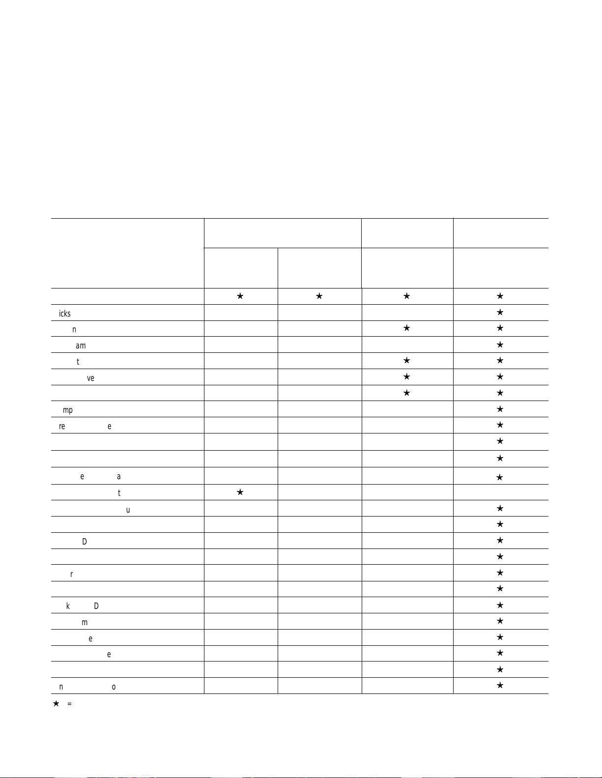
Features
Soft Start
Kickstart
Current Limit Start
Dual Ramp Start
Full Voltage Start
Energy Saver
Soft Stop
Pump Control
Preset Slow Speed
SMB Smart Motor Braking
Accu-Stop
Slow Speed with Braking
Single-phase Operation
Normal/Up-to-speed Aux
Fault Contact
Modular Design
Overload Protection
Metering
Communication
Backlit LCD Display
Programming Keypad
Phase Reversal
Phase Rebalance
Jam Detection
Underload Detection
STC Controller SMC–2 Controller
100–240V
1-phase
1–22A
200–600V
3-phase
1–22A
200–600V
1–97A
SMC Dialog Plus
Controller
200–600V
1–1000A
①
= Available
① Included with the Accu-Stop option
Page 9
STC Starting Torque Controller
Chapter 1
Description
The STC Starting Torque Controller is designed for low horsepower
single-phase and three-phase squirrel cage induction motors. It is
intended to relieve the starting torque surge encountered in typical
across-the-line starting. This will provide smoother starts and
decrease downtime due to shock and vibration related problems.
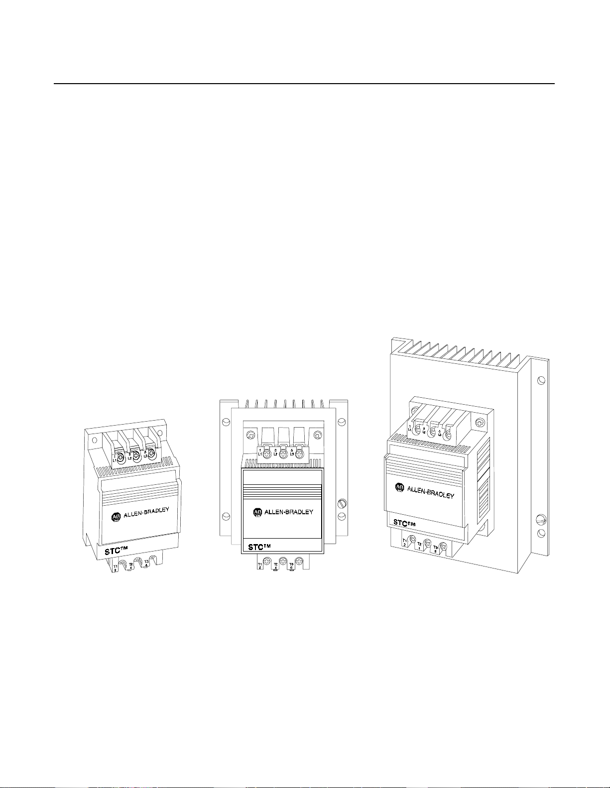
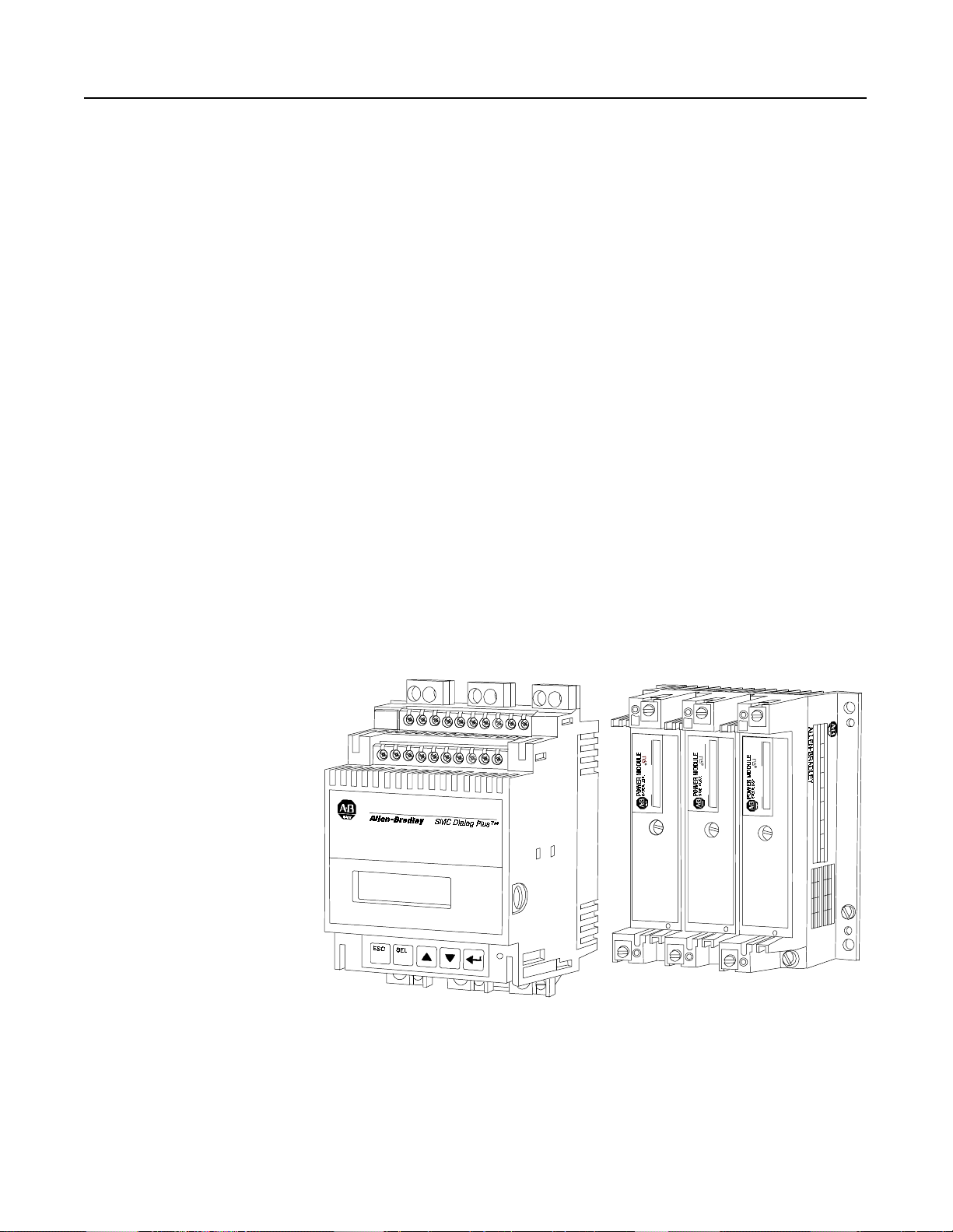
The STC is a global product available in three current rated sizes: 11,
16, an d 22 Amp, with voltage rang e s f rom 100–60 0V , 50/60 Hz., UL
Listed, CSA Approved, and CE labeled. Its compact design makes
new installations as well as retrofitting easy. Setting the initial torque
and ramp time of the controller is accomplished with digital rotary
switches.
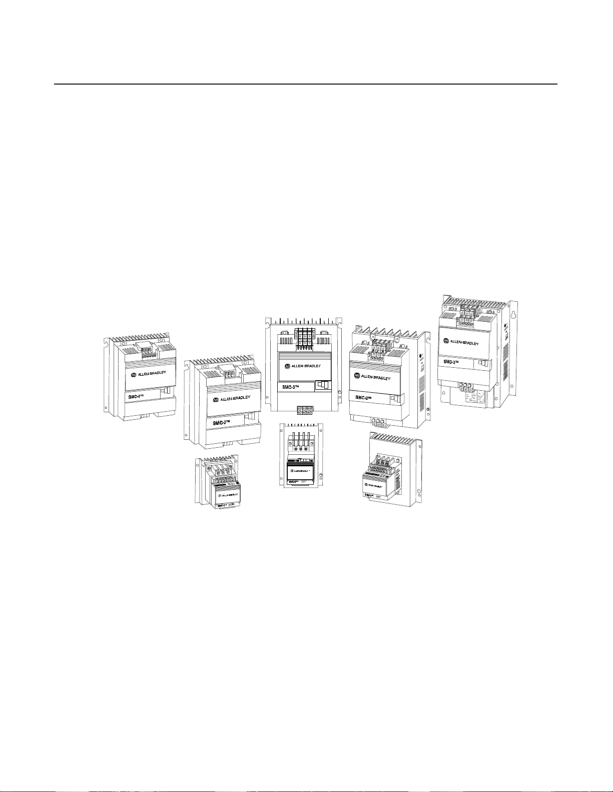
Figure 1.1 STC Controller (11, 16, and 22 Amps)
Page 10
1-2
STC Starting Torque Controller
Modes of Operation
Across-the-Line Response
Excessive motor starting torque can damage the motor and driv
equipment. Figure 1.2 illustrates the torque developed in a typical
across-the-line start.
Figure 1.2 Torque Developed in a Typical Across-the-Line Start
10
75
50
Tor qu e
NM
25
0
-25
-50
0 0.1 0.2 0.3 0.4 0.5 0.6 0.7
Time (sec.)
STC Controller Response
The STC controller r educes the ma gnitu de of st ar ting torque surges as
illustrated in Figure 1.3. This limits the starting shock to the motor
and drive train.
Figure 1.3 STC Controller Respons
10
75
Tor qu
NM
50
25
0
-25
-50
0 0.1 0.2 0.3 0.4 0.5 0.6 0.7
Time (sec.)
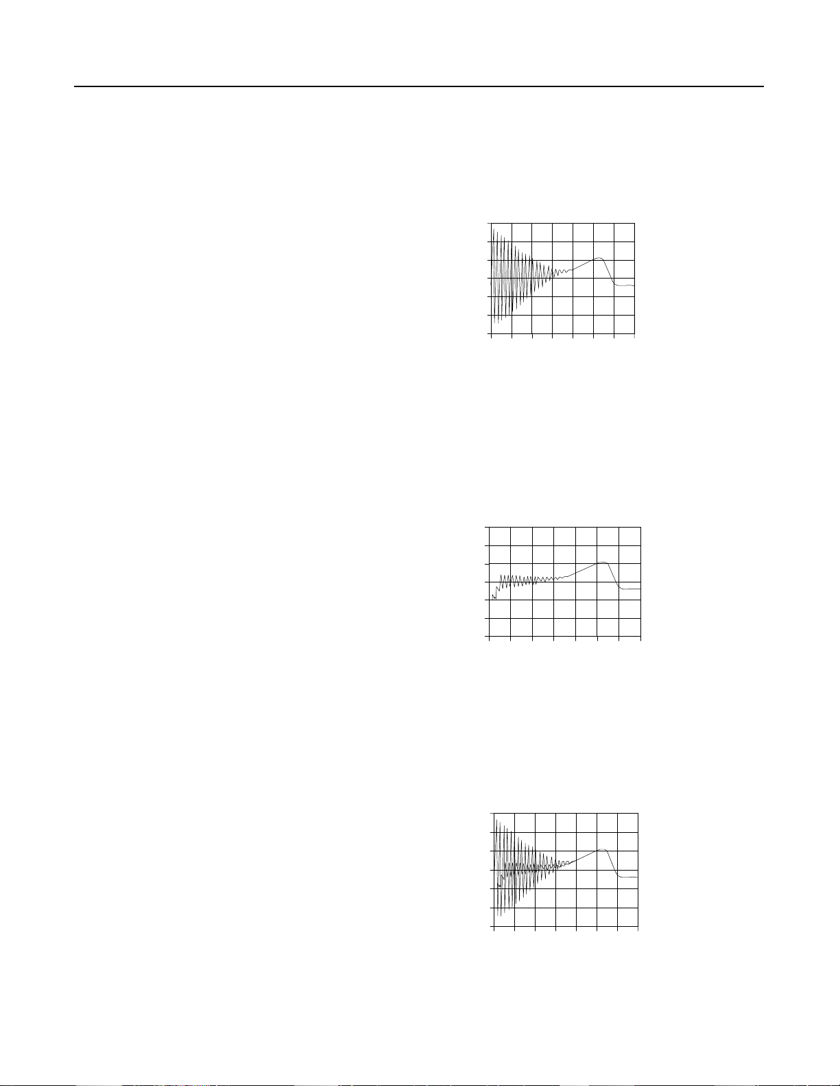
Across-the-Line Response Versus STC Controller Response
Figure 1.4 compares a typical across-the-line start response and the
STC control ler respo nse.
Figure 1.4 Across-the-Line Response Versus STC Controller Response
100
75
50
Torque
NM
25
0
-25
-50
0 0.1 0.2 0.3 0.4 0.5 0.6 0.7
Time (sec.)
Page 11
STC Starting Torque Controller
1-3
Features
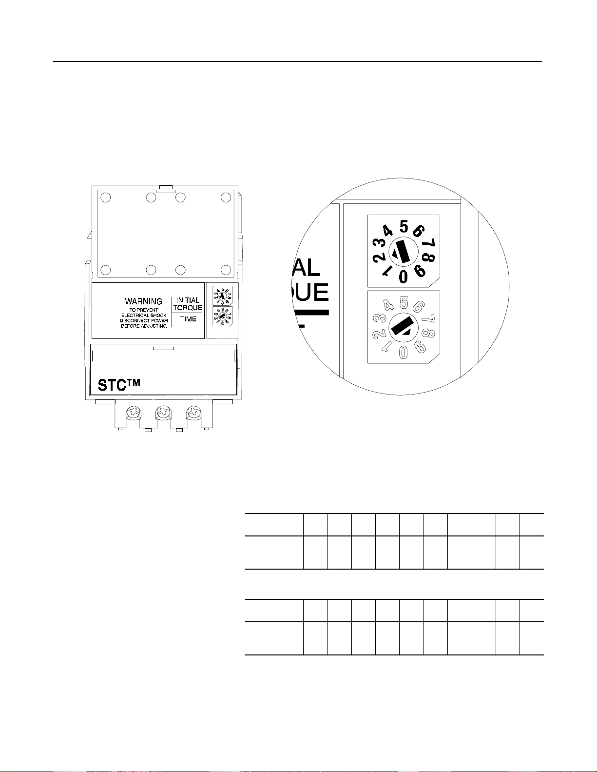
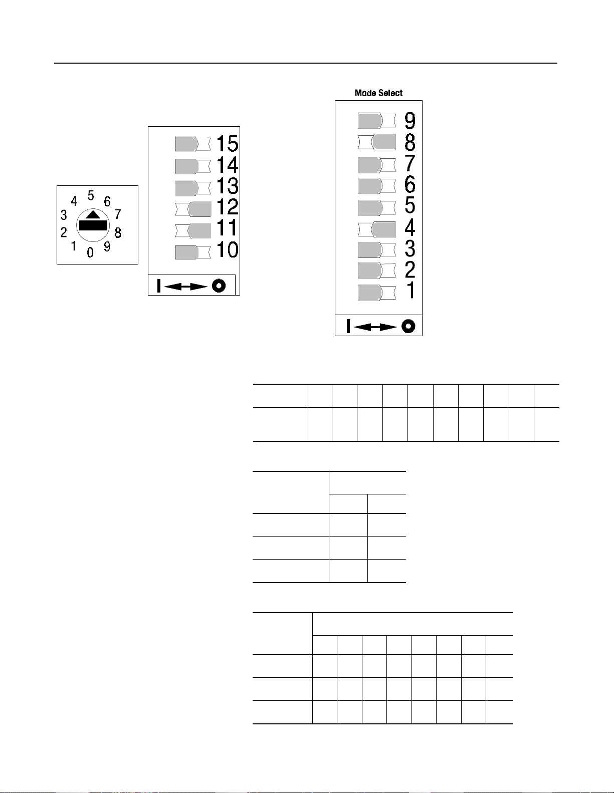
Adjustments
The STC controller is a compact device with feed through wiring for
ease of installation. To set up the controller, ad just the digital rotary
switches. The initial torque value is set between 10 and 80% of
locked rotor torque. The voltage ramp time is adjustable from 0.1 to
4.5 seconds. This flexible combination enables the STC controller to
be installed in a wide variety of applications.
Figure 1.5 STC Controller Adjustments
T1
T2
2
T3
4
6
Digital Rotary switches for easy adjustments
Table 1.A Initial Torque Level (Nominal)
Position
% of Locked
Rotor Torque
Table 1.B
Position
Time
(Seconds)
0123456789
10 15 20 25 30 40 50 60 70 80
Voltage Ramp Time (Nominal)
0123456789
0.1 0.5 1.0 1.5 2.0 2.5 3.0 3.5 4.0 4.5
(With Initial Torque Set At 0)
Page 12
1-4
STC Starting Torque Controller
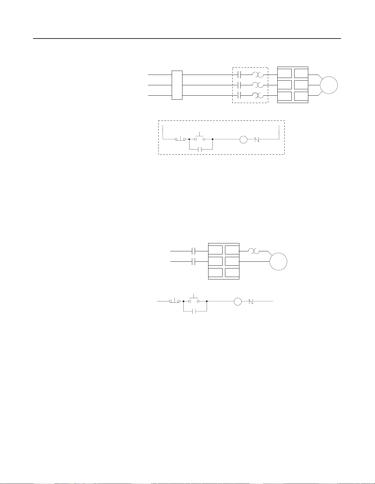
Wiring Diagrams
Figure 1.6 Typical Wiring Diagrams for STC Controller in Three-phase
Applications
M
L1/1
Power Input
3-Phase
Protection
Branch
➀
Start
Stop
➀
➀
M
➀
Existing Motor
Starter
➀
O.L.
M
Starting Torque
➀
➀
T1/2
L2/3
T2/4
L3/5
T3/6
Controller
Existing Control Circuit
Customer supplied
➀
Figure 1.7 Typical Wiring Diagrams for STC Controller in Single-phase
Applications
Starting Torqu
M
L1
L2
M
Control ler
L1/1
T1/2
L2/3
T2/4
➀
L3/5
T3/6
O.L.
➀
1Ø
Motor
➀
Motor
➀
Start
M
➀
➀
➀
O.L.
M
➀
➀
Stop
Customer supplied
➀
Page 13
STC Starting Torque Controller
Stop
➀
F
➀
F
➀
R
➀
R
➀
➀
➀
➀
➀
Forward
➀
Reverse
➀
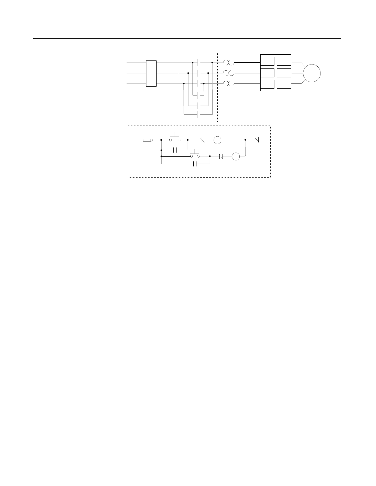
3-Phase
F
R
Power Input
Branch
Protection
➀
Overload Rela
(O.L.)
➀
Starting Torque
Contro ller
➀
F
R
Figure 1.8 Typical Wiring Diagrams for STC Controller – Reversing
L1/1
T1/2
Motor
Customer supplied
O.L.
L2/3
T2/4
L3/5
T3/6
Existing Control Circuit
1-5
Page 14

1-6
STC Starting Torque Controller
Suitable Replacement
Applications
The STC controller is a suitable replacement for:
• W ye-delta Starters
• Resistor Ballast Starters
• Line Reactors
• Clutches
• Flywheels
• Fluid Coup lings
• Other Mechanical and Electrical Soft Start Devices
In this section a few of the many STC controller applications are
described.
Illustrations are included to he l p identify the particular application.
Motor ratings are specified but this may vary in other typical
applications.
Typical applications include:
• Bridge Cranes
• Trolleys
• Monorails
• Shrink Wrap Machines
• Overhead Doors
• Conveyor
• Material Handling Equipment
• Compressors
• Fans and Pumps
• Lifts
• Elevators
• Grinders
•Mixers
Page 15
STC Starting Torque Controller
1-7
Applications (cont.)
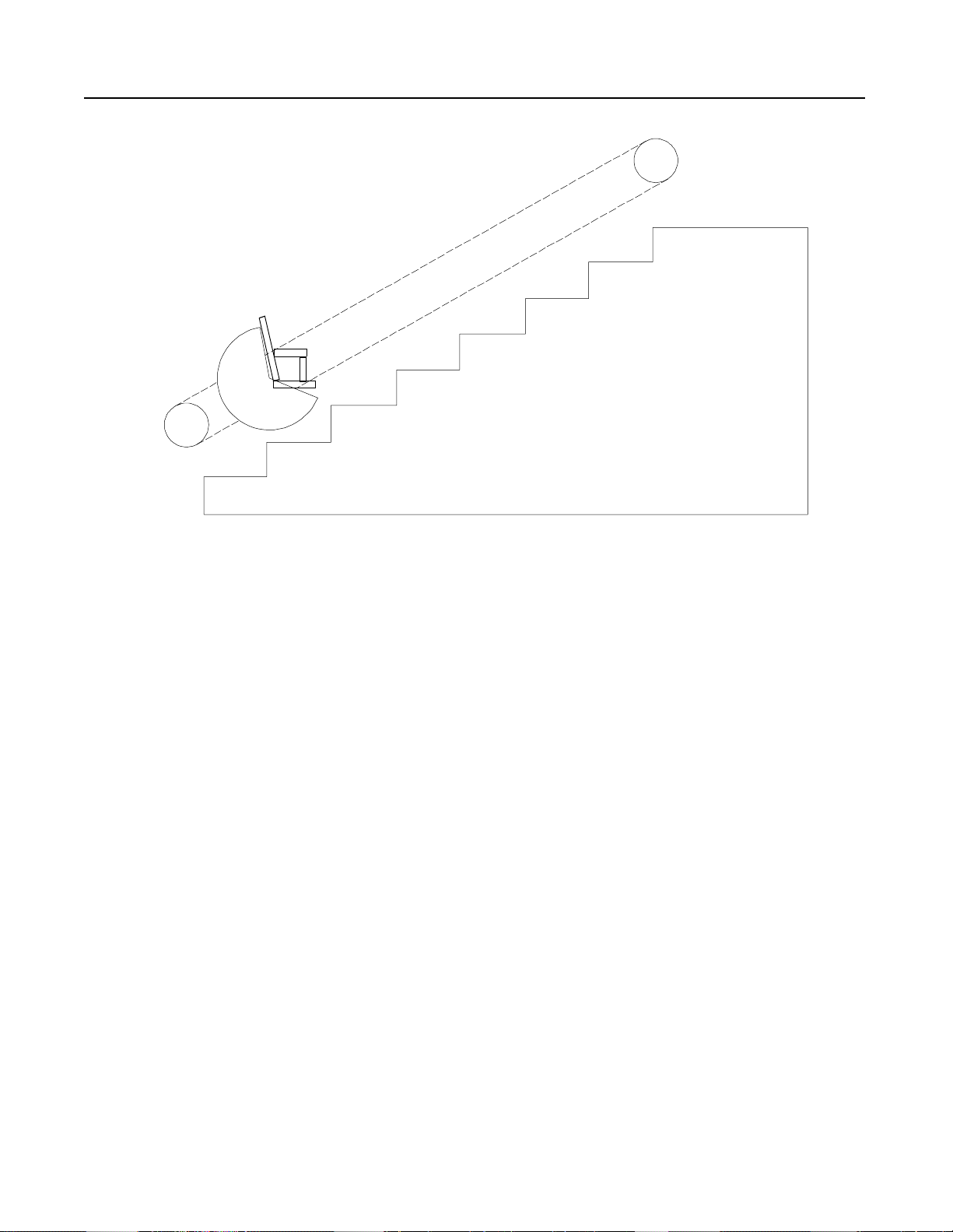
Figure 1.9 Chair Elevator
Problem: A single-pha se chain driven chair elev ator was started
across-the-line. The starting torque caused the chair to
lurch during the start and occasionally caused chain
alignment problems.
Solution: An STC controller was installed to provide controlled
acceleration.This minimized the mechanical shock
encountered during across-the-line starting and reduced
alignment problems. It also allowed for regularly
scheduled preventive maintenance inspections, rather
than emergency maintenance repair.
Page 16
1-8
STC Starting Torque Controller
Applications (cont.)
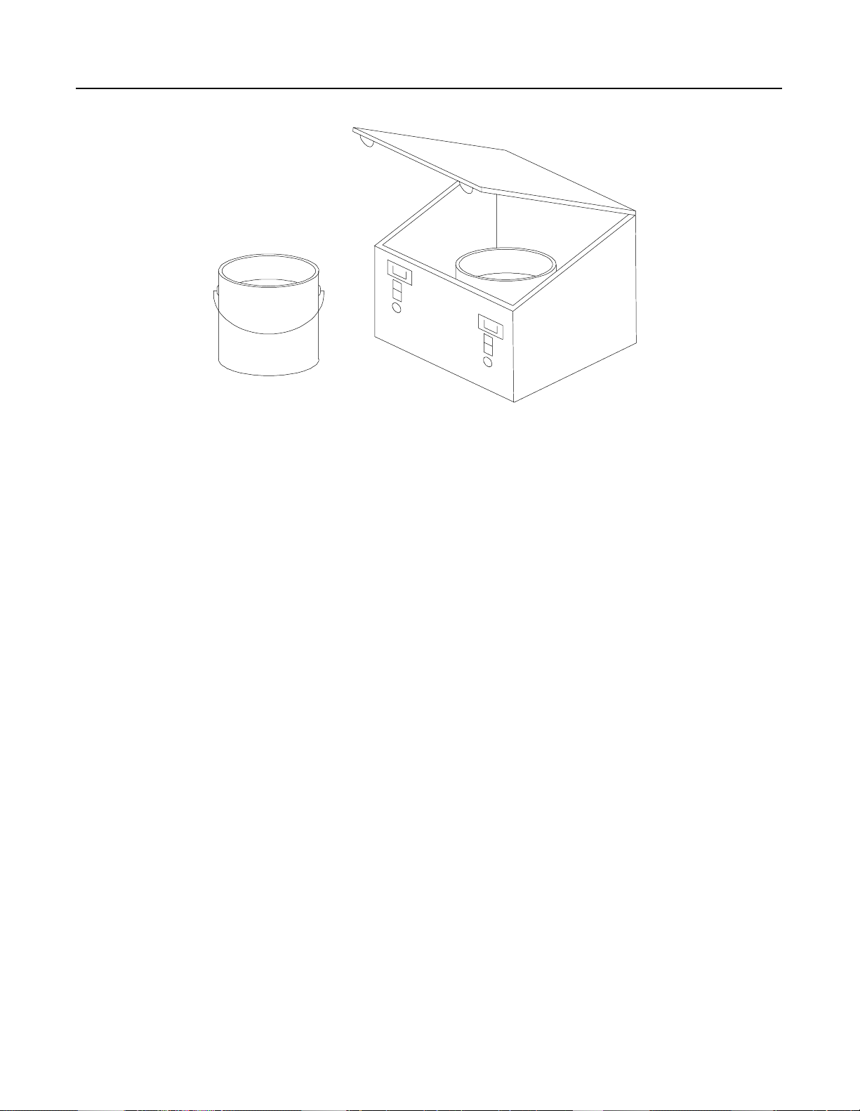
Figure 1.10 Paint Shaker
Problem: The commercial paint shaker was operated with a single
phase motor and used across-the-line starting. This
method of starting caused the facility’s line voltage to
dip. The building’s fluorescent lighting, with electronic
ballasts, was extremely sensitive to line voltage dips and
would momentarily shut off when the paint shaker was
started.
Solution: A single-phase STC controller was used to provide a soft
start to t he paint shaker. The ramp time was set to three
seconds, thereby eliminating the line voltage dip.
Page 17
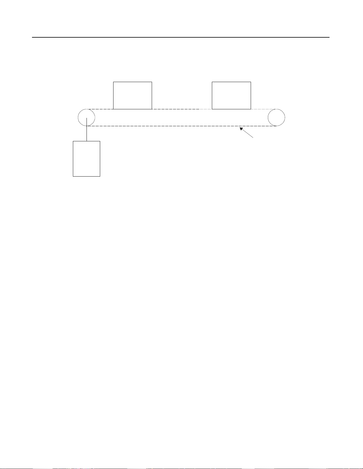
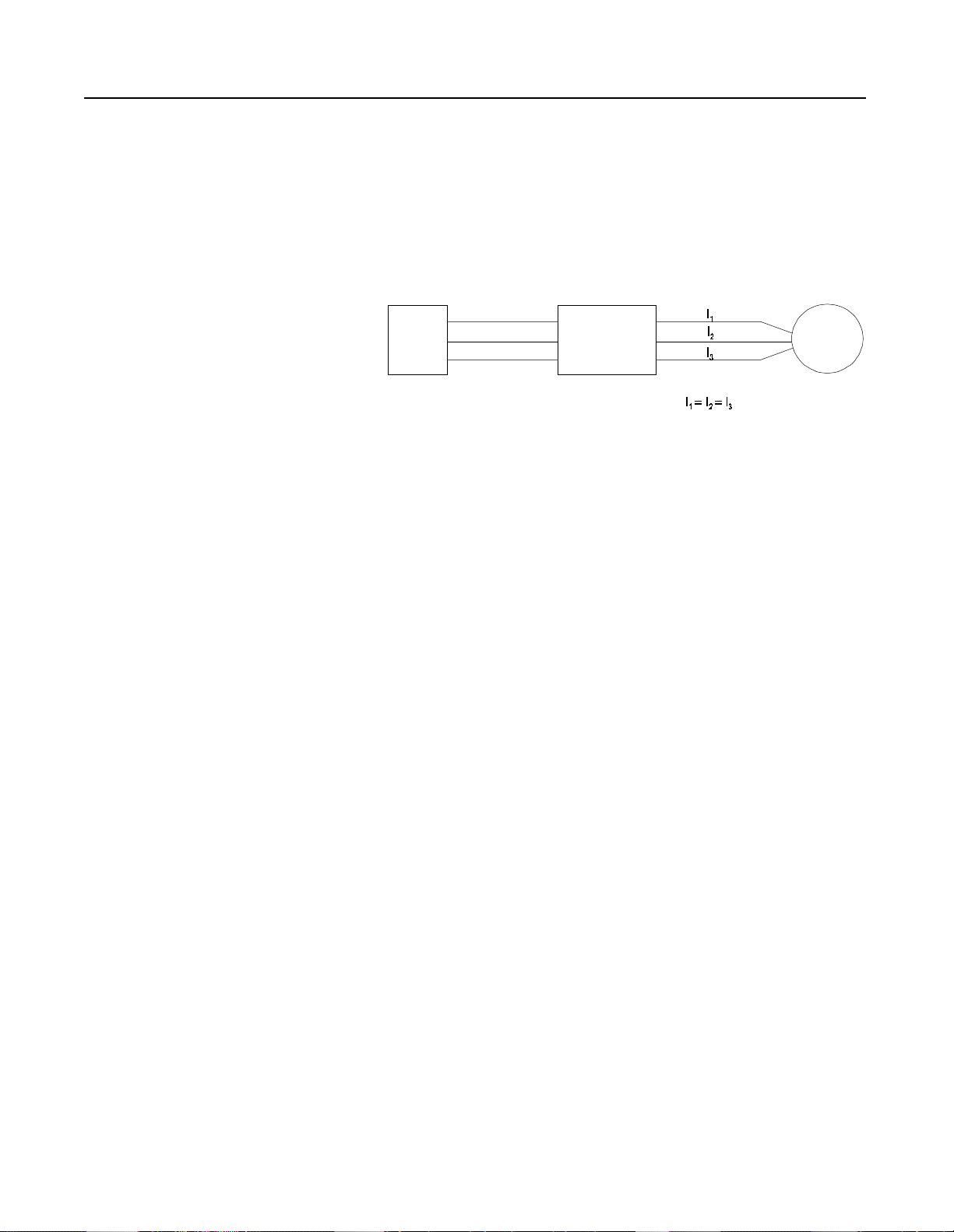
Figure 1.11 Chain Conveyor with Torque Control
Bundle Bundle
Motor
STC Starting Torque Controller
Chain
1-9
480 Volts
7.5 HP
Problem: A chain conveyor is used for transporting bundles of
paper . Due to the high sta rting torque the co nveyor motor
applies to the chain during startup, the chain was
breaking on an average of once per day. Maintenance of
the con veyor caused interruptions in the production
schedule.
Solution: The STC controller was installed to reduce the starting
torque on the motor and mechanical system. This
resulted in less downtime and higher productivity. The
STC controller was easy to retrofit due to its compact
size and feed through wiring.
Page 18
1-10
STC Starting Torque Controller
Applications (cont.)
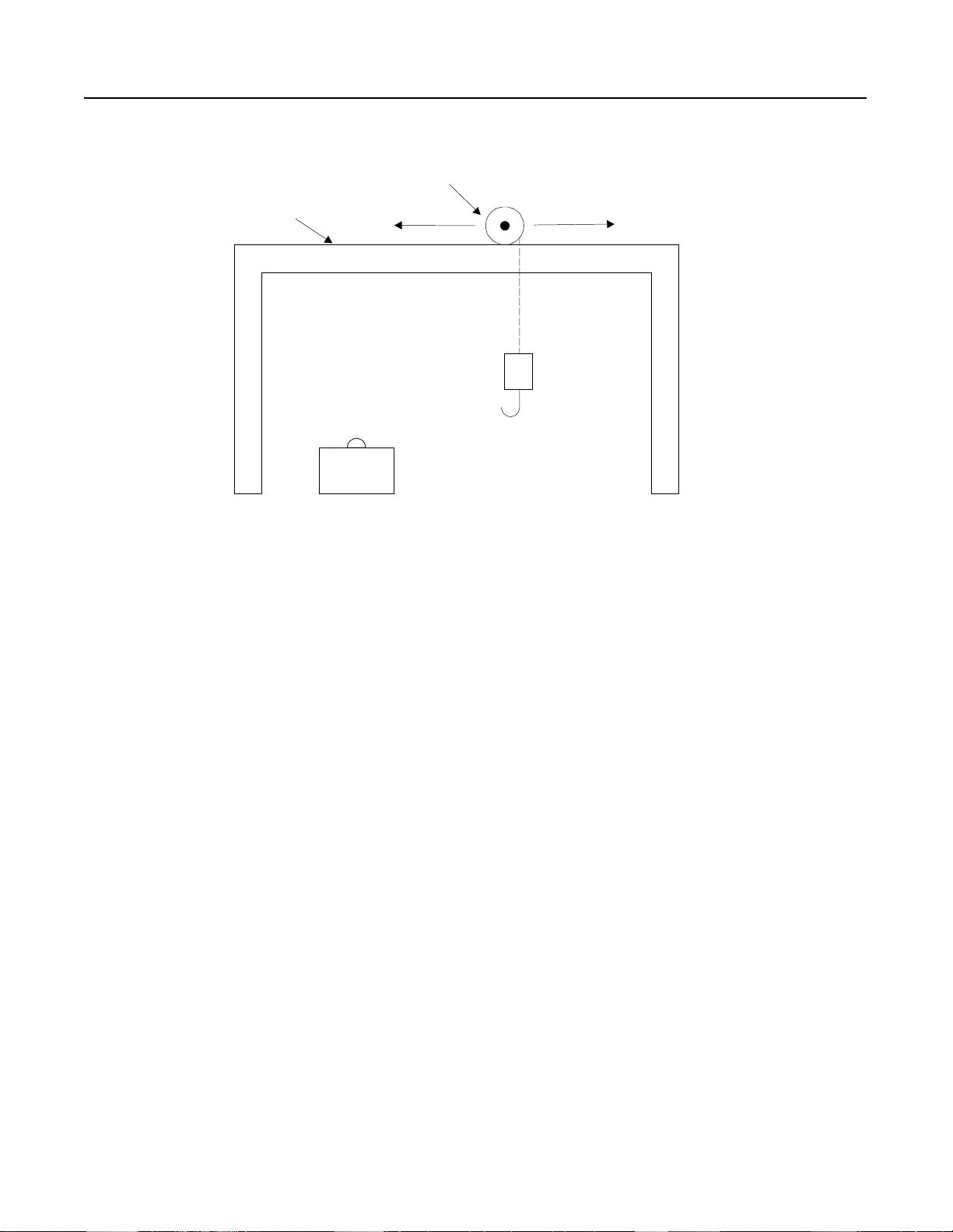
Figure 1.12 Crane with Torque Control
480 Volts
2 HP
Traverse Motor (STC Controlled)
Tra ck
Load
Problem: An overhead crane required frequent jogging due to
adjustments in the traverse (horizontal) position. An
across-the-line starter was used and this caused overshoot
or undershoot when trying to position over a load.
Solution: The STC controller was installed in the application. By
reducing the starting torque of the motor, this allowed th
crane to be positioned effectively. This meant fewer
starts were required to position the crane over the load.
This solution reduced the maintenance required as well
as improved the productivity of the crane. The STC
controller was a cost effective solution.
Page 19
STC Starting Torque Controller
Figure 1.13 Aircraft Hangar Door
1-11
480 Vol
2 Hp
Chain
Motor
Problem: A chain driven aircraft hangar door was started across-
the-line. The starting torque caused chain alignment
problems. This required frequent inspection and
maintenance.
Solution: An STC controller was installed to provide controlled
acceleration. This minimized the mechanical shock
encountered during across-the-line starting and reduced
maintenance inspection. The digital adjustments of the
STC controller were easily set and did not drift with ag
or vibration.
Page 20
Chapter 2
SMC-2 Smart Motor Controller
Description
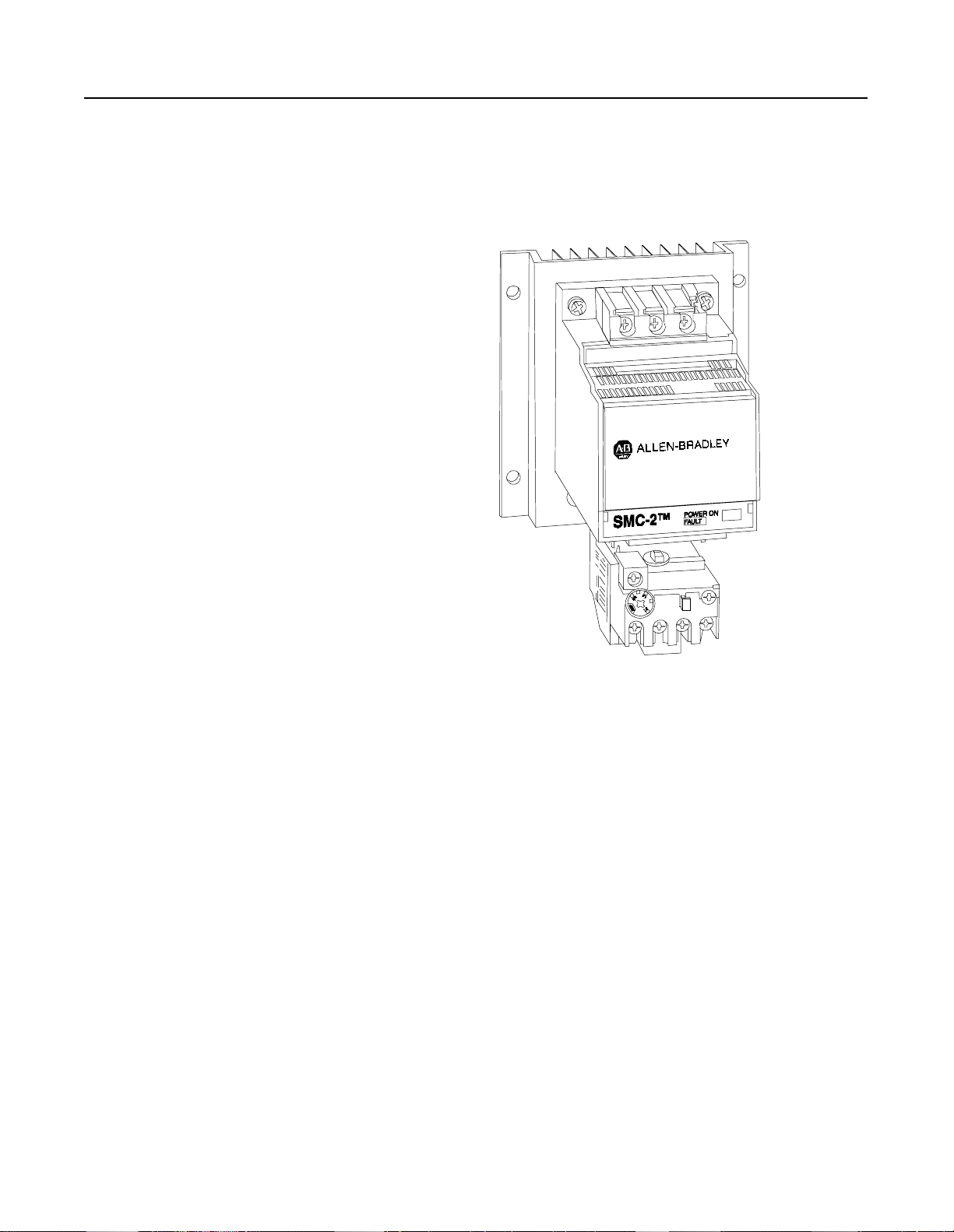
The SMC-2 Smart Motor controller is a compact, multi-functional
solid state controller used in starting standard three-phase squirrel
cage induction motors and controlling resistive loads.
The SMC-2 p ro duc t line includes c urr e nt range s from 5–9 7 Amps,
200 to 600V, 50/60 Hz., UL Listed, CSA Approved, and CE labeled.
This covers applications up to 75 horsepower.
Figure 2.1 SMC-2 Controller (5–97 Amps)
Modes of Operation The following modes of operation are standard within a single
controller:
• Soft Start
• Current Limit Start
• Full Voltage Start
The built-in energy saver feature allows the controller to conserv
energy on applications where the motor is lightly loaded or unloaded
for long periods of time.
Page 21
2-2
Start Run
Percent
Voltage
Initial
Torque
100%
Time (seconds)
SMC-2 Smart Motor Controller
Modes of Operation (cont.)
Soft Start
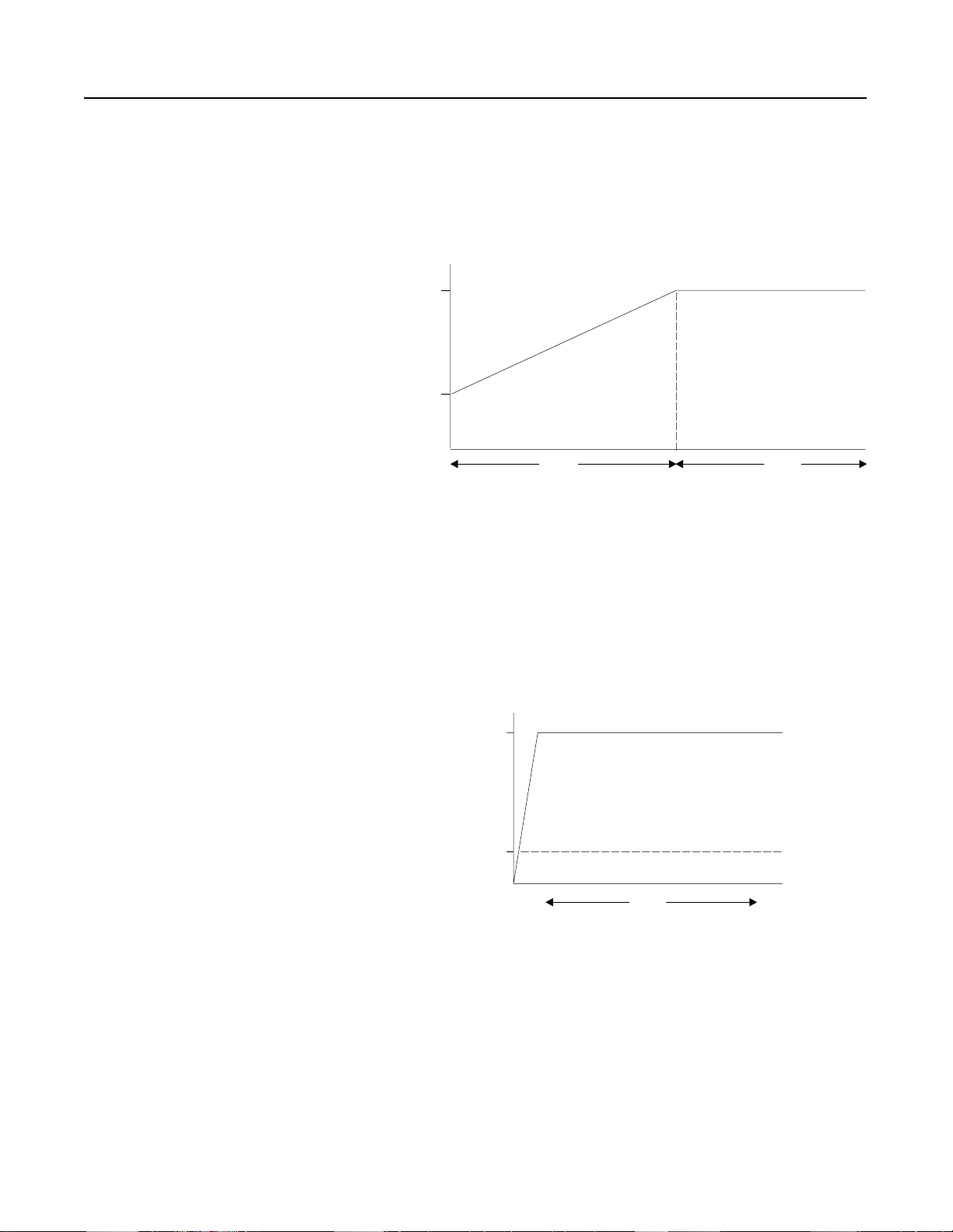
This is th e m o st co mmon me t hod of s tar t ing . The initi al torque value
is set between 0 – 70% of locked rotor torq ue. The motor voltage is
steplessly increased dur ing the acceleration ramp period, which is
adjustable from 2–30 seconds.
Figure 2.2 Soft Start
Current Limit Start
This starting mode is used when it is necessary to limit the maximum
starting c urrent. This can be adjuste d from 25 t o 550% of full load
amperes. The current limit starting time is customer set. If the motor
is not up to speed after the selected time, the motor will transition to
full voltage
Figure 2.3 Current Limit Start
550
Percent
Full Loa
Amp
25
Start
Time (seconds)
Page 22

SMC-2 Smart Motor Controller
100%
Percent
Voltage
Time (seconds)
2-3
Full Voltage Start
This mode is used in applications requiring across-the-line starting.
The ramp time is l ess than 1/10 second.
Figure 2.4 Full Voltage Start
Features
Fault Trips
There is a single red LED on the front of the SMC-2 controller for
diagnostic in di c ati o n. Wh en three -phase power is a ppl ied to the
controller, the LED will be on.
The SMC-2 controller monitors the following fault conditions:
• Shorted SCR (pre-start only)
• Phase Loss (line side and pre-start only
• Stalled Motor (when stall switch is on)
If a shorted SCR or phase loss exists, the SMC-2 controller will not
start and the LED will flash. If a stalled motor condition exists, th
controller s h uts down and flashe s the LED. In the event three-phase
input power is lost, the LED turns off.
Page 23
2-4
SMC-2 Smart Motor Controller
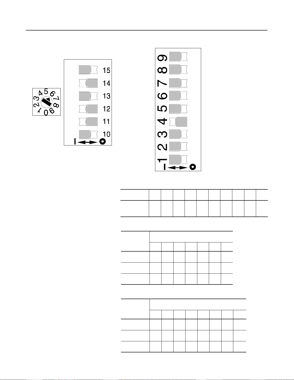
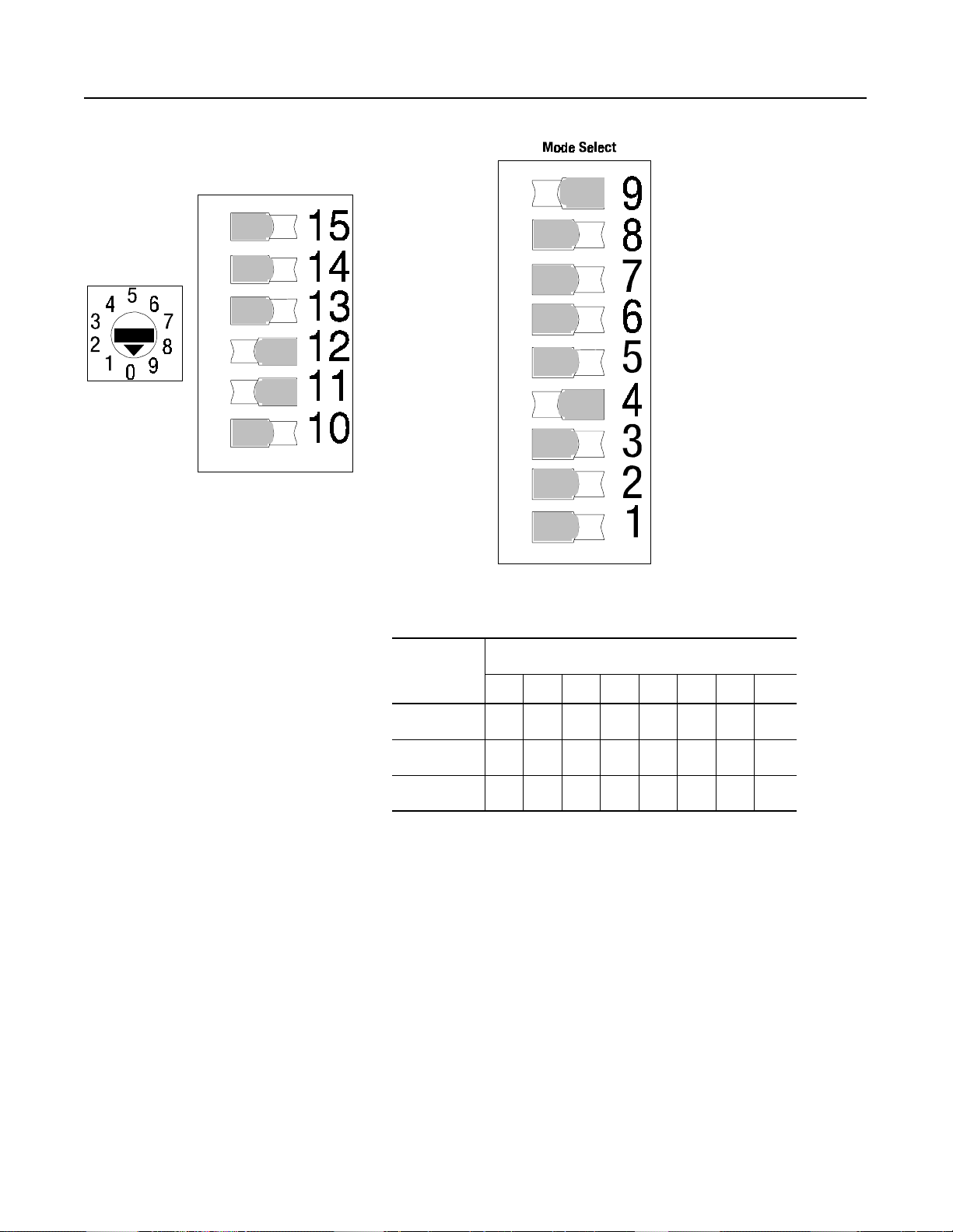
Adjustments
Figure 2.5 SMC-2 Soft Start
Mode Selec
Time Select
Starting Time
Initial Torque Leve
NOTE:
The switches shown above are for a 10 second Soft Start with a 3 0
Starting Time
Starting Time
Soft Stopping Time (Active
only with interface option)
Soft Stopping Time (Active
only with interface option)
Soft Stopping Time (Active
only with interface option)
initial torque and 25 seconds soft stop.
Full Voltage Start
Current Limit
Energy Saver Select
(ON OFF)/
50/60 H
(ON/OFF)
Auxiliary Contact (Up-to-Speed./Instant.)
(Active only with interface option)
ON Positio
Stall Select
(ON/OFF)
Soft Stop Selec
(Active only with interface option)
Must be OFF when Soft Stop not use
Soft Stop Select
(Active only with interface option)
Must be OFF when Soft Stop not use
Table 2.A Rotary Position Initial Torque Level
Position
% of Locked
Rotor Torque
0123456789
0125102030405070
Table 2.B Soft Start Time
Switch
Number
15 Off On Off On Off On Off
14 Off Off On On Off Off On
13 Off Off Off Off On On On
2 5 10 15 20 25 30
Time (seconds)
Table 2.C Soft Stop (Available only with interface option)
Switch
Number
5 101525354555110
Time (seconds)
12 Off On Off On Off On Off On
11 Off Off On On Off Off On On
10 Off Off Off Off On On On On
Page 24
SMC-2 Smart Motor Controller
Figure 2.6 SMC-2 Current Limit Selection
2-5
Time Select
Starting Time
Starting Time
Current Limit Level
NOTE:
The switches shown above are for a 15 second, 300 percent
Starting Time
Soft Stopping Time (Active
only with interface option)
Soft Stopping Time (Active
only with interface option)
Soft Stopping Time (Active
only with interface option)
current limit start with a 25 second soft stop
Table 2.D Rotary Position % Current Limit
Position
OFF Position
Current Limit
Energy Saver Select
(ON OFF)/
50/60 H
(ON/OFF)
Auxiliary Contact (Up-to-Speed./Instant.)
(Active only with interface option)
ON Positio
Stall Select
(ON/OFF)
Soft Stop Selec
(Active only with interface option)
Must be OFF when Soft Stop not used
Soft Stop Select
(Active only with interface option)
Must be OFF when Soft Stop not used
0123456789
% of Full
Load Amps
25 50 100 200 250 300 350 450 500 550
Table 2.E Current Limit Start Time
Switch
Number
15 Off On
14 Off Off
13 Off Off
Time (seconds)
15 30
Table 2.F Soft Stop (Available only with interface option)
Switch
Number
5 101525354555110
12 Off On Off On Off On Off On
11 Off Off On On Off Off On On
Time (seconds)
10 Off Off Off Off On On On On
Page 25
2-6
SMC-2 Smart Motor Controller
Adjustments (cont.)
Initial Torque Leve
Time Select
Figure 2.7 SMC-2 Full Voltage Selection
Full Voltage
Starting Time
Starting Time
Starting Time
Soft Stopping Time (Acti v
only with interface option
Soft Stopping Time (Active
only with interface option
Soft Stopping Time (Active
only with interface option
Current Limit
Energy Saver Select
(ON OFF)/
50/60 H
(ON/OFF)
Auxiliary Contact (Up-to-Speed./Instant.)
(Active only with interface option)
ON Positio
Stall Select
(ON/OFF)
Soft Stop Selec
(Active only with interface option)
Must be OFF when Soft Stop not use
Soft Stop Select
(Active only with interface option)
Must be OFF when Soft Stop not use
Table 3.G Soft Stop (Available only with interface option)
Switch
Number
12 Off On Off On Off On Off On
11 Off Off On On Off Off On On
10 Off Off Off Off Off On On On
5 101525354555110
Time (seconds)
Page 26
SMC-2 Smart Motor Controller
2-7
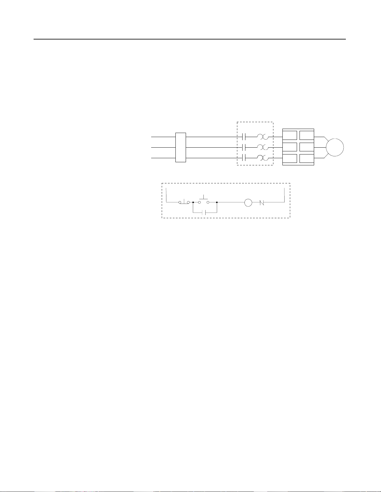
Wiring Diagram
Series Controller
The SMC-2 controller is designed to operate with an
electromechanical starter. The series mode has the following
features:
• Simplified initial installation – no need for additional wiring
• Easy retrofits – works with existing electromechanical starter
Figure 2.8 Wiring Diagram for Series Controller
M
T1/2
➀
L1/1
T2/4
L2/3
T3/6
L3/5
SMC-2
Controller
Existing Control Circuit
Power Input
3-Phase
Branch
Protection
Stop
Customer supplied.
➀
➀
➀
Start
➀
➀
M
Overload Relay
(O.L.)
➀
O.L.
M
➀
Motor
➀
Page 27
2-8
SMC-2 Smart Motor Controller
Options
Description of Interface Options
The SMC-2 controller is designed to be operated by an external
device. An optional interface is available for the SMC-2 controller.
This offers the following features:
• ON/OFF control directly to the controller through an external
device. In many applications the interface ma y e l i mi nate the
need for an additional contactor. This reduces the panel space
required.
• A configurable auxiliary contact which operates as either an
instantaneous or up-to-speed contact.
• Soft Stop. This extends stopping time to minimize load shifting
or spillage d uring stopping.
Figure 2.9 Interface Option (5–16 Amps)
This option is available as a plug-in module for the 5–16 Amp
devices. For 24–97 Amp devices, the interface is included as an
integral part of the logic design. It is not a plug-in device like th
5–16 Amp interface option.
Soft Stop Option
This function can be used in applications that require an extended
coast to rest. The voltage ramp downtime can be set from 5–110
seconds. The starting and stop ping times are independently adjusted.
The load will stop when the voltage drops to a point where the load
torque is greater than the motor torque.
Figure 2.10 Soft Start with Soft Stop
100
Percent
Voltage
Inititial
Tor que
Start Run
Soft Sto
Coast
Soft Sto
Time (Seconds)
Page 28
SMC-2 Smart Motor Controller
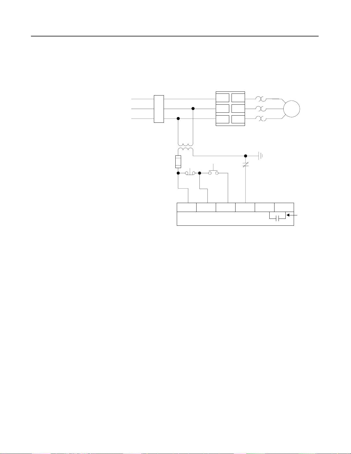
Wiring Diagram with Interface Option
Control power requirement for the interface option is 5VA at 120V
and 15VA at 240V. Auxiliary contact rating is NEMA C300, 2.5
Amps, 20–250V AC: 1 Amp, 12–30V DC.
Figure 2.11 Wiring Diagram with Interface Option
L1/1
Power Input
3-Phase
Protection
Branch
➀
➀
C.C.T.
Stop
➀ ➂
SMC-2 Controlle
➀
Start
➀
L2/3
L3/5
T1/2
T2/4
T3/6
Overload Relay
( O . L . )
O.L.
➀
➀
Motor
➀
2-9
10 20 30 40 50 60
Interface Option
Customer supplied
➀
Maximum fuse size 10A, 250V.
➁
For two wire control, remove stop/start push buttons and
➂
connect two wire device between terminals 10 and 30
Auxiliar
Contact
Page 29
2-10
SMC-2 Smart Motor Controller
Options (cont.)
Overload Relay Option
To save additional panel space, IEC overload relays may be mounted
directly to the 5, 9, and 16 Amp SMC-2 controllers.
Figure 2.12 SMC-2 Controller with Bulletin 193 Overload Relay (5–16 Amps)
Applications In this section a few of many applications are described, as well as
why the particular control method was selected. For example,
tumbler drum is described using a soft start feature. We will then
“build” upon this application to describe how the SMC-2 controller
options can be used to improve the tumbler drum performance and
productivity.
Illustrations are included to he l p identify the particular application.
Motor ratings are specified but this may vary in other typical
applications.
Page 30
SMC-2 Smart Motor Controller
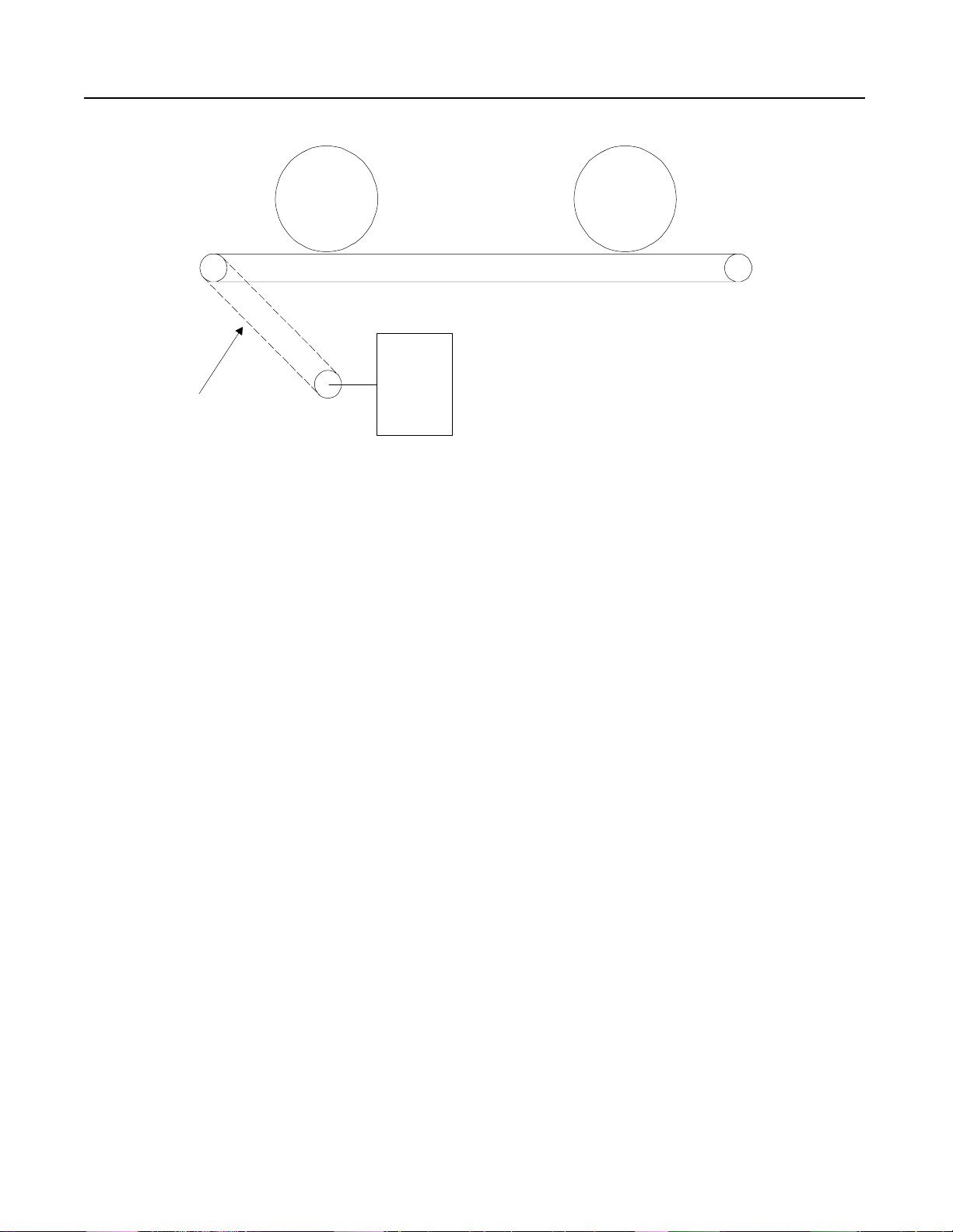
Figure 2.13 Conveyor with Soft Start
2-11
480 Vol
7.5 HP
LOG
Motor
Chain
LOG
Problem: A conveyor is used to transport logs. The drive chain was
breaking due to uncontrolled start-up. This caused
interruptions in the production schedule and lost
productivity. Panel space was very limited.
Solution: Due to its compact design, the SMC-2 controller was
easily installed in the space vacated by the previous
starter. A 10-second soft start was selected. This
reduced the starting torque and the shock to the
mechanical sy ste m.
Page 31

2-12
SMC-2 Smart Motor Controller
Applications (cont.)
Figure 2.14 Tumbler with Soft Start
480 Volts
50 HP
Loading Door
Tumbler D rum
Motor
Drive Chain
Problem: A tumbler used in a na il finishing process was breaking
the drive chain due to the uncontrolled acceleration from
the across-the-line start. In addition, a reversing starte
was needed to position the drum to the top position for
loading the product. Due to lack of co ntrolled
acceleration, numerous jogs were used to position the
drum. The stopping time was not a con cer n in this
application. In addition, single phasing of the motor was
a frequent problem, causing premature motor failure.
Solution: The SMC-2 controller was installed after the reversing
contactor to control the starting torque of the motor. This
prevented the snapping of the drive chain on the start up
which increased the life of the chain and reduced th
downtime on the tumbler. In addition, the SMC-2
controller made it easier to jog the drum into position for
loading and unloading. (The SMC-2 controller slowed
the acceleration rate to prevent overshoot.) This helped
improve the prod uctivity of the l oad ing and unloading
process. In addition, the SMC-2 controller could quickly
detect the phase failure during starting. The controller
would prevent starting until the line had been corrected.
This added additional s tandard protection to the motor
and system.
Page 32
SMC-2 Smart Motor Controller
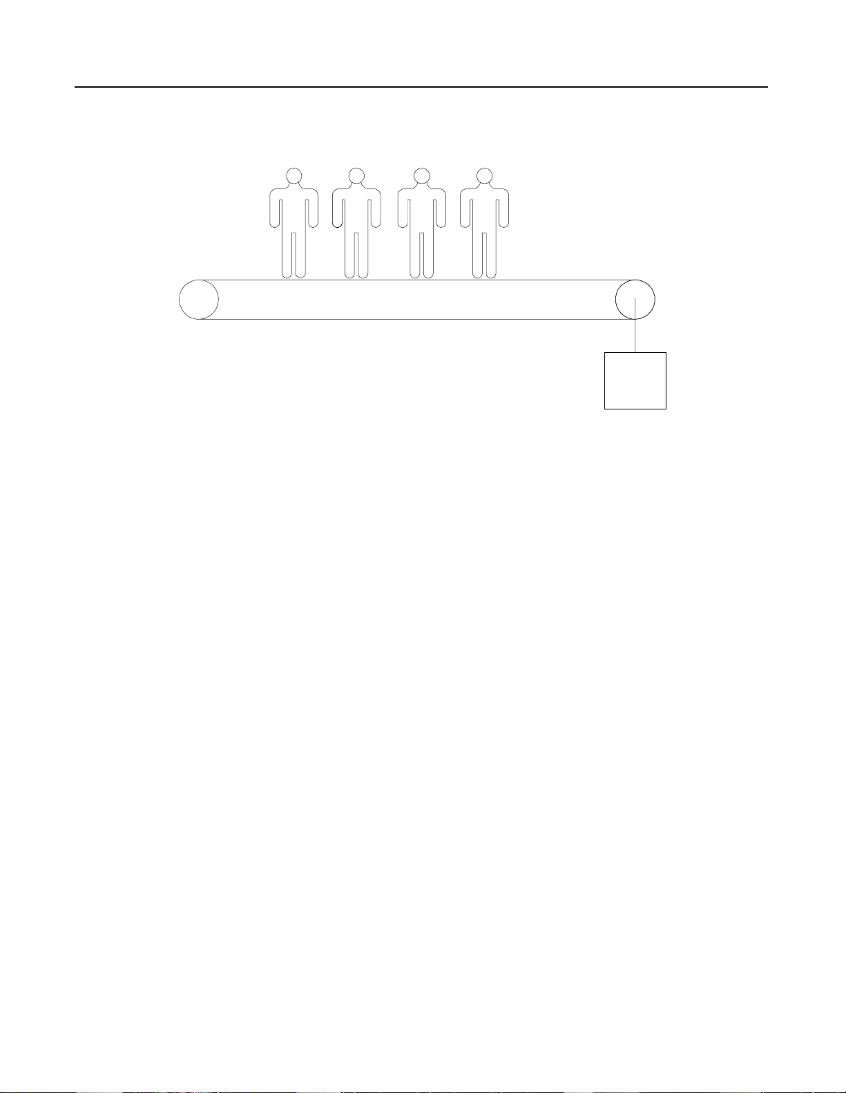
Figure 2.15 Power Walk with Soft Start and Soft Stop Option
240 Volts
15 HP
Motor
2-13
Problem: A power walk at an a ir po rt req u ire d a soft star t to prevent
damage to the drive chain gearbox on start-up. A soft
stop was also required in case the power walk would b
shut off while people were still on the belt. There would
be multiple units at the site, and a controller that could be
quickly installed and adjusted was required.
Solution: The SMC-2 controller with the Interface option was
designed into the system. A 10-second soft start with the
Energy Saver enabled was selected. A 10-second soft
stop was also selected. This allowed the power walk to
have a controlled start and stop. D ur ing p eriods where
the walk was unloaded, the SMC-2 controller Energy
Saver reduced the voltage to the motor, minimizing the
magnetic losses of the motor.
Page 33

2-14
SMC-2 Smart Motor Controller
Applications (cont.)
Pallet
Figure 2.16 Towline Conveyor with Soft Start and Soft Stop Option
480 Volts
15 HP
Load Load
Gearbox
Motor
Problem: A towline conveyor at the en d of a production line had
frequent damage to the gearbox due to the starting torque
from acr oss -the -li ne starting of the motor. There were
frequent spills on both starting and stopping of the
conveyor system.
Solution: The SMC-2 controller with the Interface option was
installed. Starting and stopping times of 15 seconds were
selected. The reduced torque starting prevented shock to
the gearbox and kept the load from shifting on st art-up.
The soft stop prevented the load shifts while stopping.
The SMC-2 c on t ro ller met the application requirements
and was a cost effective solution.
Page 34

SMC-2 Smart Motor Controller
Figure 2.17 Bottle Filler with Soft Start and Soft Stop Option
480 Volts
1 HP
Filler
2-15
Problem: A bottle filler line had product spillage upon starting and
stopping. An across-the-line starter w as used to start th
motor. In addition, the application required an auxiliary
contact that would energize when the motor was up to
speed.
Solution: The SMC-2 controller was installed and set for a 10-
second soft start with a 20-second soft stop. This
controlled the starting torque a n d prevented the sudden
start that w ould cause t h e bottles to spi ll. The soft stop
extended the stopping time eliminating load shift while
stopping. T h e auxiliar y conta c t was configured to
change state when the motor was up to speed.
Page 35

2-16
SMC-2 Smart Motor Controller
Applications (cont.)
Motor
Figure 2.18 Grinder with Soft Start
575 Volts
20 HP
Grinding
Wheel
Gearbox
Problem: Due to the high starti ng torque developed from starting
the motor across-the-line, the gears driving a grinding
wheel were frequently damaged. T his resulted in
unscheduled downtime for repair. T his application
required a rugged device because vibration at the control
panel was a problem.
Solution: The SMC-2 controller was installed and set for a
20-second acceler ation time. This reduced the starting
torque and the downtime for repairs on the grinder. In
addition, the benefit of the Energy Saver was realized
when the motor was running lightly loaded. The SMC-2
controller meets the same shock and vibration
requirements as electromechanical devices, therefore it
met the durability requirements.
Page 36

SMC-2 Smart Motor Controller
Figure 2.19 Passenger Elevator
2-17
Problem: A passenger e l evator i n a parking structure r equ ired a soft
start to el imin ate the jolt w hi ch occurred during an
across-the-line start. Due to the size of the en closure, the
soft starter must fit in the space vacated by the
electromechanical motor starter.
Solution: An SMC-2 c o nt rolle r with the Int erfa ce o p t ion was
installed. The starting time was set for 10 seconds. This
reduced the starting torque and eliminated the jolt during
the start. The Interface option allowed all control wiring
to be connected directly to the SMC-2 controller, thereby
eliminating the need for the electromechanical motor
starter. The small size of the SMC-2 controller allowed it
to fit easily into the space vacated by th
electromechanical motor starter.
Page 37

2-18
SMC-2 Smart Motor Controller
Page 38

Chapter 3
SMC Dialog Plus Smart Motor Controller
Description
When the Smart Motor Controller (SMC) was first introd uced in
1986, its modular design, digital set-up, and microprocessor control
set the standard for soft starters. Since its launch in 1989, the SMC
PLUS controller has been in a class by itself, providing unmatched
performance with innovative starting and stopping options. Now, the
SMC Dialog Plus controller achieves a higher level of
sophistication with greatly enhanced protection, expanded
diagnostics, a nd t he a b ility to log the motor’s operation (amps, kW,
and power factor), as well as the option to “dialog” with various
network protocols.
While the SMC Dialog Plus controller incorporates many new
features into its design, it remai ns easy to set-up and operate. You can
make use of as few or as many of the features as your application
requires.
The SMC Dialog Plus controller is a compact, modular, multifunctional solid-state controller used in starting three-phase squirrel
cage induction motors and controlling resistive loads. The SMC
Dialog Plus product line includes current ratings from 24 to 1000
Amps, 200 to 600V, 50/60Hz. This covers applications up to 1000
horsepower. The SMC Dialog Plus c on troller meets applicab l
standards and requirements.
Figure 3.1 SMC Dialog Plus Controller (24–1000 Amps)
Page 39

3-2
SMC Dialog Plus Smart Motor Controller
Starting Methods
The following starting methods are standard within the controller:
• Soft Start with Selectable Kickstart
• Current Limit Start
• Dual Ramp Start
• Full Voltage Start
Optional fea tu res include:
• Soft Stop
• Pump Control
• Preset Slow Speed
•SMB Smart Motor Brake
• Accu-Stop/Slow Speed with Braking
Soft Start with Selectable Kickstart
This meth od h a s the m o st general app li c a tion. The motor is given an
initial torque setting, which is user adjustable from 0 to 90% of
locked rotor torque. From the initial torque level, the output voltag
to the motor is steplessly increased during the acceleration ramp time,
which is user adjustable from 0 to 30 seconds. If, during the voltag
ramp operation, the SMC Dialog Plus controller senses that the moto
has reached an up-to-speed condition, the output voltage will
automatically switch to full voltage.
The kickstart feature provides a boost at start-up to break away loads
that may require a pulse of high torque to get started. It is intended to
provide a current pulse of 550% of full load current and is user
adjustable from 0.0 to 2.0 seconds.
Figure 3.2 Soft Start with Selectable Kickstart
Percent
Voltage
Kickstart
100%
Initial
Torque
Start Run
Time (seconds)
Page 40

SMC Dialog Plus Smart Motor Controller
Percent
Voltage
Initial
Torque #1
100
Start #1 Run #1
Ramp #2
Ramp #1
Start #2
Time (seconds)
Run #2
Initial
Torque #2
3-3
Current Limit Start
This starting method provides a fixed reduced voltage start and is
used when it is necessary to limit the maximum starting current. Th
starting current is user adjustable from 50 to 600% of full load
amperes. The current limit starting time is user adjusta ble from 0 to
30 seconds.
Figure 3.3 Current Limit Start
600%
Percent
Full Load
Current
50%
Start
Time (seconds)
Dual Ramp Start
This starting method is useful on applications with varying loads and
varying starting torque requirements. Dual Ramp Start offers the user
the ability to select between two separate Soft Start profiles with
separately adjustable ramp times and initial torque settings.
Figure 3.4 Dual Ramp Start
Page 41

3-4
10 0
Percent
Voltage
Time (seconds)
SMC Dialog Plus Smart Motor Controller
Starting Methods (cont.)
Full Voltage Start
This meth od is used in appli c ations requ iring across-the- l ine starting.
The SMC Dialog Plus controller perf orms like a solid-state contactor.
Full inrush current and locked rotor torque are realized.
Figure 3.5 Full Voltage Start
Features
LCD Display
A two line, sixteen character b acklit LCD display provides parameter
definition with straightforward text so that controller set-up may be
accomplished without a reference manual. Parameters are arranged
in an organized four level menu structure for ease of programming
and fast access to parameters.
Keypad Programming
Programming of param et ers is accomplished through a five button
keypad on the fro nt of the SMC Di alog P lu s controller. The five
buttons include up and down arro ws, an Enter button, a Select button,
and an Escape button. The user needs only to enter the correct
sequence of keystrokes for programming the SMC Dialog Plus
controller.
Figure 3.6 LCD Display with Keypa
Page 42

SMC Dialog Plus Smart Motor Controller
3-5
Electronic Overload
The SMC Dialog Plus controller meets applicable requirements as
motor overload protective device. Overload protection is
2t
accomplished electronically through an I
algorithm.
The overload is programmable, providing the user with flexibility.
The overload trip class is selectable for class 10, 15, 20, or 30
protection. The tr i p current is set by entering th e motor’s full load
current rating and the service factor.
Thermal memory i s i n cl u de d t o a ccurately model motor operating
temperature. Ambient insensitivity is inherent in the electronic
design of the o v er lo ad .
Note: The current sensing capability of the SMC Dialog Plus
controller i s d i sa b le d du ring b y pass operat ion. The Bulletin
825 Converter Module is required to provide current
feedback in these applications.
Built-in Communication Port
A serial interface port is furnished as standard with the SMC Dialog
Plus controller. This communication port allows for connection to a
Bulletin 1201 Hu m an Interface Module. It a l so allows fo r a variety of
other communications, including Allen-Bradley’s Remote I/O, DH485, RS 232/422/485-DF1, and DeviceNet network through the
connection to the Bulletin 1203 communication modules.
Page 43

3-6
Stall
60 0
Percent
Full
Load
Current
Time (seconds)
Programmed Start Time
100%
Running Jam
Percent
Full
Load
Current
Time (seconds)
User Programmed Trip Level
SMC Dialog Plus Smart Motor Controller
Features (cont.)
Stall Protection and Jam Detection
Motors can experience locked rotor currents and develop maximum
torque in the event of a stall (during start) or a jam (after full speed is
reached). These conditions can result in winding insulation
breakdown or mechanical damage to the connected load.
The SMC Dialog Plus controller prov ides both sta ll and jam detection
for enhanced motor and system protection. Stall protection allows the
user to program a maximum stall time of up to 10 seconds. Jam
detection allows the user to determine the jam level as a percentage o
the motor’s full load current rating, and a trip delay time of up to 10
seconds.
Note: The stall trip delay time is in addition to the programmed
start time.
Figure 3.7 Stall Protection
Figure 3.8 Jam Detection
Page 44
SMC Dialog Plus Smart Motor Controller
SMC Dialog Plus
Supply
Voltage
501V
480V
462V
Motor
3-7
Phase Rebalance
As little a s 4% supply vo l ta ge un balanc e ca n resul t in a 20% current
unbalance a n d a 25% in cr e ase in motor tem p era t u re, possibly
triggering a premature failure of the motor. The SMC Dialog Plus
controller continuously monitors the incoming three-phase line
voltage balance and adjusts the output voltage automatically to
balance the three-phase currents drawn by the motor.
Figure 3.9 Phase Rebalance
Notes: (1) Phase Rebalance is not active during bypass operation.
(2) Phase rebalance requires the use of the converter modul
(Bulletin 825) and fanning strip (Cat. No. 150-NFS).
Metering
The SMC Dialog Plus controller contains several power monitoring
parameters as standard. These parameters include:
• Three-phase Current • Three-phase Voltage
• Power in kW • Power Usage in kWH
• Power Factor • Elapsed Time
• Motor Thermal Capacity Usage
Fault Indication
The SMC Dialog Plus controller monitors both the pre-start and
running modes. If the controller senses a fault, the SMC Dialog Plus
controller shuts down t h e motor and displays the appropriate fault
condition in the LCD display. The controller monitors the following
conditions:
• Open Gate • L i ne Fault
• Undervoltage • Underload
• Overvoltage • Excessive Starts/Hour
• Voltage Unbalance • Overtemperature
• Phase Reversal • Stall
• Power Loss • Jam
• Overload • System
Any fault condition will ca u se t he auxiliary co ntacts to change state
and the hold- in circuit to release.
Page 45
3-8
SMC Dialog Plus Smart Motor Controller
Features (cont.)
Auxiliary Contacts
Three hard contacts are provided as standard with the SMC Dialog
Plus controller. The first two contacts are programmable for Normal/
Up-to-sp ee d . The third con tact is program mable for Normal/Fault.
Energy Saver
The built-in Energy Saver feature is integral to the SMC Dialog Plus
controller and may be applied to applications whe re the motor is
lightly loade d or unloaded for long periods of time. With the Energy
Saver feature enabled, the SMC Dialog Plus controller continuously
monitors the l oading of the motor wi th its internal feedback circuitry.
Because the output voltage is SCR control led, moto r power losses can
be reduced by decreasing the motor terminal voltage.
Note: The Energy Saver feature is not available when a bypass
contactor is used.
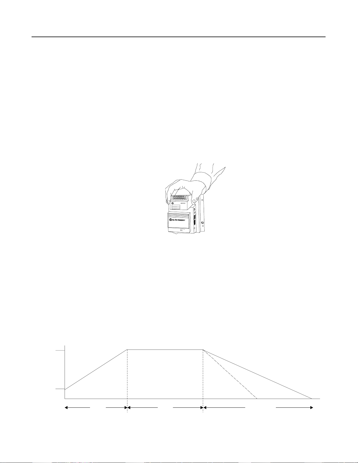
Modular Design
The SMC Dialog Plus controller packaging is designed for industrial
environments. The mod u lar i ty of co n tr ol and power modules featur
plug-in functionality. There are no gate wires to remove and no
soldering is required. Common control modules reduce inventory
requirements.
Figure 3.10 Exploded View of the 24 Amp SMC Dialog Plus Controller
Page 46

SMC Dialog Plus Smart Motor Controller
3-9
Control Terminal Description
The SMC Dialog Plus controller contains 20 control terminals on the
front of the controller. These control terminals are described below.
See Figure 3.11.
Power Supply Board
Terminal Number Description
11 Control Power Input
12 Control Power Common
13 Controller Enable Input
14 Logic Ground
15 Dual Ramp/Option Input
16 Start Input
17 Stop Input
18 Auxiliary Relay Common
19 N.O. Auxiliary Contact 1 (Normal/Up-to-speed)
20 N.C. Auxiliary Contact 2 (Normal/Up-to-speed)
Logic Board
Terminal Number Description
21 Not Used
22 Not Used
23 Not Used
24 Not Used
25 Common (Converter Module)
26 Phase A Input (Converter Module)
27 Phase B Input (Converter Module)
28 Phase C Input (Converter Module)
29 N.O./N.C. Auxiliary Contact 3 (Normal/Fault)
30 N.O./N.C. Auxiliary Contact 3 (Normal/Fault)
Figure 3.11 SMC Dialog Plus Controller Control Terminals
Page 47

3-10
SMC Dialog Plus Smart Motor Controller
Adjustments
Soft Start without Options
The following parameters are specifically used to provide and adjust
the voltage ramp supplied to the motor
Para mete r Range
Starting Mode
This must be programmed for “Soft Start.”
Ramp Time #1
This sets the time period during which the
controller will ramp the output voltage.
Initial Torque #1
The initial output voltage level for the voltage
ramp is established and adjusted with this
parameter.
Kickstart Time
A boost of 550% of full load current is provided
to the motor for the programmed time period.
Stall Delay
Allows the user to program the stall protection
delay time. The delay time begins after the
start time has timed out.
Soft Start, Current Limit
0 to 30 seconds
0 to 90% of locked rotor torque
0.0 to 2.0 seconds
0 to 10 seconds
Energy Saver
The Energy Saver feature monitors the motor
load, phasing back the voltage output to the
motor when the motor is lightly loaded or
unloaded for an extended period of time.
Aux Contacts 1&2
Two form C contacts are provided as standard
with the SMC Dialog Plus controller. These
contacts are located at terminals 18, 19, and
20. Aux Contacts 1&2 allows the user to
configure the operation of the contacts.
Aux Contact 3
A third auxiliary contact is provided between
terminals 29 and 30. Aux Contact 3 allows the
user to program the operation of the contact.
Contact 3 Config
This parameter provides the user with the
ability to program the “powered-up” state of
the third auxiliary contact.
Parameter Mgmt
The newly programmed parameters values can
be saved to memory, or the factory default
parameter values can be recalled.
Off, On
Normal, Up-to-speed
Normal, Fault
N.O., N.C.
Ready, Default Init., Recll Frm EE,
Store In EE
Page 48

SMC Dialog Plus Smart Motor Controller
3-11
Current Limit Start without Options
To apply a fixed reduced voltage o utput to the motor, the following
parameters are provided for user adjustment.
Para mete r Range
Starting Mode
This must be programmed for “Current Limit.”
Ramp Time #1
This sets the time period during which the
controller will hold the fixed reduced voltage
output before switching to full voltage.
Current Limit Level
This provides adjustability for the reduce
voltage output level to the motor.
Kickstart Time
A boost of 550% of full load current is provided
to the motor for the programmed time period.
Stall Delay
Allows the user to program the stall protection
delay time. The delay time begins after the
start time has timed out.
Energy Saver
The Energy Saver feature monitors the motor
load, phasing back the voltage output to the
motor when the motor is lightly loaded or
unloaded for an extended period of time.
Aux Contacts 1&2
Two form C contacts are provided as standard
with the SMC Dialog Plus controller. These
contacts are located at terminals 18, 19, and
20. Aux Contacts 1&2 allows the user to
configure the operation of the contacts.
Soft Start, Current Limit
0 to 30 seconds
50 to 600% of full load current
0.0 to 2.0 seconds
0 to 10 seconds
Off, On
Normal, Up-to-speed
Aux Contact 3
A third auxiliary contact is provided between
terminals 29 and 30. Aux Contact 3 allows the
user to program the operation of the contact.
Contact 3 Config
This parameter provides the user with the
ability to program the “powered-up” state of
the third auxiliary contact.
Parameter Mgmt
The newly programmed parameters values can
be saved to memory, or the factory default
parameter values can be recalled.
Normal, Fault
N.O., N.C.
Ready, Default Init., Recll Frm EE,
Store In EE
Page 49

3-12
SMC Dialog Plus Smart Motor Controller
Adjustments (cont.)
Dual Ramp Start without Options
The SMC Dialog Plus controller provides the user with the ability to
select between two soft start profiles. To obtain Dual Ramp Start
control, the following parameters are available in the “Advanced
Setup” progr ammi ng mode.
Note: The Dual Ramp Start feature is only a va ila ble with the
standard control module.
Parameter Range
Advanced Setup
The user must select the “Advanced Setup”
programming mode in order to obtain access to
the Dual Ramp Start parameters
Starting Mode
This must be programmed for “Soft Start.”
Dual Ramp
This allows the user to choose between two
soft start profiles defined by:
Ramp Time #1 and Initial Torque #1
Ramp Time #2 and Initial Torque #2
When the Dual Ramp feature is selected, the
ramp time/initial torque combination is
determined by a hard contact to input terminal
15. A low input signal to terminal 15 signifies
that ramp time/initial torque #1 are selected. A
high input signal to terminal 15 signifies that
ramp time/initial torque #2 are selected.
—
Soft Start, Current Limit
No, Yes
Ramp Time #1
This determines the time period in which the
controller will ramp the output voltage to the
motor for the first soft start setup.
Initial Torque #1
The initial reduced voltage output level for the
first soft start setup is established and adjusted
with this parameter.
Ramp Time #2
This determines the time period in which the
controller will ramp the output voltage to the
motor for the second soft start setup.
Initial Torque #2
The initial reduced voltage output level for the
second soft start setup is established and
adjusted with this parameter.
Kickstart Time
A boost of 550% of full load current is provided
to the motor for the programmed time period.
0 to 30 seconds
0 to 90 % of locked rotor torque
0 to 30 seconds
0 to 90 % of locked rotor torque
0.0 to 2.0 seconds
Page 50

SMC Dialog Plus Smart Motor Controller
Dual Ramp Start without Options (cont.)
Parameter Range
Stall Delay
Allows the user to program the stall protection
delay time. The delay time begins after the
start time has timed out.
Energy Saver
The Energy Saver feature monitors the motor
load, phasing back the voltage output to the
motor when the motor is lightly loaded or
unloaded for an extended period of time.
Aux Contacts 1&2
Two form C contacts are provided as standard
with the SMC Dialog Plus controller. These
contacts are located at terminals 18, 19, and
20. Aux Contacts 1&2 allows the user to
configure the operation of the contacts.
Aux Contact 3
A third auxiliary contact is provided between
terminals 29 and 30. Aux Contact 3 allows the
user to program the operation of the contact.
3-13
0 to 10 seconds
Off, On
Normal, Up-to-speed
Normal, Fault
Contact 3 Config
This parameter provides the user with the
ability to program the “powered-up” state of
the third auxiliary contact.
Parameter Mgmt
The newly programmed parameters values can
be saved to memory, or the factory default
parameter values can be recalled.
N.O., N.C.
Ready, Default Init., Recll Frm EE,
Store In EE
Page 51

3-14
SMC Dialog Plus Smart Motor Controller
Adjustments (cont.)
Full Voltage Start without Options
The SMC Dialog Plus controller may be programmed to provid
full voltage start in whi ch t he o u tput vol ta g e to th e mot or re aches full
voltage in 1/4 second.
Parameter Range
Start Mode
This must be programmed for “Soft Start.”
Ramp Time #1
This must be programmed for “0” seconds.
Initial Torque #1
This must be programmed for 90% of locked
rotor torque.
Kickstart Time
This must be programmed for “0” seconds.
Stall Delay
Allows the user to program the stall protection
delay time. The delay time begins after the
start time has timed out.
Energy Saver
The Energy Saver feature monitors the motor
load, phasing back the voltage output to the
motor when the motor is lightly loaded or
unloaded for an extended period of time.
Soft Start, Current Limit
0 to 30 seconds
0 to 90% of locked rotor torque
0.0 to 2.0 seconds
0 to 10 seconds
Off, On
Aux Contacts 1&2
Two form C contacts are provided as standard
with the SMC Dialog Plus controller. These
contacts are located at terminals 18, 19, and
20. Aux Contacts 1&2 allows the user to
configure the operation of the contacts.
Aux Contact 3
A third auxiliary contact is provided between
terminals 29 and 30. Aux Contact 3 allows the
user to program the operation of the contact.
Contact 3 Config
This parameter provides the user with the
ability to program the “powered-up” state of
the third auxiliary contact.
Parameter Mgmt
The newly programmed parameters values can
be saved to memory, or the factory default
parameter values can be recalled.
Normal, Up-to-speed
Normal, Fault
N.O., N.C.
Ready, Default Init., Recll Frm EE,
Store In EE
Page 52

SMC Dialog Plus Smart Motor Controller
3-15
Typical Wiring Diagrams (without options)
Figure 3.12 Typical Wiring Diagram for Standard Controller
L1/1
T1/2
3-Phase
Input Power
Protection
Fast-acting
➀
Branch
➀
➀
➁
11 12 13 14 15 16 17 18 19 20
SCR Fuses
(optional)
➀
➀
Stop
➀
Start
➀
L2/3
L3/5
T2/4
T3/6
M
➀
21 22 23 24 25 26 27 28 29 30
Customer supplied.
①
Refer to the controller nameplate to verify the rating of the control power input voltage.
②
Internal
Auxiliary
Contacts
Page 53

3-16
SMC Dialog Plus Smart Motor Controller
Typical Wiring Diagrams
(without options)
Figure 3.13 Typical Wiring Diagram for Dual Ramp Applications
Control Power
Ramp 1 ➀Ramp 2
11 12 13 14 15 16 17 18 19 20
➁
Start
SMC Dialog Plus
Control Terminals
Stop
➀
➀
Internal
Auxiliary
Contacts
21 22 23 24 25 26 27 28 29 30
Customer supplied.
①
Refer to the controller nameplate to verify the rating of the control power input voltage.
②
Note: The Dual Ramp feature is only available with the standard control module.
Page 54

SMC Dialog Plus Smart Motor Controller
3-17
Figure 3.14 Typical Wiring Diagram for Start-Stop Control via the SCANport
Control Power
➁
➂
11 12 13 14 15 16 17 18 19 20
21 22 23 24 25 26 27 28 29 30
Customer supplied.
①
Refer to the controller nameplate to verify the rating of the control power input voltage.
②
If Soft Stop, Pump Control, or SMB Smart Motor option is installed, place additional jumper to
③
terminal 15.
Page 55

3-18
SMC Dialog Plus Smart Motor Controller
Typical Wiring Diagrams
(without options) (cont.)
Figure 3.15 Typical Wiring Diagram for Retrofit Applications
L1/1
3-Phase
Input Power
Branch
Protection
➀
Fast-acting
SCR Fuses
(Optional)
➀
➀
➀
Starter
OL
Existing Motor
L2/3
L3/5
T1/2
T2/4
T3/6
M
Start
Stop
➀
➀
M
➀
➀
M
➁
11 12 13 14 15 16 17 18 19 20
21 22 23 24 25 26 27 28 29 30
Customer supplied.
①
Refer to the controller nameplate to verify the rating of the control power input voltage.
②
Page 56

SMC Dialog Plus Smart Motor Controller
Start Run Soft Stop
Coast-to-rest
Soft
Stop
Kickstart
Initial
Torque
100%
Percent
Voltage
Time (seconds)
3-19
Control Options
The SMC Dialog Plus controller offers a variety of unique control
options that provide enhanced motor starting and stopping
capabilities. Please note that the options are mutually exclusive and
must be specified at the time of order entry.
• Soft Stop
• Pump Control
• Preset Slow Speed
•SMB Smart Motor Braking
• Accu-Stop/Slow Speed with Braking
Soft Stop Option
The Soft Stop option can be used in applications requiring an
extended coast-to-rest. The voltage ramp down time is use
adjustable from 0 to 60 seconds. The Soft Stop time is adjusted
independently from the start time. The load will stop when the
voltage drops to a point where the load torque is greate r th an th
motor torque.
Figure 3.16 Soft Stop Option
ATTENTION: Soft Stop is not intended to be used as
an emergency stop. Refer to the applicable standards for
!
emergency stop requirements
Page 57

3-20
SMC Dialog Plus Smart Motor Controller
Control Options (cont.)
Soft Stop Option (cont.)
Figure 3.17 Typical Wiring Diagram for Soft Stop Option
Control Power
11 12 13 14 15 16 17 18 19 20
➁
Soft Stop
Stop
➀
➀
Start
➀
21 22 23 24 25 26 27 28 29 30
Customer supplied.
①
Refer to the controller nameplate to verify the rating of the control power input voltage.
②
Page 58

SMC Dialog Plus Smart Motor Controller
Programming - Soft Start with Soft Stop Option
The basic parameter set-up for Soft Start selection with Soft Stop
option follows:
Para mete r Range
3-21
SMC Option
“Soft Start” will be displayed.
Starting Mode
Allows the user to program the SMC Dialog Plus
controller for the type of starting that best fits
the application.
Ramp Time
This sets the time period during which the
controller will ramp the output voltage.
Initial Torque
The initial reduced voltage output level for the
voltage ramp is established and adjusted with
this parameter.
Kickstart Time
A boost of 550% of full load current is provided
to the motor for the programmed time period.
Stall Delay
Allows the user to program the stall protection
delay time. The delay time begins after the
start time has timed out.
Energy Saver
The Energy Saver feature monitors the motor
load, phasing back the voltage output to the
motor when the motor is lightly loaded or
unloaded for an extended period of time.
Aux Contacts 1&2
Two form C contacts are provided as standard
with the SMC Dialog Plus controller. These
contacts are located at terminals 18, 19 and
20. Aux Contacts 1&2 allows the user to
configure the operation of the contacts.
Aux Contact 3
A third auxiliary contact is provided between
terminals 29 and 30. Aux Contact 3 allows the
user to program the operation of the contact.
Contact 3 Config
This parameter provides the user with the
ability to program the “powered up” state of the
third auxiliary contact.
Soft Stop Time
This parameter allows the user to program the
soft stop (voltage ramp down) time that best fits
the application.
Parameter Mgmt
The newly programmed parameters values can
be saved to memory, or the factory default
parameter values can be recalled.
—
Soft Start, Current Limit
0 to 30 seconds
0 to 90% of locked rotor torque
0.0 to 2.0 seconds
0 to 10 seconds
Off, On
Normal, Up-to-speed
Normal, Fault
N.O., N.C.
0 to 60 seconds
Ready, Default Init., Recll Frm EE,
Store In EE
Page 59

3-22
Motor
Speed
Push Button
Start
Stop
Soft Stop
Auxiliary
Contacts
Norma
Up-to-speed
Start Run
Open
Open
Open
Closed
Closed
Closed
100
Coast-to-rest
If Soft Stop Selected
If Coast-to-rest Selected
Soft Stop
Time (seconds)
Soft Stop
SMC Dialog Plus Smart Motor Controller
Control Options (cont.)
Soft Stop Option (cont.)
Figure 3.18 Soft Stop Option Sequence of Operation
!
ATTENTION: The user has the ultimat
responsibil ity to determine whic h stopping mode is best
suited to the application and will meet applicable
standards for operator safety on a particular machine.
Page 60

SMC Dialog Plus Smart Motor Controller
Pump Start Run Pump Stop
Motor
Speed
100
3-23
Pump Control Option
The SMC Dialog Plus controller’s unique interactive Pump Control is
designed to reduce fluid surges in pumping systems. It provides
closed loop acceleration and deceleration control of centrifugal pump
motors without the need for feedback devices.
Figure 3.19 Pump Control Option
Time (seconds)
ATTENTION: Pump Stop is not intended to be used
as an emergency stop. Refer to the applicable st andards
!
for emergency stop requirements.
Page 61

3-24
SMC Dialog Plus Smart Motor Controller
Control Options (cont.)
Figure 3.20 Typical Wiring Diagram for Pump Control Option
Control Power
11 12 13 14 15 16 17 18 19 20
➁
Pump Stop
➀
Stop
Start
➀
➀
21 22 23 24 25 26 27 28 29 30
Customer supplied.
①
Refer to the controller nameplate to verify the rating of the control power input voltage.
②
Page 62

SMC Dialog Plus Smart Motor Controller
Programming - Pump Control Starting and Stopping
The basic parameter set-up for the Pump Control Starting and
Stopping follows:
Para mete r Range
3-25
SMC Option
“Pump Control” will be displayed.
Starting Mode
Allows the user to program the SMC Dialog Plus
controller for the type of starting that best fits
the application.
Ramp Time
This sets the time period during which the
controller will ramp the output voltage.
Initial Torque
The initial reduced voltage output level for the
voltage ramp is established and adjusted with
this parameter.
Kickstart Time
A boost of 550% of full load current is provided
to the motor for the programmed time period.
Stall Delay
Allows the user to program the stall protection
delay time. The delay time begins after the
start time has timed out.
Energy Saver
The Energy Saver feature monitors the motor
load, phasing back the voltage output to the
motor when the motor is lightly loaded or
unloaded for an extended period of time.
Aux Contacts 1&2
Two form C contacts are provided as standard
with the SMC Dialog Plus controller. These
contacts are located at terminals 18, 19 and
20. Aux Contacts 1&2 allows the user to
configure the operation of the contacts.
Aux Contact 3
A third auxiliary contact is provided between
terminal 29 and 30. Aux Contact 3 allows the
user to program the operation of the contact.
Contact 3 Config
This parameter provides the user with the
ability to program the “powered up” state of the
third auxiliary contact.
Pump Stop Time
This parameter allows the user to program the
Pump Stop time that best fits the application.
Parameter Mgmt
The newly programmed parameters values can
be saved to memory, or the factory default
parameter values can be recalled.
—
Soft Start, Current Limit, Pump
Start
0 to 30 seconds
0 to 90% of locked rotor torque
0.0 to 2.0 seconds
①
0 to 10 seconds
Off, On
Normal, Up-to-speed
Normal, Fault
N.O., N.C.
0 to 120 seconds
Ready, Default Init., Recll Frm EE,
Store In EE
Kickstart is not available if “Pump Start” is selected.
①
Page 63

3-26
Motor
Speed
Push Button
Start
Stop
Soft Stop
Auxiliary
Contacts
Normal
Up-to-speed
Start Run
Open
Open
Open
Closed
Closed
Closed
100
Coast-to-rest
If Pump Stop Selected
If Coast-to-rest Selected
Soft Stop
Time (seconds
SMC Dialog Plus Smart Motor Controller
Control Options (cont.)
Pump Control Option (cont.)
Figure 3.21 Pump Control Option Sequence of Operation
!
ATTENTION: The user has the ultimat
responsibil ity to determine whic h stopping mode is best
suited to the application and will meet applicable
standards for operator safety on a particular machine.
Page 64

SMC Dialog Plus Smart Motor Controller
Forward
15% – Hig
7% – Low
10% – Low
20% – High
Reverse
Run Start Time (seconds)
3-27
Preset Slow Speed Option
The Preset Slo w Speed option can be used on applications t hat require
a slow speed for positioning material. The Preset Slow Speed can be
set for either Low, 7% of base speed, or Hi gh, 1 5% of ba s e speed.
Reversing is also possible through programming. Speeds provided
during reverse operation are Low, 10% of base speed, or High, 20%
of base speed.
Figure 3.22 Preset Slow Speed Option
ATTENTION: Slow speed run ning is not in tended fo
continuous operation due to reduced motor cooling.
!
Page 65

3-28
SMC Dialog Plus Smart Motor Controller
Control Options (cont.)
Preset Slow Speed Option (cont.)
Figure 3.23 Typical Wiring Diagram for Preset Slow Speed Option
Control Power
11 12 13 14 15 16 17 18 19 20
➁
Slow Speed
➀
Stop
Start
➀
➀
21 22 23 24 25 26 27 28 29 30
Customer supplied.
①
Refer to the controller nameplate to verify the rating of the control power input voltage.
②
Page 66

SMC Dialog Plus Smart Motor Controller
3-29
Programming - Soft Start with Preset Slow Speed Option
The basic parameter set-up for Soft Start selection with Preset Slow
Speed Option follows:
Parameter Range
SMC Option
“Preset Slow Speed” will be displayed.
Starting Mode
Allows the user to program the SMC Dialog
Plus controller for the type of starting that best
fits the application.
Ramp Time
This sets the time period during which the
controller will ramp the output voltage.
Initial Torque
The initial reduced voltage output level for the
voltage ramp is established and adjusted with
this parameter.
Kickstart Time
A boost of 550% of full load current is provided
to the motor for the programmed time period.
Stall Delay
Allows the user to program the stall protection
delay time. The delay time begins after the
start time has timed out.
Energy Saver
The Energy Saver feature monitors the motor
load, phasing back the voltage output to the
motor when the motor is lightly loaded or
unloaded for an extended period of time.
Aux Contacts 1&2
Two form C contacts are provided as standard
with the SMC Dialog Plus controller. These
contacts are located at terminals 18, 19 and
20. Aux Contacts 1&2 allows the user to
configure the operation of the contacts.
Aux Contact 3
A third auxiliary contact is provided between
terminal 29 and 30. Aux Contact 3 allows the
user to program the operation of the contact.
Contact 3 Config
This parameter provides the user with the
ability to program the “powered up” state of
the third auxiliary contact.
Slow Speed Sel
This parameter allows the user to program the
Preset Slow Speed that best fits the
application.
Slow Speed Dir
Allows the user to select the Preset Slow Speed
direction.
—
Soft Start, Current Limit
0 to 30 seconds
0 to 90% of locked rotor torque
0.0 to 2.0 seconds
0 to 10 seconds
Off, On
Normal, Up-to-speed
Normal, Fault
N.O., N.C.
High, Low
Forward, Reverse
Page 67

3-30
SMC Dialog Plus Smart Motor Controller
Control Options (cont.)
Programming - Soft Start with Preset Slow Speed Option (cont.)
Parameter Range
Slow Accel Cur.
Allows the user to program the Preset Slow
Speed acceleration current.
Slow Running Cur.
Allows the user to program the Preset Slow
Speed running current.
Parameter Mgmt
The newly programmed parameters values can
be saved to memory, or the factory default
parameter values can be recalled.
0 to 450% of full load current
0 to 450% of full load current
Ready, Default Init., Recll Frm EE,
Store In EE
Page 68

SMC Dialog Plus Smart Motor Controller
Preset Slow Speed Option (cont.)
Figure 3.24 Preset Slow Speed Option Sequence of Operation
100%
7 or 15%
Motor
Speed
3-31
Push Buttons
Start
Closed
Open
Stop
Closed
Open
Slow Speed
Closed
Open
Auxiliary
Contacts
Normal
Up-to-speed
Speed
Start Coast
Time (seconds)
Run Slow
Page 69

3-32
Start
Motor
Speed
100
Run
Automatic Zero Speed
Shut-off
Brake
Smart Motor Braking
Coast-to-rest
Time (seconds)
SMC Dialog Plus Smart Motor Controller
Control Options (cont.)
SMB
The SMB Smart Motor Braking option provides motor braking for
applications which require the motor to stop quickly. It is a
microprocessor based braking system which applies braking current
to a standard squirrel cage induction motor. The strength of the
braking current is adjustable from 150 to 400% of full load current.
Figure 3.25 SMB Smart Motor Braking Option
Smart Motor Braking Option
ATTENTION: Braking may cause motor heating and
equipment vibration depending on braking current,
!
!
frequency of braking, and duration of braking cycle.
Select the lo west brake current setting that will brake
satisfactorily.
ATTENTION: SMB Smart Motor Braking is not
intended to be used as an emergency stop. Refe r to the
applicable standards for emergency stop requirements.
Page 70

SMC Dialog Plus Smart Motor Controller
SMB
Smart Motor Braking Option (cont.)
Figure 3.26 Typical Wiring Diagram for SMB Smart Motor Braking Option
3-33
Control Power
11 12 13 14 15 16 17 18 19 20
➁
Brake
➀
Stop
Start
➀
➀
21 22 23 24 25 26 27 28 29 30
Customer supplied.
①
Refer to the controller nameplate to verify the rating of the control power input voltage.
②
Page 71

3-34
SMC Dialog Plus Smart Motor Controller
Control Options (cont.)
Programming - Soft Start with SMB
Smart Motor Braking
Option
The basic parameter set-up for Soft Start selection with SMB Smart
Motor Braking option follows:
Parameter Range
SMC Option
“SMB Smart Motor” Braking will be displayed.
Starting Mode
Allows the user to program the SMC Dialog
Plus controller for the type of starting that best
fits the application.
Ramp Time
This sets the time period during which the
controller will ramp the output voltage.
Initial Torque
The initial reduced voltage output level for the
voltage ramp is established and adjusted with
this parameter.
Kickstart Time
A boost of 550% of full load current is provided
to the motor for the programmed time period.
Stall Delay
Allows the user to program the stall protection
delay time. The delay time begins after the
start time has timed out.
Energy Saver
The Energy Saver feature monitors the motor
load, phasing back the voltage output to the
motor when the motor is lightly loaded or
unloaded for an extended period of time.
Aux Contacts 1&2
Two form C contacts are provided as standard
with the SMC Dialog Plus controller. These
contacts are located at terminals 18, 19, and
20. Aux Contacts 1&2 allows the user to
configure the operation of the contacts.
Aux Contact 3
A third auxiliary contact is provided between
terminal 29 and 30. Aux Contact 3 allows the
user to program the operation of the contact.
Contact 3 Config
This parameter provides the user with the
ability to program the “powered up” state of
the third auxiliary contact.
Braking Current
Allows the user to program the percentage of
braking current applied to the motor during the
stop sequence. With the SMB Smart Motor
Braking option, this is the current applied to
bring the motor to zero speed.
Parameter Mgmt
The newly programmed parameters values can
be saved to memory, or the factory default
parameter values can be recalled.
—
Soft Start, Current Limit
0 to 30 seconds
0 to 90% of locked rotor torque
0.0 to 2.0 seconds
0 to 10 seconds
Off, On
Normal, Up-to-speed
Normal, Fault
N.O., N.C.
0 to 400% full load current
Ready, Default Init., Recll Frm EE,
Store In EE
Page 72

SMC Dialog Plus Smart Motor Controller
Motor
Speed
Push Button
Start
Stop
Soft Stop
Auxiliary
Contacts
Normal
Up-to-speed
Start Run
Open
Open
Open
Closed
Closed
Closed
100
Smart Motor
Braking
SMB
Figure 3.27 SMB Smart Motor Braking Option Sequence of Operation
Smart Motor Braking Option (cont.)
Smart Motor Braking
Coast-to-rest
Brake
Time (seconds)
3-35
If Brake Selected
If Coast-to-rest Selected
ATTENTION: The user has the ultimat e responsibility
to determine which stopping mode is best suited to th
!
applicati on and will meet applicable standards for
operator safety o n a parti cular machine.
Page 73

3-36
SMC Dialog Plus Smart Motor Controller
Control Options (cont.)
Accu-Stop/Slow Speed with Braking Option
The Accu-Stop portion of this option provides rapid braking to a slow
speed, and then braking to stop, facilitating cost-effective general
positioning control.
Figure 3.28 Accu-Stop Option
100
Motor
Speed
7% or 15%
Slow
Speed
ATTENTION: Slow speed runnin g is not in tended for
continuous operation due to reduced motor cooling.
Start
Time (seconds)
Run
Braking
Slow
Speed
Accu-Stop
!
ATTENTION: Braking may cause motor heating and
equipment vibration depending on braking current,
!
!
frequency of braking, and duration of braking cycle.
Select the lo west brake current setting that will brake
satisfactorily.
ATTENTION: Accu-Stop is not int ended to be used as
an emergency stop. Refer to the applicable standards for
emergency stop requirements.
Page 74

SMC Dialog Plus Smart Motor Controller
Accu-Stop Option
Figure 3.29 Typical Wiring Diagram for Accu-Stop Option
3-37
Control Power
➁
Accu-Stop
➀
Stop
Start
➀
➀
11 12 13 14 15 16 17 18 19 20
21 22 23 24 25 26 27 28 29 30
Customer supplied.
①
Refer to the controller nameplate to verify the rating of the control power input voltage.
②
Page 75

3-38
SMC Dialog Plus Smart Motor Controller
Control Options (cont.)
Programming - Soft Start with Accu-Stop Option
The basic parameter set-up for Soft Start selection with Accu-Stop
option follows:
Para mete r Range
SMC Option
“Accu-Stop” will be displayed.
Starting Mode
Allows the user to program the SMC Dialog Plus
controller for the type of starting that best fits
the application.
Ramp Time
This sets the time period during which the
controller will ramp the output voltage.
Initial Torque
The initial reduced voltage output level for the
voltage ramp is established and adjusted with
this parameter.
Kickstart Time
A boost of 550% of full load current is provided
to the motor for the programmed time period.
Stall Delay
Allows the user to program the stall protection
delay time. The delay time begins after the
start time has timed out.
Energy Saver
The Energy Saver feature monitors the motor
load, phasing back the voltage output to the
motor when the motor is lightly loaded or
unloaded for an extended period of time.
Aux Contacts 1&2
Two form C contacts are provided as standard
with the SMC Dialog Plus controller. These
contacts are located at terminals 18, 19, and
20. Aux Contacts 1&2 allows the user to
configure the operation of the contacts.
Aux Contact 3
A third auxiliary contact is provided between
terminal 29 and 30. Aux Contact 3 allows the
user to program the operation of the contact.
Contact 3 Config
This parameter provides the user with the
ability to program the “powered up” state of the
third auxiliary contact.
Slow Speed Sel
This parameter allows the user to program the
Preset Slow Speed that best fits the application.
Slow at Start
This parameter allows the user to activate or
deactivate the Preset Slow Speed.
Slow Accel Cur.
This parameter allows the user to program the
Preset Slow Speed acceleration current.
—
Soft Start, Current Limit
0 to 30 seconds
0 to 90% of locked rotor torque
0.0 to 2.0 seconds
0 to 10 seconds
Off, On
Normal, Up-to-speed
Normal, Fault
N.O., N.C.
High, Low
Off, On
0 to 450% of full load current
Page 76

SMC Dialog Plus Smart Motor Controller
Programming - Soft Start with Accu-Stop (cont.)
Parameter Range
Slow Running Cur
This parameter allows the user to program the
Preset Slow Speed running current.
Brake to Stop
This parameter allows th
the controller to brake from full speed to zero
speed.
Braking Current
Allows the user to program the percentage of
braking current applied to the motor during the
stop sequence. With the SMC Smart Motor
Braking option, this is the current applied to
bring the motor to zero speed.
Stopping Current
Allows the user to program the percentage of
braking current applied to bring the motor from
Preset Slow Speed to zero speed.
Parameter Mgmt
The newly programmed parameters values can
be saved to memory or the factory default
parameter values can be recalled.
e user to program
0 to 450% of full load current
No, Yes
0 to 450% full load current
0 to 400% of full load current
Ready, Default Init., Recll Frm EE,
Store In EE
3-39
Page 77

3-40
①
②
Slow
Speed
Braking
SMC Dialog Plus Smart Motor Controller
Control Options (cont.)
Accu-Stop Option (cont.)
Figure 3.30 Accu-Stop Option Sequence of Operation
100%
Motor
Speed
Push Button
Start
Closed
Open
Stop
Closed
Open
Accu-Stop
Closed
Open
Auxiliary
Contacts
Slow
Speed
Start
Slow Speed
Run
Time (seconds)
Braking
Slow Speed
Braking/Coast
Accu-Stop
Norma
If Coast-to-rest Selected.
Up-to-speed
①
②
Slow Speed Start Select “On .”
When Accu-Stop push button is closed, start/stop function is disabled.
ATTENTION: The user has the ultimat e responsibility
to determine which stopping mode is best suited to th
!
applicati on and will meet applicable standards for
operator safety o n a parti cular machine.
Page 78

SMC Dialog Plus Smart Motor Controller
Motor
Speed
100%
Start
Run Slow
Speed
Braking
7% or 15%
Stop
Coast-to-rest
Time (seconds)
3-41
Accu-Stop/Slow Speed with Braking Option
The Slow Speed with Braking portion of this option combi nes the
benefits of the SMB Smart Motor Braking and Preset Slow Speed
options for a pplications th at require slow set-up speeds and braking to
a stop.
Figure 3.31 Slow Speed with Braking Option
ATTENTION: Slow speed runnin g is not in tended for
continuous operation due to reduced motor cooling.
!
ATTENTION: Braking may cause motor heating and
equipment vibration depending on braking current,
!
!
frequency of braking, and duration of braking cycle.
Select the lo west brake current setting that will brake
satisfactorily.
ATTENTION: Slow Speed with Braking is not
intended to be used as an emergency stop. Refer to th
applicable standards for emergency stop requirements.
Page 79

3-42
SMC Dialog Plus Smart Motor Controller
Control Options (cont.)
Slow Speed with Braking Capability
Figure 3.32 Typical Wiring Diagram for Slow Speed with Braking Capability
Control Power
Stop
➀
11 12 13 14 15 16 17 18 19 20
➁
Slow Speed
➀
Brake
Start
➀
➀
21 22 23 24 25 26 27 28 29 30
Customer supplied.
①
Refer to the controller nameplate to verify the rating of the control power input voltage.
②
Page 80

SMC Dialog Plus Smart Motor Controller
3-43
Programming - Soft Start with Slow Speed with Braking
Capability
The basic parameter set-up for Soft Start Selection with Slow Speed
with Brak ing capa bility follows:
Para mete r Range
SMC Option
“Accu-Stop” will be displayed.
Starting Mode
Allows the user to program the SMC Dialog Plus
controller for the type of starting that best fits
the application.
Ramp Time
This sets the time period during which the
controller will ramp the output voltage.
Initial Torque
The initial reduced voltage output level for the
voltage ramp is established and adjusted with
this parameter.
Kickstart Time
A boost of 550% of full load current is provided
to the motor for the programmed time period.
Stall Delay
Allows the user to program the stall protection
delay time. The delay time begins after the
start time has timed out.
Energy Saver
The Energy Saver feature monitors the motor
load, phasing back the voltage output to the
motor when the motor is lightly loaded or
unloaded for an extended period of time.
Aux Contacts 1&2
Two form C contacts are provided as standard
with the SMC Dialog Plus controller. These
contacts are located at terminals 18, 19, and
20. Aux Contacts 1&2 allows the user to
configure the operation of the contacts.
Aux Contact 3
A third auxiliary contact is provided between
terminal 29 and 30. Aux Contact 3 allows the
user to program the operation of the contact.
Contact 3 Config
This parameter provides the user with the
ability to program the “powered up” state of the
third auxiliary contact.
Slow Speed Sel
This parameter allows the user to program the
Preset Slow Speed that best fits the application.
Slow at Start
This parameter allows the user to activate to
deactivate the Preset Slow Speed.
Slow Accel Cur.
This parameter allows the user to program the
Preset Slow Speed acceleration current.
—
Soft Start, Current Limit
0 to 30 seconds
0 to 90% of locked rotor torque
0.0 to 2.0 seconds
0 to 10 seconds
Off, On
Normal, Up-to-speed
Normal, Fault
N.O., N.C.
High, Low
Off, On
0 to 450% of full load current
Page 81

3-44
SMC Dialog Plus Smart Motor Controller
Control Options (cont.)
Programming - Soft Start with Slow Speed with Braking
Capability (cont.)
Para meter Range
Slow Running Cur
This parameter allows the user to program the
Preset Slow Speed running current.
Brake to Stop
This parameter allows the user to program the
controller to brake from full speed to zero
speed.
Braking Current
Allows the user to program the percentage of
braking current applied to the motor during the
stop sequence. With the SMC Smart Motor
Braking option, this is the current applied to
bring the motor to zero speed.
Stopping Current
Allows the user to program the percentage of
braking current applied to bring the motor from
Preset Slow Speed to zero speed.
Parameter Mgmt
The newly programmed parameters values can
be saved to memory. or the factory default
parameter values can be recalled.
0 to 450% of full load current
No, Yes
0 to 400% full load current
0 to 450% of full load current
Ready, Default Init., Recll Frm EE,
Store In EE
Page 82

SMC Dialog Plus Smart Motor Controller
Start Brake
Motor
Speed
100%
Push Button
Start
Stop
Slow Speed
Auxiliary
Contacts
Normal
Up-to-speed
Open
Open
Open
Closed
Closed
Closed
Braking
Run Slow
Speed
Time (seconds)
Slow Speed with Braking Capability (cont.)
Figure 3.33 Slow Speed with Braking Capability Sequence of Operation
3-45
ATTENTION: The user has the ultimate responsi bility
to determine which stopping mode is best suited to th
!
applicati on and will meet applicable standards for
operator safety o n a parti cular machine.
Page 83

Chapter 4
Application Profiles for the SMC Dialog
Plus Controller
I
n this chapter, a few of the many possible applications for the SMC
Dialog Plus controller are described. The basis for selecti ng
particular control method is also de tailed. Illustrations are included to
help iden t if y the pa rticular applicat ion. Motor rating s a re specified,
but the ratings may vary in other typical applications.
For example, a tumbler drum is described as requiring the Soft Start
feature. The application is examined further to determine how the
SMC Dialog Plus controller options can be used to improve the
tumbler drum performance and productivity.
Page 84
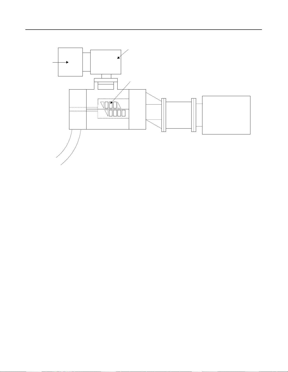
4-2
Air Filter
Application Profiles for the SMC Dialog Plus Controller
Figure 4.1 Compressor with Soft Start
Inlet Valve
Tur n Valve
Ports
208-480 Volts
50-250 HP
50/60 Hz
Motor
Problem: A compressor OEM shipped its equipment into overseas
markets. There were many different voltage and
frequency req u irements to me e t because o f the
compressor’s final destination. Due to power company
requirements and mechanical st r ess on the compressor,
reduced voltag e starter was requ ired. This made ordering
and stocking spare parts difficult. Energy savings was
desired because this is typically one of the larger motors
in the plant and it frequently runs lightly loaded. Also,
because of the size of the motor, the incoming line
voltage unbalance was causing excessive heating in th
motor.
Solution: The SMC Dialog Plus controller was installed and set for
an 18-second Soft Start, which reduced the voltage to the
motor during starting and met the power company
requirements. By reducing the voltage, the starting
torque was also reduced, minimizing the shock to the
compressor. Panel space was saved because the SMC
Dialog Plus controller has a built-in overload feature.
The Phase Rebalance feature automatically adjusted the
voltage out put to balance th e thre e- ph as e c u rre nts drawn
by the motor. In addition, the Energy Saver feature
optimized the voltage to the motor while it was running
unloaded.
Page 85

Application Profiles for the SMC Dialog Plus Controller
Figure 4.2 Tumbler with Dual Ramp Start
Loading Door
4-3
480 Volts
25 HP
Tumbler Drum
Motor
Drive Chain
Problem: A tumbler used in a na il finishing process was breaking
the drive chain because of uncontrolled acceleration from
the across-the-line start. In addition, a reversing starte
was needed to position the drum to the top position for
loading the product . Because o f the l a ck of controlled
acceleration, numerous jogs were used to position the
drum. The stopping time was not a con cer n in this
application. When in maintenance mode, the tumbl e
started unloaded, reaching full speed very quickly. A
second starting ramp, for unloaded conditions, was
desired. Additionally, single phasing of the motor was a
frequent problem , causing prem a ture m o tor f ailure.
Solution: The SMC Dialog Plus controller was installed after the
reversing contactor to control the starting torque of th
motor . This decreased the sn apping of the drive chain on
start up, which in t ur n i ncreased the life of the ch a in and
reduced the downtime on the tumbler. In addition, the
SMC Dialog Plus controller made i t eas ie r t o j o g the
drum into position for loading and unloading. (The SMC
Dialog Plus controller slowed the acceleration rate to
prevent overshoot.) When in maintenance mode, the
Dual Ramp Start feature of the SMC Dialog Plus
controller was utilized to provide a soft start specifically
for no lo ad con ditions. Thi s improved the productivity of
the loading and unloading process. Further, the SMC
Dialog Plus controller quickly detected a phase failure
during either t he st ar ting or r u nn i ng mo d es. The
controller would shut off with a “line fault” condition and
prevent restarting t he m o tor until the line had been
corrected. This provided additional protection to the
motor and system.
Page 86

4-4
Application Profiles for the SMC Dialog Plus Controller
Figure 4.3 Tumbler with Soft Start and SMB Smart Motor Braking Option
480 Volts
150 H
Loading Door
Tumbler Drum
Motor
Drive Chain
Problem: A tumbler drum used in the de-burring pro cess was
breaking the drive c h ain becau se of the uncontrolled
acceleration from the across-the-line starte r. To increase
production on the drum, the coasting time on stop had to
be reduced. Previous solutions were a separate soft start
package plus a motor brake, which required additional
panel space and power wiring. A small enclosure siz
and simplified power wiring were needed to reduce the
cost of the controls. Because a PLC was controlling
several other processes i n t he facility, communi cation
capabilities were desired.
Solution: The SMC Dialog Plus controller with the SMB Smart
Motor Braking option was installed on the process. The
Soft Start provided a smooth acceleration of the drive
chain, which reduce d downtime. The controlled
acceleration made positioning for loading/unloading
easier. The SMB Smart Motor Braking option allowed
the system to be stopped quickly, improving productivi ty.
Further, the SMB Smart Motor Braking option did not
require additional panel space or wiring. The SMC
Dialog Plus controller’s built-in o verload elim inated the
need to mount an external overload relay in the
enclosure, saving further pan el space. The
communic a tion feature of the SM C Dialog P lus
controller allowed for remote starting and stopping of th
process f rom a PLC.
Page 87

Application Profiles for the SMC Dialog Plus Controller
Figure 4.4 Tumbler with Accu-Stop Option
Loading Door
4-5
480 Volts
150 H
Tumbler Drum
Motor
Drive Chain
Problem: A tumbler drum used in a hide processing plant required
a controlled acceleration to prevent the drive chain from
breaking. In addition, it was desirable to minimize the
loading and unloading time. The drum would coast for a
long period of ti me before stop pi ng for unloading.
Previously, a soft start with electronic brake had been
applied. This method still required excessive jogging for
loading and unloading, which resulted in extended
production times. It also required additio nal panel space
and wiring for the brake. Consequently, higher
installation costs were incurred.
Solution: The SMC Dialog Plus controller with the Accu-Stop
option was installed. This allowed the dr um t o b
positioned fo r loading using th e Pres et Slow Speed. For
unloading, the drum was rotated at Preset Slow Speed
and then accurately stopped. This in crea s ed the
productivity of the loading/unloading cycle. The SMC
Dialog Plus controller required no additional panel space
or power wiring, facilitating a smooth retrofit and
reducing the installation costs.
Page 88

4-6
Application Profiles for the SMC Dialog Plus Controller
Figure 4.5 Pump with Soft Start
Ground Level
Check Valve
Motor
480 Volts
30 HP
Pump
Problem: A municipal water company was experiencing problems
with pump i mpellers b ei n g damag ed. The damage
occurred during an across-the-line start and was caused
by the heavy shock to the impeller. The pumping station
motor was over 100 feet below ground, making repair
costly. For maintenance scheduling purposes, an elapsed
time meter measuring motor running time had to b
installed in the enclosure. Additional concerns were
energy consumption and frequent line failures, which
resulted in single phasing the motor.
Solution: The SMC Dialog Plus controller was installed, providing
a controlled acceleration of the motor. By decreasing the
torque during start-up, the shock to the impeller was
reduced. The SMC Dialog Plus controller’s built-in
Energy Saver feature was automatically activated
whenev er the pump was lightly l oade d for long periods of
time. Panel space was saved by employing the built-in
elapsed time meter. The SMC Dialog Plus controller’s
line diagnostics detected the pre-start and running single
phase condition and shut off the motor, thereby
protecting against motor damage.
Page 89

Application Profiles for the SMC Dialog Plus Controller
Figure 4.6 Pump with Pump Control Option
480 Volts
150 HP
Motor
4-7
Check Valve
Intake
Outlet
Pump Housing
Problem: A municipal pump wa s uti lizing a soft start co n tr oller
with soft stop to control the pump motor. The soft stop
was controlling the motor in an open loop fashion by
reducing the voltage to the motor. Because there was not
enough torque provided t o the motor to dr ive the load, the
motor’s stall point was quickly reached. During the stop
mode, severe surges were causing pipe vibration and
breakage.
Solution: The SMC Dialog Plus controller with the Pump Control
option was installed. The Pump Control option removed
the surges by controlling the speed of the motor during
starting and stopping. The microprocessor inside the
SMC Dialog Plus controller analyzed the motor variables
and generated control commands to reduce the surges in
the system.
Page 90

4-8
Application Profiles for the SMC Dialog Plus Controller
Figure 4.7 Bandsaw with Soft Start
480 Volts
300 HP
Saw Blade
Log
Carriage
Motor
High Inertia Wheels
Problem: Because of the remote location of the facility and powe
distribution limit a tio ns, a reduced voltag e starter was
needed on a ba ndsaw applicat i on. The saw was turned
off only during shift changes. When the saw b lade
became dull, the curre nt drawn by the motor increased.
Therefore, an ammeter was required. Metering th
application for jam con diti on s w as a necessity. In
addition, single phasing of the motor was a problem
because of distribution limitations.
Solution: The SMC Dialog Plus controller was installed to provid
a reduced voltage start. This minimized the starting
torque shock to the system. The Energy Saver feature
was activated whenever the bandsaw was running lightly
loaded. The current monitoring and jam detection
features of the SMC D ial og Plu s con troll e r w ere
implemented, saving valuable panel space and the cost o
purchasing dedicated monitoring devices. The
controller’s built-in programmable ove rl oad protection
was utilized. The SMC Dialog Plus controller’s
diagnostic capabilities would detect single phasing and
shut the motor off accordingly.
Page 91

Saw Blade
Motor
Application Profiles for the SMC Dialog Plus Controller
Figure 4.8 Bandsaw with Soft Start and SMB Smart Motor Braking Option
480 Volts
250 HP
Log
Carriage
High Inertia Wheels
4-9
Problem: A bandsaw application required a reduced voltage start
because o f power company res trictions. A brake package
was required to reduce the stopping time of the saw.
Previously, an autotransformer had been used to start the
saw. The saw was stopped by sawing down. Sawing
down is accomplished by running logs through the saw
after the motor has been de-energized, which results in
large amount of scrap lumber . Other stopping methods
using de d ic ated b raking devic es were investigated but
were unacceptable because of overly complex
installation. Additionally, other stopping methods
required panel space for the brake module, brak
contactors and time rs , and they offered no z er o s peed
detection.
Solution: The SMC Dialog Plus controller with the SMB Smart
Motor Braking option was installed. It provided the
reduced voltage start needed to meet the po wer company
restrictions. The SMB Smart Motor Braking option did
not require additi onal panel space or DC braking
contactors. The starting and stopping control was
furnished in a single modular design, providing ease of
installation.
Page 92

4-10
Application Profiles for the SMC Dialog Plus Controller
Figure 4.9 Bandsaw with Soft Start and Slow Speed with Braking Option
480 Volts
300 HP
Saw Blade
Log
Carriage
Motor
High Inertia Wheels
Problem: A bandsaw required 25 minutes to coast to a stop to
routinely c ha nge the saw blade. A braking package was
required to reduce the stopp in g time. Othe r me thods
using de d ic ated b raking devic es were investigated but
were unacceptable because of overly complex
installation. These methods required additional panel
space for the brake module, brake contactors, and timers.
Because of p ot e nt ia l alignment problems, it was
dangerous to bring the saw up to full speed afte
installing a new blade.
Solution: The SMC Dialog Plus controller with the Slow Speed
with Braking option was installed. It provided a Preset
Slow Speed, allowing the saw blade tracking to b
inspected before the motor was brought to full speed.
The brakin g option of the SMC Dialog P l us controlle
did not require additional panel space or DC braking
contactors. Starting and stopping control was furnished
in a single modular unit, p roviding ease of installation.
Page 93

Application Profiles for the SMC Dialog Plus Controller
Figure 4.10 Trolley with Dual Ramp Start
240 Volts
10 HP
Motor
4-11
Tow Chai n
Problem: A trolley carrying ceramic tiles entered a kiln for heating.
When heated, the trolley exited the kiln and entered th
production area. Any abrupt mov e ment caused the tiles
to fall over, resulting in damaged product. An across-theline starter, gearbox, and fluid coupling were used to
perform this work, with some lost production expected.
Solution: The SMC Dialog Plus controller was installed to utiliz
acceleration control, which resulted i n improved
productivity and a reduction i n damaged product. Th
maintenance ti me for the fluid coupling was also
minimized. Further, the Dual Ramp Start feature allowed
for two separate acceleration ramps to be programmed;
one ramp for a start w ith a heavy load, and on e for a start
with the lighter tiles loaded.
Page 94

4-12
Application Profiles for the SMC Dialog Plus Controller
Figure 4.11 Trolley with Soft Start and Preset Slow Speed Option
240 Volts
10 HP
Tow Chai n
Motor
Problem: A trolley application required a slow speed, as well as
soft start, to eliminate product tipping while accelerating
from rest. A variable frequency drive was considered.
However, variable speed was not required during the run
cycle. A cost-effective solution was desired.
Solution: The SMC Dialog Plus controller with the Preset Slow
Speed option was i ns ta lle d . The Pr eset Slow Speed of
15% of rated speed was selected. After running at 15
of full speed for a few seconds, a 25-second ramp start
was selected to acc elerate the m o to r to full s pe ed. The
SMC Dialog Plus controller with Preset Slow Speed
helped protect against product tipping during start-up. In
addition, the desired accel erati on cont rol was provi ded at
a reasonable cost.
Page 95

Application Profiles for the SMC Dialog Plus Controller
Figure 4.12 Exhaust Fan with Soft Start
Exhaust Intake
Belts
Motor
4-13
480 Volts
60 HP
Problem: The belts on an exhaust fan were frequently breaking,
causing maintenance problems. In addition to the high
cost of the belts, the fan belt guard was cumbersome to
remove. The high starting torque from the motor was
major contr ibu tor to t h e belt wear. Also, re mote st ar ting
and stoppin g of the fan f ro m a PLC w as desired. Panel
space was limit ed, re qu i ring a compact device.
Solution: The SMC Dialog Plus controller was installed as a
retrofit to the existing starter. The ramp time was set for
28 seconds, facilitating a smooth acceleration while
reducing the starting torque of the motor and minimizing
the mechani ca l shock to th e be lts. The SMC Dialog Plus
controller ha s commu ni c ation capabilities built-in,
allowing for remote control via a PLC. It also has builtin overload protection, which saved valuable panel space.
Page 96
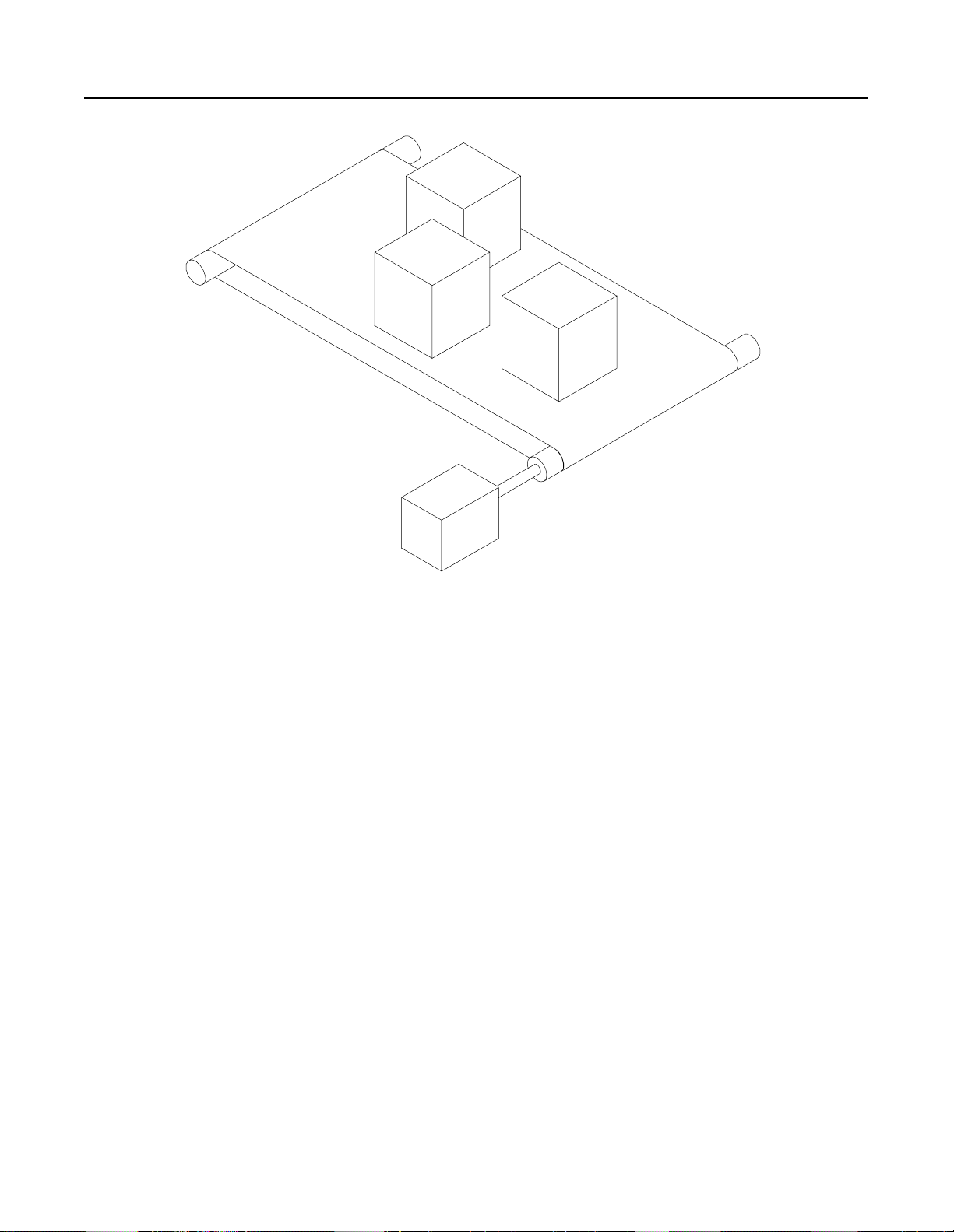
4-14
Application Profiles for the SMC Dialog Plus Controller
Figure 4.13 Palletizer with Dual Ramp Start
480 Volts
1-1/2 HP
Motor
Problem: A palletizer moved ce r eal boxes throu gh a pac kaging
process to a shrink wrap machine. Across-the-line
starting caused unwanted product spillage, as well as an
interruption of production due to the uncontrolled torque
from the motor on start-up. Since several types of
cereals, in different size boxes , wer e produced on the
same line, the ability to match the acceleration ramp to
the cereal was desired. The facility was standardized on
Allen-Bradley’s Motor Control Centers. Therefore, the
installation of the soft start in an MCC plug-in bucket
was required.
Solution: The SMC Dialog Plus controller was installed , furnishing
a controlled acceleration, reducing the shock to the load,
and eli minating product spillage. The Dual Ramp Start
feature al lowed the controller to be programmed with two
separate acceleration ramps, more closely matching the
motor acceleration with the cereal produced. The SMC
Dialog Plus controller was installed in a Motor Control
Center plug-in bucket, maki ng the packaging attractive t o
the customer and eliminating the need for a stand-alone
enclosure.
Page 97

Application Profiles for the SMC Dialog Plus Controller
Figure 4.14 Palletizer with Soft Start and Preset Slow Speed Option
240 Volts
7.5 HP
Bander
Paper
Stacks
Motor
4-15
Problem: Stacks of paper on a conveyor were moved to a bander
and then moved through the bander process onto a skid.
When the papers were loose, a cont ro lled low speed
acceleration into the bander was required. After the
papers were bound, a soft start was needed t o keep the
bundles from falling off the palletizer. The expense of a
variable frequency drive to control the motor speed was
not feasible.
Solution: The SMC Dialog Plus controller with the Preset Slow
Speed option was insta lled, eliminat ing the need for
frequent jogging of the conveyor to align the load with
the bander . The loose papers were moved into the bander
at 15% of full speed. A Soft Start was used to accelerat
the motor to full speed, and load the bound stacks on th
skid. The SMC D ia l og Plus controller was a cost
effective method of achieving the results required by the
application.
Page 98

4-16
Application Profiles for the SMC Dialog Plus Controller
Figure 4.15 Rock Crusher with Soft Start
Motor: 250
480 Volts
Starts: Unloaded
Gearbox
Motor
Discharge
Problem: Because of the remote location of a rock quarry, the
power company requi red a reduced voltag e start on all
motors over 150 HP. The starting current on these larg
motors strain ed the capacity of the p o we r sy st em, causing
severe voltage dips. When the rock crusher became
overloaded, th e c urrent drawn by th e motor incr eased.
Therefore, current monitoring capabilities within the soft
starter were required. Because the conveyor feeding the
rock crusher was controlled by a PLC, communications
between the soft star ter and a PLC w a s n ec es sary. The
rock crusher ran unloaded at times, and occasionally
stall or jam would occur.
Solution: The SMC Dialog Plus controller was installed, meeting
the power company requirements. The metering
capabilities of the SMC Dialog Plus controller allowed
the current draw n by t he motor to be monitored . With the
built-in communications capabilities, the motor current
could then be communicated to the PLC. When the
motor current reached a specified limit, the conveyor
feeding the rock cr us her could be slowed. By slowing
the conveyor, a jam condition in the rock crusher was
avoided. The Energy Saver feature of the controlle
reduced the voltage to the motor when the system was
running lightly loaded. The stall and jam detection
capabilities of the SMC Dialog Plus controller would
shut off the motor when a stall or jam condition oc curred.
Page 99

Input
Shredder Teeth
Application Profiles for the SMC Dialog Plus Controller
Figure 4.16 Shredder with Soft Start
Scrap
4-17
480 Volts
200 HP
Motor
Output
Gearbox
Problem: Because of power company restrictions, a metal shredder
required a reduced voltage start. Occasionally, a jam
would occur during the shredding process. Additionally,
the equipment ran unloaded for long periods. An
autotransformer-type starter had been used in the past.
Solution: The SMC Dialog Plus controller was installed,
facilitating a re duced vo lta ge start. The controller also
provided jam detection, which helped protect against
excessive motor heating when a ja m condition was
encounter ed. Th e Energy Saver feature o f t he SMC
Dialog Plus controller reduced the volt ag e to the motor
when the motor was running lightly loaded. The built-in
overload feature of the control ler saved valuable panel
space.
Page 100

4-18
Application Profiles for the SMC Dialog Plus Controller
Figure 4.17 Hammermill with Current Limit Start
480 Volts
250 HP
Hammer
Feed
Belts
Motor
Problem: A hammermill with a high inertia load required a reduced
voltage sta rt be cause of pow er comp any restrictions.
High torque on start-up was causing belt wear. Panel
space was very limited. Traditional reduced voltage
starters would not fit in the available space.
Solution: The SMC Dialog Plus controller was installed and set for
a 23-second, 425% current limit start, which met the
power company’s requirement for the reduced voltage
start. The belt life was extended since the starting torque
was re duced. A current limit start was selected to quickly
break away the high inertia load and still provide a
reduced volt age start . The Energ y Saver feature was used
when the mill was running lightly loaded. The compact
size of the SMC Dialog Plus controller, along with th
built-in overload feature, enabled the controller to fit into
the available panel space.
 Loading...