

Page 1

User Manual
Elevator Panel Solution
Bulletin 150-E
Page 2
Important User Information
IMPORTANT
Solid-state equipment has operational characteristics differing from those of electromechanical equipment. Safety
Guidelines for the Application, Installation and Maintenance of Solid State Controls (publication SGI-1.1
your local Rockwell Automation sales office or online at http://www.rockwellautomation.com/literature/
important differences between solid-state equipment and hard-wired electromechanical devices. Because of this difference,
and also because of the wide variety of uses for solid-state equipment, all persons responsible for applying this equipment
must satisfy themselves that each intended application of this equipment is acceptable.
In no event will Rockwell Automation, Inc. be responsible or liable for indirect or consequential damages resulting from
the use or application of this equipment.
The examples and diagrams in this manual are included solely for illustrative purposes. Because of the many variables and
requirements associated with any particular installation, Rockwell Automation, Inc. cannot assume responsibility or
liability for actual use based on the examples and diagrams.
No patent liability is assumed by Rockwell Automation, Inc. with respect to use of information, circuits, equipment, or
software described in this manual.
Reproduction of the contents of this manual, in whole or in part, without written permission of Rockwell Automation,
Inc., is prohibited.
Throughout this manual, when necessary, we use notes to make you aware of safety considerations.
WARNING: Identifies information about practices or circumstances that can cause an explosion in a hazardous
environment, which may lead to personal injury or death, property damage, or economic loss.
available from
) describes some
ATTENTION: Identifies information about practices or circumstances that can lead to personal injury or death,
property damage, or economic loss. Attentions help you identify a hazard, avoid a hazard, and recognize the
consequence
SHOCK HAZARD: Labels may be on or inside the equipment, for example, a drive or motor, to alert people that
dangerous voltage may be present.
BURN HAZARD: Labels may be on or inside the equipment, for example, a drive or motor, to alert people that
surfaces may reach dangerous temperatures.
Identifies information that is critical for successful application and understanding of the product.
Allen-Bradley, Rockwell Software, Rockwell Automation, and TechConnect are trademarks of Rockwell Automation, Inc.
Trademarks not belonging to Rockwell Automation are property of their respective companies.
Page 3

Introduction
Table of Contents
Chapter 1
. . . . . . . . . . . . . . . . . . . . . . . . . . . . . . . . . . . . . . . . . . . . . . . . . . . . . . . . . . . . . . . . . . . 5
Component Overview . . . . . . . . . . . . . . . . . . . . . . . . . . . . . . . . . . . . . . . . . . . . . . 5
Base Controller . . . . . . . . . . . . . . . . . . . . . . . . . . . . . . . . . . . . . . . . . . . . . . . . 6
Fault Contactor . . . . . . . . . . . . . . . . . . . . . . . . . . . . . . . . . . . . . . . . . . . . . . . . 6
Function Overview. . . . . . . . . . . . . . . . . . . . . . . . . . . . . . . . . . . . . . . . . . . . . . . . . 7
Motor Control . . . . . . . . . . . . . . . . . . . . . . . . . . . . . . . . . . . . . . . . . . . . . . . . . 7
Diagnostics . . . . . . . . . . . . . . . . . . . . . . . . . . . . . . . . . . . . . . . . . . . . . . . . . . . . 7
Starter Selection. . . . . . . . . . . . . . . . . . . . . . . . . . . . . . . . . . . . . . . . . . . . . . . . . . . . 8
For 6 or 12 Lead Wye-Delta Wound Motors . . . . . . . . . . . . . . . . . . . . . 8
For 3- or 9-Lead Closed Delta-Type Motors . . . . . . . . . . . . . . . . . . . . . . 8
Chapter 2
Installation & Wiring
Programming
Troubleshooting
Unpacking. . . . . . . . . . . . . . . . . . . . . . . . . . . . . . . . . . . . . . . . . . . . . . . . . . . . . . . . . 9
Mounting . . . . . . . . . . . . . . . . . . . . . . . . . . . . . . . . . . . . . . . . . . . . . . . . . . . . . . . . . 9
Dimensions. . . . . . . . . . . . . . . . . . . . . . . . . . . . . . . . . . . . . . . . . . . . . . . . . . . . . . . . 9
Installation Precautions. . . . . . . . . . . . . . . . . . . . . . . . . . . . . . . . . . . . . . . . . . . 11
Terminal Torque Specifications . . . . . . . . . . . . . . . . . . . . . . . . . . . . . . . . . . . 12
Delta Connection . . . . . . . . . . . . . . . . . . . . . . . . . . . . . . . . . . . . . . . . . . . . . . . . 13
Delta Connection (continued) . . . . . . . . . . . . . . . . . . . . . . . . . . . . . . . . . . . . 14
Line Connection . . . . . . . . . . . . . . . . . . . . . . . . . . . . . . . . . . . . . . . . . . . . . . . . . 15
Line Connection (continued) . . . . . . . . . . . . . . . . . . . . . . . . . . . . . . . . . . . . . 16
Delta-Connected Controller . . . . . . . . . . . . . . . . . . . . . . . . . . . . . . . . . . . . . . 17
Line-Connected Controller . . . . . . . . . . . . . . . . . . . . . . . . . . . . . . . . . . . . . . . 18
Chapter 3
DIP Switch Settings . . . . . . . . . . . . . . . . . . . . . . . . . . . . . . . . . . . . . . . . . . . . . . 19
Motor FLA Requirements . . . . . . . . . . . . . . . . . . . . . . . . . . . . . . . . . . . . . . . . 21
Motor Overload Trip Curves. . . . . . . . . . . . . . . . . . . . . . . . . . . . . . . . . . 21
Input & Output Timing . . . . . . . . . . . . . . . . . . . . . . . . . . . . . . . . . . . . . . 22
Chapter 4
Introduction. . . . . . . . . . . . . . . . . . . . . . . . . . . . . . . . . . . . . . . . . . . . . . . . . . . . . 23
Diagnostics Indication. . . . . . . . . . . . . . . . . . . . . . . . . . . . . . . . . . . . . . . . . . . . 23
Troubleshooting Steps. . . . . . . . . . . . . . . . . . . . . . . . . . . . . . . . . . . . . . . . . . . . 25
Repair Parts. . . . . . . . . . . . . . . . . . . . . . . . . . . . . . . . . . . . . . . . . . . . . . . . . . . . . . 26
Specifications
Chapter 5
Electrical . . . . . . . . . . . . . . . . . . . . . . . . . . . . . . . . . . . . . . . . . . . . . . . . . . . . . . . . 27
Mechanical . . . . . . . . . . . . . . . . . . . . . . . . . . . . . . . . . . . . . . . . . . . . . . . . . . 29
Environmental . . . . . . . . . . . . . . . . . . . . . . . . . . . . . . . . . . . . . . . . . . . . . . . 29
Dimensions & Shipping Weights . . . . . . . . . . . . . . . . . . . . . . . . . . . . . . . . . . 30
Rockwell Automation Publication 150-UM009D-EN-P - February 2011 3
Page 4

Table of Contents
4 Rockwell Automation Publication 150-UM009D-EN-P - February 2011
Page 5
Chapter
Base
Controller
Fault
Contactor
1
Introduction
This manual provides and overview of the installation, set-up, and typical
operation of the Allen-Bradley hydraulic elevator and escalator starter. This solidstate starter solution is designed to operate 3-phase standard squirrel cage
induction motors and can be connected to a 6 or 12 lead Wye-Delta or standard 3
or 9 lead motors. Through the use of LINE or INSIDE-THE-DELTA control,
the solid-state solution can provide ultimate control of the motor. The advantages
of a solid-state solution include the following:
• Provides smooth motor starting.
• Reduces current surges on weak electrical systems.
• Reduces starting torque of the motor, wich helps to reduce mechanical
stress on system components.
• Helps meet both local and regional electrical codes when reduced voltage
starting is a requirement.
• Eliminates voltage and current spikes associated with traditional WyeDelta starters.
• Maximizes the life of the motor with reduced electrical strain.
• Reduces general system maintenance requirements for improved uptime.
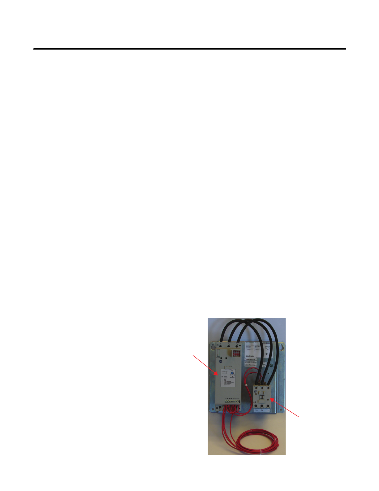
Component Overview
The starter is made up of two components, the base controller and a fault
contactor.
Figure 1 - Bulletin 150-E Components
Rockwell Automation Publication 150-UM009D-EN-P - February 2011 5
Page 6

Chapter 1 Introduction
Base Controller
The base controller is a standard product that uses a number of intelligent
features to provide advanced motor control and simple diagnostics. The base
controller consists of the elements necessary to control the motor. These elements
include:
• a main micro-processor
• current sensing
• built-in adjustable overload
• solid-state power modules, and
• electro-mechanical bypass contacts.
Through the use of simple DIP switch configuration, the product can be
configured for a variety of modes. The default configuration uses the built-in
current sensing to limit current to the motor during starting. Once up to speed,
the base controller transitions to the run mode by transitioning to internal bypass
contactors and changing the state of the auxillary contact. The internal bypass
contactor provides decreased heating during run and removes the SCRs from the
circuit.
Fault Contactor
The fault contactor is controlled through the fault contact of the controller.
When control power is applied to the controller, the normally open fault contact
closes and applies control power to the coil of the contactor. The fault contact
will open, removing power from the fault contactor, and thus disabling the motor
during any one of the following events:
• The power is removed from the controller.
• The motor has developed a problem including overloading due to one of
the following:
– Mechanical or electrical reasons
– Ground faults or
– Motor short circuits.
• The starter has detected an internal problem such as a shorted SCR or
overtemperature condition.
6 Rockwell Automation Publication 150-UM009D-EN-P - February 2011
Page 7

Introduction Chapter 1
Function Overview
The Bulletin 150-E elevator panel provides solution to both advanced motor
control and simple diagnostics. The following information provides a brief
overview of the basic product features.
Motor Control
Current Limit Through the use of internal current sensors, the SMC™ will regulate the current
Soft Start The voltage is ramped from an initial set point to full voltage over the programmed
Soft Stop The voltage is ramped down from full voltage and applied to the motor over a
level applied to the motor over the programmed period of time. This type of motor
control produces a slow start and insures that the current does not exceed the
programmed level. This is the standard configuration of the device and aligns well
with traditional applications.
period of time. This type of motor control produces a smooth start in less time
than the current limit setting. However, the current is not restricted.
programmed period of time. The result is a smooth stop.
Diagnostics
Overload Provides protection of the motor for over current conditions. This feature offers a
OverTemperature
Phase
Reversal
Phase Loss/
Open Load
Phase
Imbalance
Shorted SCR Each time the SMC initiates a start, it checks to see if the SCRs are operating
user-selectable setting called the trip class, which can be used to accommodate
different applications and motor types. When the motor draws more than the
nominal value of current for a period of time, the device will fault on a motor
overload fault.
A built-in self-monitoring method for detecting a SCR over-temperature condition. If
the internal temperature exceeds a design threshold, the device will fault on a SCR
Overtemp fault.
The user can select the phase relationship of the incoming power. If this phase
relationship changes, the device will fault indicating a problem.
When any one of the incoming 3 phases are lost, the controller will fault indicating
a phase loss condition has occurred.
When enabled, will detect if a phase imbalance condition exists and fault the unit.
A phase imbalance is defined as a 65% differential between the highest and
lowest phase for more than 3 seconds.
correctly. If the controller is unable to properly turn on and off any one of the SCRs,
the device will fault on a Shorted SCR fault.
Rockwell Automation Publication 150-UM009D-EN-P - February 2011 7
Page 8
Chapter 1 Introduction
Starter Selection
For 6 or 12 Lead Wye-Delta Wound Motors
The following table lists the catalog numbers that can be used with 6 or 12 lead
Wye-Delta motors. For proper operation, the connection should be verified
during installation. Sample connection diagrams for INSIDE-THE-DELTA
connected motors are included in the Installation and Wiring section found later
in this manual.
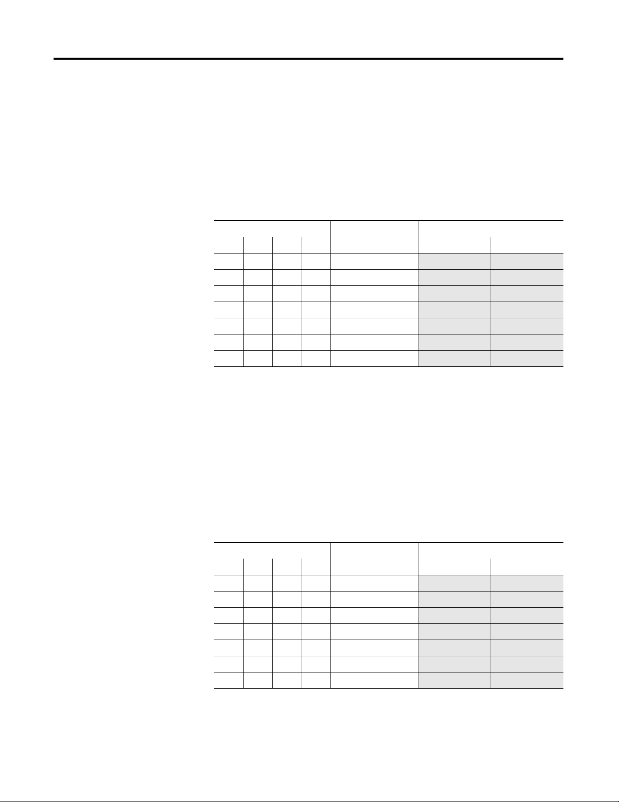
Table 1 - Cat. Nos. For Use with 6- or 12-Lead Wye-Delta Motors
Hp at Nominal Ratings
200V 240V 480V 575V 120V 230V
10 10 20 30 10.9…32.9
15 15 30 40 17…51 150-E51NCE-FC 150-E51NCA-FC
20 20 40 60 21.3…64 150-E64NCE-FC 150-E64NCA-FC
20 25 50 60 24.7…74
30 40 75 100 34.7…104 150-E104NCE-FC 150-E104NCA-FC
40 50 100 150 49…147 150-E147NCE-FC 150-E147NCA-FC
75 75 150 200 59…234
Motor FLA must fall within the specified range to operate correctly.
➊
Overload Range ➊
Control Voltage Cat. Nos.
150-E32NCE-FC 150-E32NCA-FC
150-E74NCE-FC 150-E74NCA-FC
150-E234NCE-FC 150-E234NCA-FC
For 3- or 9-Lead Closed Delta-Type Motors
The following table lists the catalog numbers that can be used with 3- or 9-lead
closed delta type motors. For proper operation, the connection should be verified
during installation. Sample connection diagrams for LINE connected motors are
included in the Installation and Wiring section found later in this manual.
Table 2 - Cat. Nos. For Use with 6 or 12 Lead Closed Delta-Type Motors
Hp at Nominal Ratings
200V 240V 480V 575V 120V 230V
5 5 10156.3…19 150-E32NCE-FC 150-E32NCA-FC
7.510202510…30
10 10 25 30 12.3…37
10 15 30 40 14.3…43 150-E74NCE-FC 150-E74NCA-FC
15 20 40 50 20…60
25 30 60 75 28.3…85
40 50 100 125 34…135
Motor FLA must fall within the specified range to operate correctly.
➊
Overload Range
➊
Control Voltage Cat. Nos.
150-E51NCE-FC 150-E51NCA-FC
150-E64NCE-FC 150-E64NCA-FC
150-E104NCE-FC 150-E104NCA-FC
150-E147NCE-FC 150-E147NCA-FC
150-E234NCE-FC 150-E234NCA-FC
8 Rockwell Automation Publication 150-UM009D-EN-P - February 2011
Page 9
Installation & Wiring
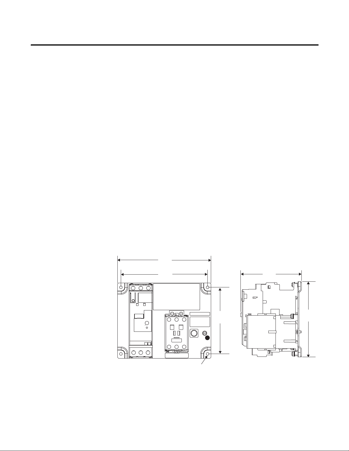
4.56
(115.7)
5.67
(144.0)
7.01
(178.0)
6.50
(165.1)
5.00
(127.0)
4X Ø 0.220 thru
(5.6)
CAT. XXXXXXXX SER. B
T6 T4 T5
1
Chapter
2
Unpacking
Mounting
Dimensions
Prior to installation, unpack the starter panel from its packaging and perform a
complete visual inspection of the panel. Inspect all components including the
controller, wiring, and fault contactor for damage related to shipping and
handling. Claims for damage must be made to the carrier as soon as possible after
receipt of the shipment.
The small footprint of the starter panel makes it ideal for mounting in the same
space previously occupied by legacy solid state starters and traditional Full
Voltage starters. The starter panel does not require mounting requirements
beyond the basic footprint of the panel.
The product may incorporate a small cooling fan. There are no additional cooling
requirements for the product. However, it is good practice to leave at least 6
inches (15.24 cm) of free space above and below the unit for ideal air flow.
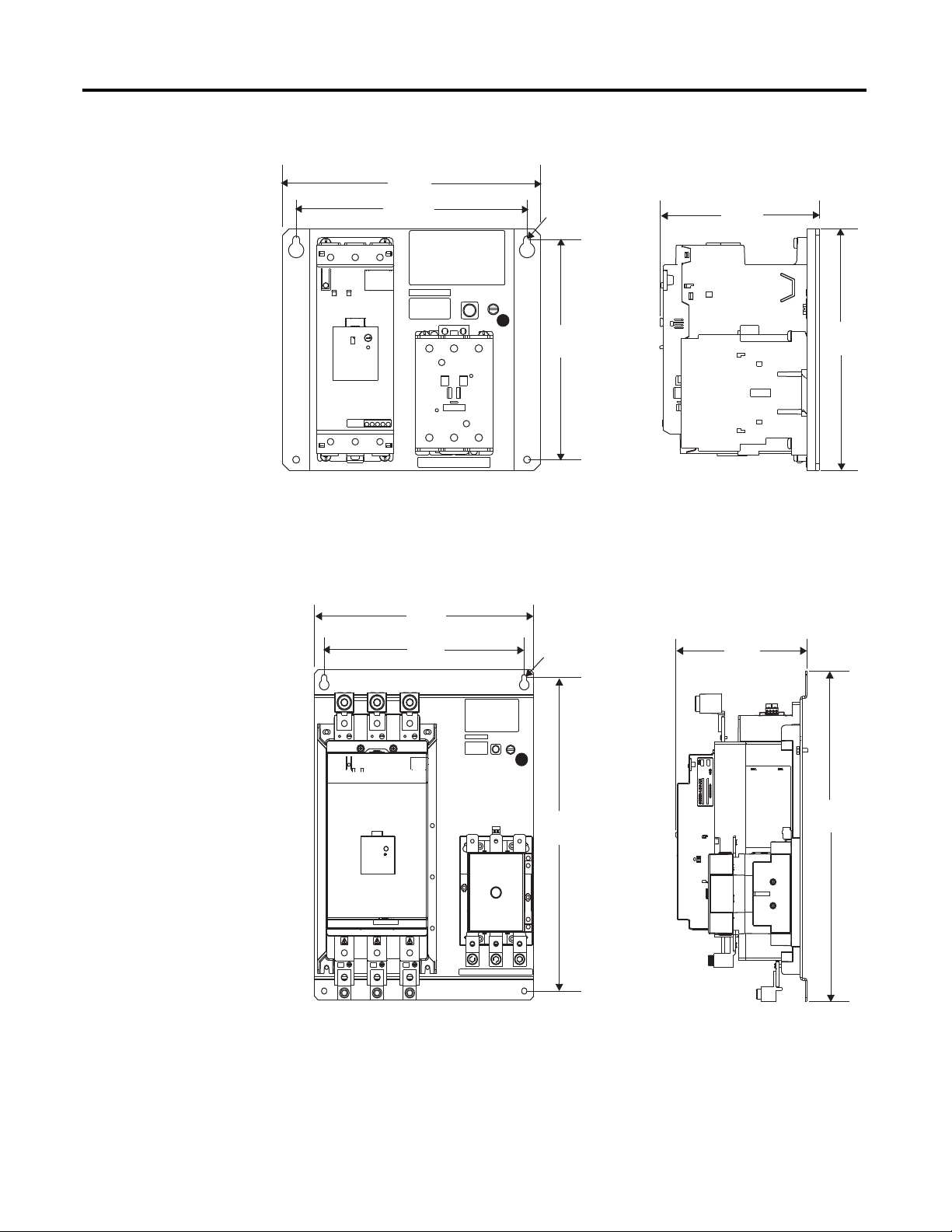
Figure 2 - Panel Dimensions for 32, 51, & 64 A Elevator Panels
This screw is intended to secure a prepared bonding conductor (e.g., a bonding conductor with a crimped-
➊
Rockwell Automation Publication 150-UM009D-EN-P - February 2011 9
on lug) or a suitable terminal for connection of an unprepared bonding conductor (e.g., a bonding
conductor with a stripped wire end). This screw is not intended for a direct field wiring connection of an
unprepared bonding conductor or equipment grounding conductor.
Page 10
Chapter 2 Installation & Wiring
8.86
(225.0)
5.82
(147.9)
9.45
(240.0)
8.46
(215.0)
8.07
(205.0)
4X Ø 0.260 Thru
(6.6)
CAT. XXXXXXXX SER. B
1
T6 T4 T5
20.28
(515.0)
8.52
(216.4)
1
4X Ø 0.343 thru
(8.7)
CAT. XXXXXXXX SER. B
14.25
(362.0)
13.00
(330.2)
19.27
(489.5)
T6 T4 T5
Figure 3 - Panel Dimensions for 74, 104, & 147 A Elevator Panels
➊
This screw is intended to secure a prepared bonding conductor (e.g., a bonding conductor with a crimped-
on lug) or a suitable terminal for connection of an unprepared bonding conductor (e.g., a bonding
conductor with a stripped wire end). This screw is not intended for a direct field wiring connection of an
unprepared bonding conductor or equipment grounding conductor.
Figure 4 - Panel Dimensions for 234 A Elevator Panels
➊
This screw is intended to secure a prepared bonding conductor (e.g., a bonding conductor with a crimped-
on lug) or a suitable terminal for connection of an unprepared bonding conductor (e.g., a bonding conductor
with a stripped wire end). This screw is not intended for a direct field wiring connection of an unprepared
bonding conductor or equipment grounding conductor.
10 Rockwell Automation Publication 150-UM009D-EN-P- February 2011
Page 11

Installation & Wiring Chapter 2
Installation Precautions
The following precautions are provided as guidance for proper installation of this
controller. As this product was designed to be used in a variety of applications,
not all precautions mentioned are relevant to your particular application. In all
cases, the local codes and standards governing this type of product must be
observed.
Motor Branch Protection and Disconnecting Means
• The controller featues motor overload protection. However, it does not
have means to protect itself from a short circuit condition. Suitable branch
circuit protection and coordination must be provided per the NEC, or the
equivalent local electrical code.
Electrical Noise Suppression
• Electrical noise can be generated from various sources connected to the
same power as the controller. Sources of noise include: inductive loads (i.e.
relays and solenoids), large motors and machinery, Variable Frequency
Drives, and other high frequency devices (i.e. welders).
• Electrical noise can enter the product through power and control wiring
and cause damage to solid-state components.
• Mitigation of electrical noise can be accomplished through the following
methods:
– Proper wiring practices including grounding, use of shielded cable
where appropriate, and separation of power, control, and signaling
wires.
– Use of surge suppression devices on inductive loads.
– Use of isolation transformers for high frequency generators.
Power Factor Correction Capacitors (PFCC).
• PFCCs must always be used on the line side of the controller. Use of
PFCCs on the output side of the controller will damage the starter.
Rockwell Automation Publication150-UM009D-EN-P - February 2011 11
Page 12

Chapter 2 Installation & Wiring
Terminal Torque Specifications
Table 3 - Controller Information
Controller
Size
32/51/64 Wire size 14…4 AWG
74/104/147 Wire size 14…3/0 AWG
234 Wire size 6…250 AWG
Units Line Load Control
(2.5…25 mm
Torque 20…25 lb-in.
(2.3…2.8 Nm)
(2.5…95 mm2)
Torque 100…110 lb-in.
(11.3…12.4 Nm)
(16…120 mm2)
Torque 275 lb-in.
(31 Nm)
Table 4 - Fault Contactor Information
Controller
Size
32/51/64 Wire size 14…6 AWG
74/104/147 Wire size 14…2 AWG
234 Wire size 6…300 AWG
Units Line Load Control
(2.5…16 mm
Torque 13…31 lb-in.
(2.3…3.5 Nm)
(2.5…35 mm2)
Torque 31…52 lb-in.
(3.5…6 Nm)
(16…150 mm
Torque 250 lb-in.
(28 Nm)
Power Terminals
2
)
2
)
2
)
14…6 AWG
(2.5…16 mm2)
20…22.5 lb-in.
(2.3…2.6 Nm)
14…1 AWG
(2.5…50 mm2)
100…110 lb-in.
(11.3…12.4 Nm)
6…250 AWG
(16…120 mm2)
275 lb-in.
(31 Nm)
Power Terminals
14…6 AWG
(2.5…16 mm2)
13…31 lb-in.
(2.3…3.5 Nm)
14…2 AWG
(2.5…35 mm2)
31…52 lb-in.
(3.5…6 Nm)
6…300 AWG
(16…150 mm2)
250 lb-in.
(28 Nm)
24…14 AWG
(0.2…2.5 mm2)
4.4…8 lb-in.
(0.5…0.9 Nm)
24…14 AWG
(0.2…2.5 mm2)
4.4…8 lb-in.
(0.5…0.9 Nm)
24…14 AWG
(0.2…2.5 mm2)
4.4…8 lb-in.
(0.5…0.9 Nm)
16…12 AWG
(1…4 mm2)
8.9…13 lb-in.
(1…1.5 Nm)
16…12 AWG
(1…4 mm2)
8.9…13 lb-in.
(1…1.5 Nm)
2x 16…12 AWG
(2x 1…4 mm2)
12…20 lb-in.
(1.4…2.3 Nm)
12 Rockwell Automation Publication 150-UM009D-EN-P- February 2011
Page 13

Installation & Wiring Chapter 2
1 — Contol Power (L1)
2 — Contol Common (L2)
4 — Start Enable
13 — Up-To-Speed Indication
Incoming Line Connections
T1 T2 T3 T6 T4 T5
L1 L2 L3
L1 L2 L3
[1] [4]
[2] [5]
[6] [3]
T3/6
L3/5
L2/3
T2/4
L1/1
T1/2
Incoming Lines
L1
L2 L3
[6] MOTOR [3]
SMC
FC
SMC
[1] MOTOR [4]
FC
[2] MOTOR [5] FC
SMC
(T6) (T3)
(1)
(L1)
(2)
(T1)
(T2) (T5)
(6)
(T3)
(5)
(L3)
(T1) (T4)
(4)
(T2)
(3)
(L2)
6 LEAD MOTOR CONNECTIONS
STARTER
TERMINALS
MOTOR
TERMINALS
T1 T2 T3 T6 T4 T5 JUMPER
1 2 3 6 4 5 N/A
MOTOR
T1 T2 T3
T6 T4 T5
3 6
2 4
1 5
234A ONLY
JUMPER
110/120V
220/240V
FAN
FAN
1 2 3 4
1 2 3 4
SMC CONTROL WIRES
FC
A1 A2 IN1 IN2 97 98 13 14
1 2
13
4
(A2) (A1)
1 2 1 2
SMC
1/L1 3/L2 5/L3
2/T1 4/T2 6/T3
A1 A2 IN1 IN2 97 98 13 14
FC
1/L1 3/L2 5/L3
T6 T4 T5
Delta Connection
Figure 5 - Diagram, Power, & Motor Wiring
Rockwell Automation Publication150-UM009D-EN-P - February 2011 13
Page 14

Chapter 2 Installation & Wiring
12 LEAD 230V LOW VOLTAGE MOTOR CONNECTIONS
STARTER
TERMINALS
MOTOR
TERMINALS
T1 T2 T3 T6 T4 T5 JUMPER
1&7 2&8 3&9 6&12 4&10 5&11 N/A
12 LEAD 460V HIGH VOLTAGE MOTOR CONNECTIONS
STARTER
TERMINALS
MOTOR
TERMINALS
T1 T2 T3 T6 T4 T5 JUMPER
1 2 3 12 10 11 4&7
5&8
6&9
[1] [4]
[2] [5]
[6] [3]
[12] [9]
[7] [10]
[8] [11]
[12] [9] [6] [3]
[2] [5] [8] [11]
[1] [4] [7] [10]
MOTOR
T1 T2 T3
T6 T4 T5
7 11
1 5
8 10
2 4
3 6
9 12
L2/3
T2/4
Incoming Lines
L1
L2 L3
SMC
MOTOR
FC
MOTOR
SMC
FC
FC
SMC
MOTOR
(1)
(L1)
(2)
(T1)
(T6) (T3)
(6)
(T3)
(5)
(L3)
(T2) (T5)
[12] [9] [6] [3]
(4)
(T2)
(3)
(L2)
(T1) (T4)
[1] [4] [7] [10]
[2] [5] [8] [11]
Incoming Lines
L1
L2 L3
SMC
[1] MOTOR [4]
FC
[6] MOTOR [3]
SMC
FC
(1)
(L1)
(2)
(T1)
(T6) (T3)
[12] [9]
[2] MOTOR [5] FC
SMC
(T2) (T5)
(6)
(T3)
(5)
(L3)
(T1) (T4)
(4)
(T2)
(3)
(L2)
[7] [10]
[8] [11]
L1/1
T1/2
T3/6 L3/5
L2/3
T2/4
T1 T2 T3
T6 T4 T5
MOTOR
3
2
1
12
10
11
4
7
8 5
9
6
T3/6
L3/5
L1/1
T1/2
Delta Connection (continued)
14 Rockwell Automation Publication 150-UM009D-EN-P- February 2011
Page 15

Installation & Wiring Chapter 2
Line Connection
1 2
FC
(A2) (A1)
4
A1 A2 IN1 IN2 97 98 13 14
1 — Contol Power (L1)
2 — Contol Common (L2)
4 — Start Enable
13 — Up-To-Speed Indication
FAN
1 2 3 4
1 2 1 2
110/120V
234A ONLY
JUMPER
Figure 6 - Diagram, Power, & Motor Wiring
13
SMC CONTROL WIRES
FAN
1 2 3 4
220/240V
L1
T1
L1
FC
T6
T1/2 L1/1
(1)
(L1)
(2)
(2)
(T1)
(T1)
[1]
L2
T2
L2
FC
T4
[2]
[2]
T2/4 L2/3
(3)
(L2)
(4)
(T2)
[3]
L3
T3
L3
FC
T5
T3/6 L3/5
(5)
(L3)
(6)
(T3)
Incoming Line Connections
L1 L2 L3
1/L1 3/L2 5/L3
SMC
A1 A2 IN1 IN2 97 98 13 14
2/T1 4/T2 6/T3
T1 T2 T3
L1 L2 L3
1/L1 3/L2 5/L3
FC
T6 T4 T5
T6 T4 T5
[1]
[3]
T6 T4 T5
2
1
3
MOTOR
3 LEAD MOTOR CONNECTIONS
STARTER
TERMINALS
MOTOR
TERMINALS
T6 T4 T5 JUMPER
1 2 3 N/A
Rockwell Automation Publication150-UM009D-EN-P - February 2011 15
Page 16

Chapter 2 Installation & Wiring
Line Connection (continued)
L1
T1/2 L1/1
T1
L1
FC
T6
[7]
(1)
(2)
[1]
(L1)
(T1)
[6]
L2
T2/4 L2/3
T2
L2
FC
T4
[2]
[4]
[8]
(3)
(4)
(L2)
(T2)
[9]
T3
L3
FC
T5
[5]
[3]
L3
T3/6 L3/5
(5)
(6)
(L3)
(T3)
L1
T1
L1
FC
T6
T1/2 L1/1
(1)
(L1)
(2)
(T1)
[4] [7]
[1]
L2
T2
L2
FC
T4
[2]
[9] [6]
T2/4 L2/3
(3)
(L2)
(4)
(T2)
[5] [8]
[3]
L3
T3
L3
FC
T5
T3/6 L3/5
(5)
(L3)
(6)
(T3)
[2]
[8]
[4]
[7]
[1]
[6]
T6 T4 T5
2
4 8
7 5
1 3
MOTOR
6 9
9 LEAD 230V LOW VOLTAGE MOTOR CONNECTIONS
STARTER
TERMINALS
MOTOR
TERMINALS
T6 T4 T5 JUMPER
1, 6, 7 2, 4, 8 3, 5, 9 N/A
[9]
[5]
[3]
[2]
[5] [8]
[4] [7]
[1]
T6 T4 T5
1
[3][9] [6]
2
3
MOTOR
9
6
9 LEAD 460V HIGH VOLTAGE MOTOR CONNECTIONS
STARTER
TERMINALS
MOTOR
TERMINALS
T6 T4 T5 JUMPER
1 2 3 4&7
5&8
6&9
8 5
4
7
16 Rockwell Automation Publication 150-UM009D-EN-P- February 2011
Page 17

Installation & Wiring Chapter 2
SCPD
MOTOR
1
SMC
(power connections)
FC
FC
FC
L3 T5
L2 T4
L1 T6
E-STOP
FC
START
UTS
INDICATION
GROUND
ENABLE
A1 A2
SMC CONTROL TERMINALS
A1 A2 IN1 IN2 97 98 13 14
OVERLOAD/
FAULT
AUX#1
(UTS)
H3 H2
H1 H4
X1 X2
TRANS.
L1/1
L2/3
L3/5
T1/2
T2/4
T3/6
1
1
1
Delta-Connected Controller
Figure 7 - Typical Control Wiring
➊ Customer supplied
Rockwell Automation Publication150-UM009D-EN-P - February 2011 17
Page 18

Chapter 2 Installation & Wiring
SCPD
MOTOR
1
SMC
(power connections)
FC
FC
FC
L3 T5
L2 T4
L1 T6
E-STOP
FC
START
UTS
INDICATION
GROUND
ENABLE
A1 A2
SMC CONTROL TERMINALS
A1 A2 IN1 IN2 97 98 13 14
OVERLOAD/
FAULT
H3 H2
H1 H4
X1 X2
TRANS.
L1/1
L2/3
L3/5
T1/2
T2/4
T3/6
1
1
1
AUX#1
(UTS)
Line-Connected Controller
Figure 8 - Typical Control Wiring
18 Rockwell Automation Publication 150-UM009D-EN-P- February 2011
➊
Customer supplied.
Page 19

Programming
Chapter
3
DIP Switch Settings
The 150-E elevator controller is programmed through DIP switches located on
the front of the controller. All functionality is defined by these settings. The
following tables define the settings available within the SMC™ controller. Default
settings are indicated by the shaded areas.
Table 5 - Start Time
Settings
(seconds)
2 OFF OFF
5ONOFF
10 OFF ON
15 ON ON
Table 6 - Start Mode
Mode Setting Switch #3
Current Limit OFF
Soft Start ON
Table 7 - Current Limit/Initial Torque Level
Switch #1 Switch #2
In Current Limit mode, a set level of current is applied to the
motor over the start time. In Soft Start mode, the device will
ramp the torque from the initial level to 100% over the start
time.
This defines the time the controller will ramp or
limit current to the motor. The controller can
determine when the motor is up-to-speed (UTS),
therefore it may transition to bypass before this
time expires. If the motor does not reach speed
before the time expires, the controller will
continue under SCR control and not close the
bypass contactor.
% FLA/ % Torque Switch #4 Switch #5
150%/15% OFF OFF
250%/25% ON OFF
350%/35% OFF ON
450%/65% ON ON
Table 8 - Soft Stop Time
Settings (seconds) Switch #6 Switch #7
OFF OFF OFF
1x start time ON OFF
2x start time OFF ON
3x start time ON ON
Rockwell Automation Publication 150-UM009D-EN-P- February 2011 19
The level indicated by this programming applies an
initial level of current or torque to the motor for the
start time. For example, if switch #3 is set to OFF,
the device will perform a current limit start at the
level indicated by these switches.
Soft Stop reduces the voltage applied to the
motor over the programmed period of time. The
soft stop is complete when the soft stop timer
has expired or the current measured drops below
50% of the FLA setting.
Page 20

Chapter 3 Programming
Table 9 - Phase Rotation
Setting Switch #9
The allowable phase rotation of the motor is defined by this switch.ABC rotation OFF
CBA rotation ON
Table 10 - Phase Imbalance
Setting Switch #10
Enabled OFF
Disabled ON
The controller has the ability to monitor for imbalance between phase
currents. This protection feature can be user-disabled.
Table 11 - Overload Trip Class
Setting Switch #11 Switch #12
OFF OFF OFF
10 ON OFF
15 OFF ON
20 ON ON
The controller incorporates, as standard, electronic
overload protection. This motor overload protection is
accomplished electronically with the use of internal current
transformers on each of the three phases. The controller’s
overload protection is programmable, providing the user
with flexibility.
Table 12 - Overload Reset
Setting Switch #13
Manual OFF
Auto ON
In manual reset mode, the fault can only be reset by pushing the ‘Push to
Reset’ button on the front of the controller. In auto reset mode, the unit will
automatically reset when the unit determines the motor has cooled to 75%
of its thermal capacity.
Table 13 - Aux #1 Setting
Setting Switch #14 The operation defines the operation of the Auxiliary contacts. Normal
Normal OFF
Up-to-Speed ON
mode means that the contact will change state immediately when a
start/run command is given. Up-to-Speed mode means that the contact
will change state only when the controller is in bypass. Aux#2, when
added, will operate opposite of this programming.
Table 14 - Motor Connection Type
Setting Switch #15
Delta OFF
Line ON
In DELTA connection mode, the device is designed to control a 6 or 12 lead
motor. In LINE connection mode, the device is designed to control a 3 or 9
lead motor.
Table 15 - Stop Delay
Setting(seconds) Switch #16
0.0 OFF
0.75 ON
20 Rockwell Automation Publication 150-UM009D-EN-P- February 2011
When the delay is programmed, the motor will continue to run
for the programmed period of time after the run command is
removed from the controller.
Page 21

Programming Chapter 3
∆ 32
19
Delta FLA
Line FLA
∆ 11
7
∆ 22
13
Service Factor _ _
FLA _ _
Service Factor < 1.15
Service Factor ≥ 1.15
= 0.9 X FLA
= 1.0 X FLA
= 1.0 X FLA
OR
Maximum Continuous Rated
(MCR) Motors
Motor FLA Requirements
The front of the SMC controller contains a dial which is used for setting the
actual FLA of the motor. The label is designed to accommodate motors
connected in the LINE or DELTA mode. To determine the proper setting, look
at the motor’s nameplate and set the dial accordingly. The dial setting can be
modified depending on the service factor of the motor.
Figure 9 - FLA Setting of Motor
Motor Overload Trip Curves
The trip class should be set according to the motor’s maximum permissible locked
rotor time or the general thermal capabilities. Consult the motor manufacturer
for recommendations on setting the trip class.
Figure 10 - Trip Class
Class 15
1000
800
600
400
200
80
60
40
20
8
6
4
2
0.8
0.6
0.4
0.2
4
2
1
6
100
10
1
0.8
0.6
0.4
0.2
0.1
8
10
1000
100
10
t (sec)
0.1
Class 10
800
600
400
200
80
60
40
20
8
6
4
2
1
0.8
0.6
0.4
0.2
4
2
1
1000
800
600
400
200
100
10
1
6
0.1
8
10
Multiple of FLA
Rockwell Automation Publication 150-UM009D-EN-P- February 2011 21
COLD START
HOT START
Class 20
80
60
40
20
8
6
4
2
4
2
1
6
8
10
Page 22

Chapter 3 Programming
Basic Timing Diagram, No Soft Stop
Possible Aux Contact Configuration
On
Off
Control Power
Start Enable
Fault Contact
(Fault Contactor)
Closed
Open
Up-to-Speed
Normal
Fault Occurs
Fault Reset
On
Off
Closed
Open
Closed
Open
Input & Output Timing
Figure 11 - Input & Output Timing
22 Rockwell Automation Publication 150-UM009D-EN-P- February 2011
Page 23

Troubleshooting
Chapter
4
Introduction
The following topics are designed to assist in the troubleshooting and
maintenance of the SMC™ controller. The items mentioned in this section are not
intended to be all-inclusive and it is expected that these items should be used as
reference only.
For safety of maintenance personnel as well as others who might be exposed to
electrical hazards associated with maintenance activities, follow the local safety
related work practices (i.e., the NFPA 70E, Part II in the United States).
Maintenance personnel must be trained in the safety practices, procedures, and
requirements that pertain to their respective job assignments.
SHOCK HAZARD:
Hazardous voltage is present in the motor circuit even when the 150-E
controller is off. To avoid shock hazard, disconnect the main power
before working on the controller, motor, and control devices (such as
Start-Stop push buttons). Procedures that require parts of the
equipment to be energized during troubleshooting, testing, etc., must
be performed by properly qualified personnel, using appropriate local
safety work practices and precautionary measures.
ATTENTION: Disconnect the controller from the motor before
measuring insulation resistance (IR) of the motor windings.
Voltages used for insulation resistance testing can cause SCR
failure. Do not make any measurements on the controller with an IR
tester (megger).
Diagnostics Indication
The LED on the front of the product provides limited status information
regarding the condition of the controller. The conditions are as follows:
• LED Off — No control power or start command given.
• LED On — The device is active with starting, running, or stopping.
• LED Flashes — A fault has been experienced. Refer to table below for
additional explanation.
Rockwell Automation Publication150-UM0009D-EN-P - February 2011 23
Page 24

Chapter 4 Troubleshooting
Table 16 - LED Fault Indication & Diagnostics
Flashes Fault Type Possible Fault Explanations Possible Solutions
1Overload • Motor overload condition present.
2 Over-Temperature • Controller ventilation blocked.
3 Phase Reversal • Incoming supply voltage is not the expected sequence. • Check power wiring.
4 Phase Loss/
Open Load
5 Phase Imbalance • Unbalanced Phase Currents (> 65% differential).
6 Shorted SCR • Shorted SCR.
7Test • Intended operation. • Reset fault.
12 Check Sum • Internal software corruption. • Replace device.
• FLA dial adjustment is not matched to motor type.
• Controller duty cycle exceeded.
• Cooling fan not working.
• Ambient temperature exceeded.
• Failed control module.
• Over-current condition with Overload disabled.
• Missing Supply Phase.
• Missing or unable to detect motor connection.
• Incoming line voltage problem.
• Welded or latched bypass contactor.
• Check for motor overload condition.
• Verify actual motor current does not exceed FLA.
• Verify/reset the FLA dial adjustment.
• Program/modify the Overload setting for load or duty
cycle required.
• Check for proper ventilation.
• Verify duty cycle.
• Connect or replace cooling fan.
• Wait for controller to cool or provide external coolin.
• Replace control module.
• Adjust dip switch #9 for desired sequence.
• Check for open line (i.e. open fuse).
• Check for incorrect wiring to load.
• Verify proper operation of the fault contactor.
• Verify connection type to motor (LINE or DELTA).
• Ensure product is sized correctly for motor.
• Check motor current in each phase to verify imbalance.
Motor current imbalance can indicate potential motor
problem.
• Verify connection type (LINE or DELTA) and verify setting.
• Perform continuity check across power poles (L1 – T1, L2
– T2, L3 – T3). Measurements should exceed 10 k ohms.
For best results, remove line and load motor connections.
• Cycle power to device and attempt to restart. If fault
persists, replace device.
24 Rockwell Automation Publication 150-UM0009D-EN-P - February 2011
Page 25

Troubleshooting Chapter 4
Troubleshooting Steps
Control Device Status Solution
Prestart - no start command given but device is faulted. LED Flashing • Reset fault.
Motor fails to start after start command given. LED Off • Check control power.
Motor attempts to start after start command is given,
but fails to reach an up-to-speed condition.
Motor stops abruptly and fails to restart. LED Off • Check for a blown fuse or tripped circuit breaker.
Fault contactor fails to close when power is applied. All Conditions • Verify wiring to the coil. The contactor should close when power is
Table 17 - Troubleshooting Steps
• Allow device to cool (overload or SCR over temp). Reset fault.
• Cycle power to device.
• Check control circuit connections.
LED ON • Verify proper operation of fault contactor or isolation devices.
• Check connections to the motor.
• Verify line power and frequency are within specifications.
LED Flashing • Reference the LED Fault Indication & Diagnostics Table for information
related to specific fault codes.
LED ON • Verify proper operation of the fault contactor or isolation devices.
• Verify line power and frequency are within specifications.
• Try increasing the initial torque or current limit setting.
LED Flashing • Reference the LED Fault Indication & Diagnostics Table for information
related to specific fault codes.
• Ensure the control power and start command are present.
• Verify proper operation of the fault contactor or isolation devices.
LED ON • Verify proper operation of the fault contactor or isolation devices.
LED Flashing • Reference the LED Fault Indication & Diagnostics Table for information
related to specific fault codes.
applied to the controller.
• Verify voltage across the coil (A1 to A2).
• Check the resistance of the coil. Replace, if measured open.
• Verify internal contact of the controller (terminals 97/98) are properly
changing state. Replace the controller if the contact does not operate
correctly.
Rockwell Automation Publication150-UM0009D-EN-P - February 2011 25
Page 26

Chapter 4 Troubleshooting
Repair Parts
Table 18 - Repair Parts
Panel Controller Contactor Fans Contactor Coil
150-E32NCE-FC 150-E32NCD 100-C37D00
(optional)
150-CF64
150-E64NCE-FC 150-E64NCD 100-C37D00
150-E74NCE-FC 150-E74NCD 100-C43D00
150-E104NCE-FC 150-E104NCD 100-C60D00 TE473
150-E147NCE-FC 150-E147NCD 100-C85D00 TE473
150-E234NCE-FC Complete Device 150-E234NCD
100-D180ED00 41391-801-03 TGE865Control Module 150-ES1BX
Power Pole 150-FPP135C
150-E32NCA-FC 150-E32NCD 100-C37KA00
150-E64NCA-FC 150-E64NCD 100-C37KA00
150-E74NCA-FC 150-E74NCD 100-C43KA00
150-E104NCA-FC 150-E104NCD 100-C60KA00 TE858
150-E147NCA-FC 150-E147NCD 100-C85KA00 TE858
150-E234NCA-FC Complete Device 150-E234NCD
100-D180EA00 41391-801-03 TGE866Control Module 150-ES1BX
Power Pole 150-FPP135C
150-CF147
(optional)
150-CF64
150-CF147
TC473150-E51NCE-FC 150-E51NCD 100-C37D00
TD473
TC858150-E51NCA-FC 150-E51NCD 100-C37KA00
TD858
26 Rockwell Automation Publication 150-UM0009D-EN-P - February 2011
Page 27

Specifications
Chapter
5
Electrical
Table 19 - Power Circuit
UL/cUL/CSA IEC
Rated Operational Voltage 200…600V AC 200…500V~
Rated Insulation Voltage 600V AC 500V~
Di-electric Withstand 2200V AC 2500V~
Repetitive Peak 200…600V AC: 1600 500V~: 1600
Rated Impulse Voltage 6 kV
Overvoltage Category III
Number of Poles Equipment designed for 3-phase only
Operating Frequency 50/60 Hz
Controller Utilization Category 32/52/64 AC-53b: 3.5-15:3585
74/104/147 AC-53b: 4.5-30:1770
234 AC-53b: 3.5-30:1770
Overlad Current Range (Amps) Line Delta
32 6.3...19 10.9...32.9
51 10...30 17...51
64 12.3...37 21.3...64
74 14.3...43 24.7...74
104 20...60 34.7...104
147 28.3...85 49...147
234 34...135 59...234
Rockwell Automation Publication 150-UM009D-EN-P - February 2011 27
Page 28

Chapter 5 Specifications
Table 20 - Control Circuit
UL/cUL/CSA IEC
Rated Operational Voltage 100...120V AC, 200...240V AC 120~, 240~
Rated Insulation Voltage — 300V~
Di-electric Withstand — 3000V
Rated Impulse Voltage 3 kV
Operating Frequency 50/60 Hz
Control Power Requirements 32/52/64 215 mA @ 120 V AC ,
180 mA @ 240 V AC
74/104/147 200 mA @ 120 V AC ,
100 mA @ 240 V AC
234 200 mA @ 120 V AC ,
120 mA @ 240 V AC
Fan Power Requrements 32/52/64 —
74/104/147 —
234 20VA
Table 21 - Short Circuit Capabilities
Short Circuit Performance Type 1
Device Current Rating Maximum Fuse Size & Type
70 A - RK5 5 kA
32
125 A - K5 5 kA
125 A - RK5 5 kA
51
200 A - K5 10 kA
125 A - RK5 5 kA
64
200 A - K5 10 kA
150 A - RK5 5 kA
74
250 A - J 10 kA
200 A - RK5 5 kA
104
400 A - J 10 kA
250 A - RK5 10 kA
147
400 A - J 10 kA
400 A - RK5 10 kA
234
450 A - K5 10 kA
Maximum Available Fault
Rating
28 Rockwell Automation Publication 150-UM009D-EN-P - February 2011
Page 29

Specifications Chapter 5
Table 22 - Auxillary Contacts (Fault & Aux #1)
UL/cUL/CSA IEC
Rated Operational Voltage 250V AC/30V DC 250V~ / 30V DC
Rated Insulation Voltage 250V 250V~
Di-electric Withstand —4 kV
Rated Impulse Voltage 1500 V AC 2000V-
Operating Frequency 50/60 Hz
Utilization Category D300 AC-15/DC
Control Circuit Type Electro-magnetic Relay
Number of Contacts 1
Contact Type Normally Open (N.O.)
Current Type AC/DC
Rated Operational Current (max) 0.6 A @ 120 V~ and 0.3 A @ 240V~
Conventional Thermal Current (lth) 1 A
Make/Break VA 432/72
Mechanical
Table 23 - Mechanical
Resistance to Vibration Operational 1.0 G Peak, 0.15 mm (0.006 in) displacment
Non-Operational 2.5 G Peak, 0.38 mm (0.015 in) displacment
Resistance to Shock Operational 15 G
Non-Operational 5.5 G
Environmental
Table 24 - Environmental
Operating Temperature 0…50 °C (32…122 °F) Open
0…40 °C (32…104 °F) Enclosed
Altitude 2000 m (6560 ft)
Humidity 5…95% (non-condensing)
Pollution Degree 2
Rockwell Automation Publication150-UM009D-EN-P - February 2011 29
Page 30

Chapter 5 Specifications
A
D
E
C
B
Ø Hole
4x
CAT. XXXXXXXX
SER. B
T6 T4 T5
Dimensions & Shipping Weights
Figure 12 - Dimensions
Table 25 - Dimensions & Shipping Weights
Controller Size
32/52/64 74/104/147 234
A (Width) 178
(7.01)
B (Height) 144
(5.67)
C (Depth) 115.7
(4.56)
D 165.1
(6.5)
E 127
(5)
4X Ø
(Hole Dimensions) 5.6
(0.22)
Approximate Weight 4 lbs (2 kg) 14 lbs (6 kg) 51 lbs (23 kg)
NOTE: Dimensions are in millimeters followed by inches unless otherwise specified.
240
(9.45)
225
(8.86)
147.9
(5.82)
215
(8.46)
205
(8.07)
6.6
(0.26)
362
(14.25)
515
(20.28)
216.4
(8.52)
330.2
(13.0)
489.5
(19.27)
8.7
(0.343)
30 Rockwell Automation Publication 150-UM009D-EN-P - February 2011
Page 31

Page 32

Rockwell Automation Support
Rockwell Automation provides technical information on the Web to assist you in using its products.
At http://www.rockwellautomation.com/support/
application notes, sample code and links to software service packs, and a MySupport feature that you can customize to make the
best use of these tools.
For an additional level of technical phone support for installation, configuration, and troubleshooting, we offer TechConnect
support programs. For more information, contact your local distributor or Rockwell Automation representative,
or visit http://www.rockwellautomation.com/support/
Installation Assistance
If you experience a problem within the first 24 hours of installation, review the information that is contained in this manual.
You can contact Customer Support for initial help in getting your product up and running.
United States or Canada 1.440.646.3434
Outside United States or
Canada
Use the Worldwide Locator
your local Rockwell Automation representative.
, you can find technical manuals, a knowledge base of FAQs, technical and
.
at http://www.rockwellautomation.com/support/americas/phone_en.html, or contact
New Product Satisfaction Return
Rockwell Automation tests all of its products to ensure that they are fully operational when shipped from the manufacturing facility.
However, if your product is not functioning and needs to be returned, follow these procedures.
United States Contact your distributor. You must provide a Customer Support case number (call the phone number above to obtain
Outside United States Please contact your local Rockwell Automation representative for the return procedure.
one) to your distributor to complete the return process.
Documentation Feedback
Your comments will help us serve your documentation needs better. If you have any suggestions on how to improve this document,
complete this form, publication RA-DU002
Rockwell Otomasyon Ticaret A.Ş., Kar Plaza İş Merkezi E Blok Kat:6 34752 İçerenköy, İstanbul, Tel: +90 (216) 5698400
, available at http://www.rockwellautomation.com/literature/.
Publication 150-UM009D-EN-P - February 201132 40055-251-01 DIR 40055-251 (Version 04)
Supersedes Publication 150-UM009C-EN-P - August 2009 Copyright © 2011 Rockwell Automation, Inc. All rights reserved. Printed in the U.S.A.
 Loading...