

Page 1
INSTRUCTION MANUAL DĆ3979
ACCESSORY
REMOTE ADAPTER KIT
MODEL NUMBER 14C220
The
equipment described below should be installed only by qualified electrical maintenance personnel
familiar with the construction and operation of the equipment and the hazards involved.
DANGER
CONTROLLER EQUIPMENT IS AT LINE VOLTĆ
AGE WHEN AĆC POWER IS CONNECTED TO
POWER UNIT IN THE MINP
THE
TROLLER. THUS, AĆC POWER MUST BE REĆ
MOVED FROM THE UNIT BEFORE IT IS SAFE
TO TOUCH INTERNAL PARTS OF THE CONĆ
TROLLER. PERSONAL INJURY MAY RESULT
UNLESS POWER IS REMOVED.
AK PL
US CON
Ć
DESCRIPTION
The
optional
cating
troller.
In
addition to a Remote Operator Adapter Module, this
Kit
contains all the mounting hardware necessary to se
cure the Module. (Refer to Figure
also
need to order 2 additional options from Reliance.
Briefly,
done:
D Select the blank Remote Operator ,Station Cover
Faceplate if not supplied as standard. Otherwise.
order Model Number 14C200.
D Order a Remote Operator Adapter Kit, Model
14C220. (This unit provides a connection point for
the
D Specify a Reliance Remote Operator Control StaĆ
tion.
Reliance offers a variety of Remote Operator Stations
are compatible with the MinP
that
to T
fer
Remote Operator Adapter Kit allows the lo
of operator controls some distance from the
1.)
However
the following three steps describe what must
Remote Station .)
Connect it to the controller
able 1.A).
.
ak Plus controller
Con
, one may
. (Re
be
Ć
Ć
Ć
Ć
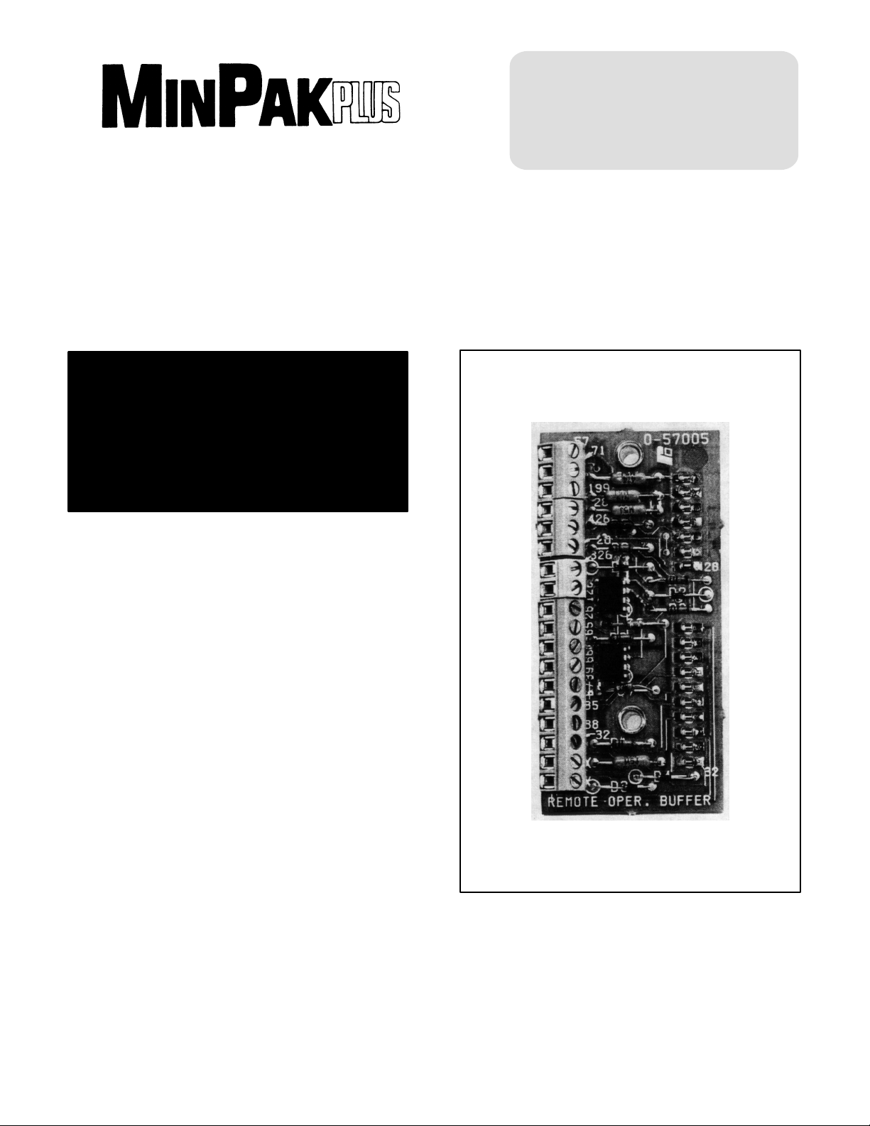
Figure 1 - Remote Operators Adapter Module
W/Terminal Markings
Page 2
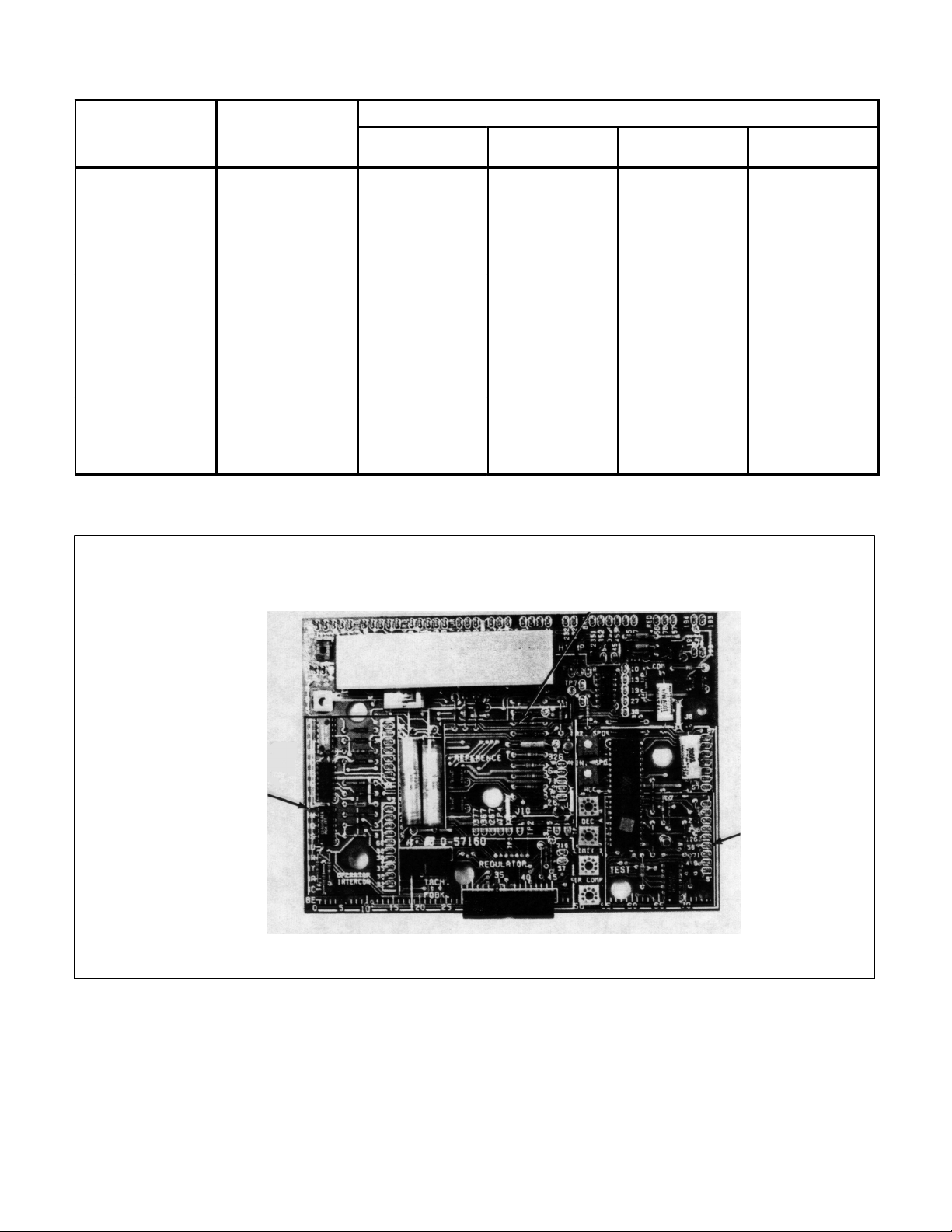
TABLE 1.A
MinPak Plus
Operator s
REMOTE OPERATOR CONTROL STATIONS
When Using a
Controller
With:
Basic features
(standard unidirecĆ
tional Station)
NEMA Type 4
Station with basic
features
ExplosionĆproof
Station with basic
features
Basic features plus
armature reversing
(standard reversing
Station)
NEMA Type 4 StaĆ
tion for reversing
ExplosionĆproof
Station for reversing
Specify
Functions Provided
'
Station
Model
Start/Stop
Rocker Switch
Speed Setting
Potentiometer
Run/Jog
Selector
Forward/Reverse
Selector
9C45 yes yes yes no
9C18 yes yes yes no
9C17 yes yes yes no
9C46 yes yes yes yes
9C19 yes yes yes yes
9C16 yes yes yes yes
REMOTE OPERATOR
ADAPTER MODULE
&
SWITCH
RECEIVER
MODULE
AREA
REFERENCE
AREA
Figure 2 Ċ Regulator Module Kit Locations
TEST
AREA
Page 3
INSTALLATION
WARNING
BEFORE ATTEMPTING TO INSTALL THE MINĆ
PAK PLUS MODIFICATION KIT, DISCONNECT
AND LOCK OUT ALL SOURCES OF INCOMING
POWER TO THE CONTROLLER.
Locate the area on the Regulator Module where the
1.
Remote Operator Adapter Module is to be
mounted. Place the Module in the proper orientaĆ
the edge with 10 holes should be aligned over
tion:
the 10 pins. (Refer to Figure 2). Carefully, slowly
and gently press the Module down on the pins
until it bottoms out. Use the 2 screws to secure
it.
2. Based on the specific control capability of the ReĆ
Operator Station chosen, select the required
mote
wires specified in T
3. Draw
the wires into
conduit. Then cut individual wires to lengths
cated
required for connection to the kit's terminal strip.
according to Figure 3.4, D
Wire
able 7.B, DĆ3937.
the Controller through the dedi
Ć3937.
WARNING
EXCESSIVE LENGTHS OF BARE WIRE COULD
CAUSE SHORTS AND/OR GROUNDS. STRIP
MINIMAL
INSULA
TION FROM EACH WIRE.
4. Visually inspect all wiring. Check wire placement
against diagrams. Look for grounds and shorts
caused
is
by broken
grounded.
insulation. Make sure the conduit
5. Attach the blank faceplate onto the cover if not alĆ
supplied. F
ready
vided
in Instruction Manual D
ollow installation instructions pro
Ć3977 MinP
ak Plus lo
Ć
Ć
cal operator station faceplate. Be sure to attach
ground
wire to cabinet door
.
DANGER
IT IS NECESSARY TO ATTACH THE FACTORY
CONTROLLER GROUND WIRE TO THE CONĆ
Ć
TROLLER CABINET DOOR VIA THE LOCAL
OPERATORS STATION FACEPLATE. PERĆ
SONAL INJURY MAY RESULT IF THIS PRACĆ
TICE IS NOT FOLLOWED.
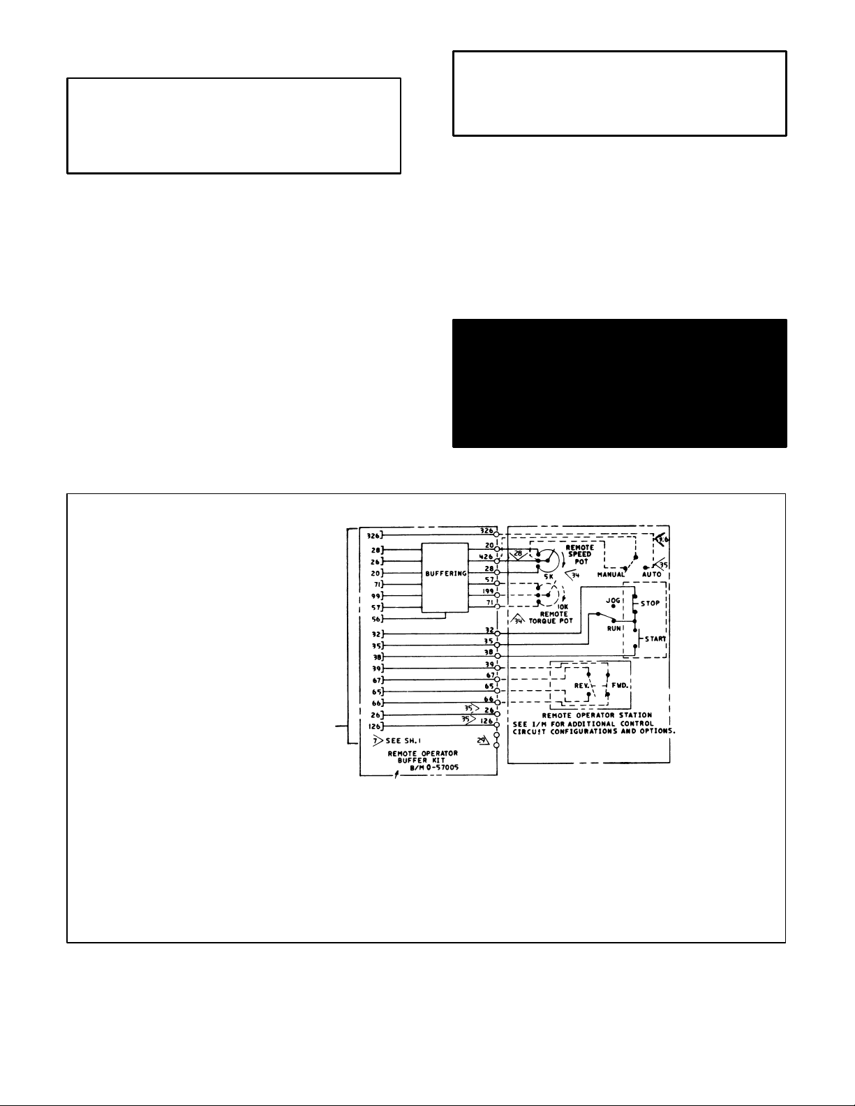
PRINTED CIRCUIT BOARD
NOT ARRANGED IN
ORDER SHOWN.
Figure 3 - Remote Operator Adapter Kit Schematic Diagram
35> When remote operator buffer kit is used with
switch receiver kit auto/manual switch is conĆ
nected to 326126 and 26 (instead of 326 426 and
POT wiper) on the remote operator butter kit terĆ
minal board. The respective pins mate with NC
232 and 32 on the switch receiver kit.
36 > If NOT using an auto/manual switch for automatic
operation only jumper terminals 426 and 326.
Page 4

U.S. Drives Technical Support
Tel: (1) 262.512.8176, Fax: (1) 262.512.2222, Email: support@drives.ra.rockwell.com, Online: www.ab.com/support/abdrives
Trademarks not belonging to Rockwell Automation are property of their respective companies.
Publication D-3979- 1999 Copyright © 1999 Rockwell Automation, Inc. All Rights Reserved. Printed in USA.
 Loading...