

Page 1
Installation Instructions
Bulletin 1405 (M610) Operating Instructions
Overview
The MiniPowermonitor (1405-M610) measures and displays voltage
and current parameters of low voltage AC power systems:
• Line-to-neutral and line-to-line voltages
• Instantaneous currents
• 15-minute averaged currents
• Peak currents
L-L
V
L1
L1-L2
L2
L2-L3
L3
L1-L3
V
L-N
A
15min
max
F
The MiniPowermonitor is a compact unit, with a 96 x 96 mm (3.78 x
3.78 in) front panel and a depth of only 65 mm (2.56 in).
The module’s display is arranged in 3 lines, each with 4 digits. The red
14 mm (0.55 in) high LED characters are easily readable from a
distance, in high ambient light conditions, and from acute viewing
angles. The measurement mode is indicated by 5 LED lamps that
show which parameter is displayed at that time.
Phase voltage and current measurements are made by sequential
scanning at 2 samples per second, so that 3 phase measurements are
made in 1.5 seconds. The updated average current value is displayed
approximately every 60 seconds, interjected into the cyclical sequence
of displayed parameters. Parameter values can be read out of
sequence, using the function (F) key on the front panel.
1 Publication 1405-IN001B-EN-P - October 2003
Page 2
2 Bulletin 1405 (M610) Operating Instructions
Installation
Only qualified personnel should install and wire this equipment. Refer
to the following safety guidelines prior to installation.
ATTENTION
ATTENTION
Only qualified personnel, following accepted safety
procedures, should install and wire the
MiniPowermonitor. Before beginning any work,
disconnect all sources of power and verify that they
are de-energized and locked out. Failure to follow
these instructions may result in personal injury or
death, property damage or economic loss.
Never open a current transformer (CT) secondary
circuit with primary current applied. Wiring between
the CTs and the MiniPowermonitor should include a
shorting terminal block in the CT secondary circuit.
Shorting the secondary with primary current present
allows other connections to be removed if needed.
An open CT secondary with primary current applied
produces a hazardous voltage, which can lead to
personal injury, death, property damage or economic
loss.
1. Install your MiniPowermonitor within a suitable enclosure. Make
sure the enclosure provides adequate clearance for ventilation
and wiring of the module.
dimensions and spacing guidelines for the MiniPowermonitor.
2. Determine your wiring mode and install wiring between the
MiniPowermonitor and your power system.
Connections on page 3 for more information.
3. Configure the current transformer (CT) ratios to match those
used in your power system connections.
Transformer Ratio Setting and Display Test on page 4 for more
information.
Refer to Dimensions on page 6 for
Refer to Input
Refer to Current
Grounding
MiniPowermonitors do not need to be grounded because of the
isolated enclosures. Follow all local requirements for grounding of PT
and CT secondaries.
Publication 1405-IN001B-EN-P - October 2003
Page 3
Bulletin 1405 (M610) Operating Instructions 3
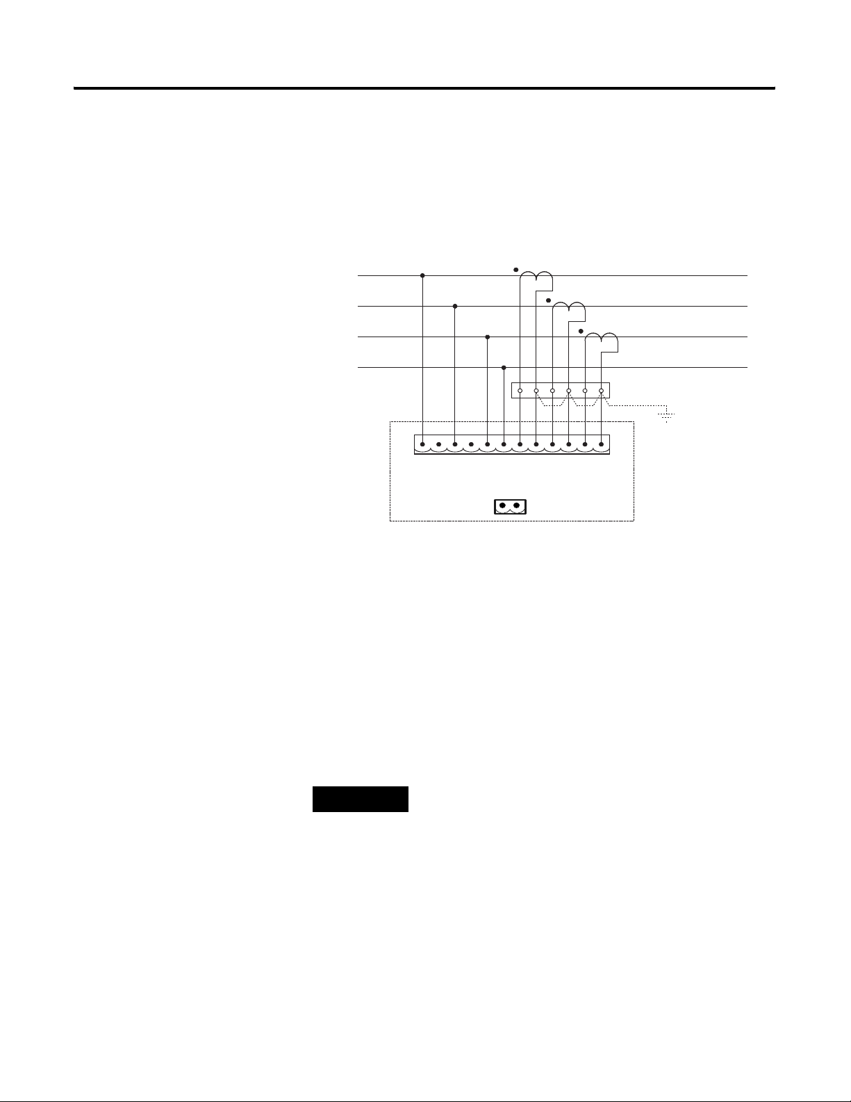
Input Connections
Input connections are at the rear, through a single 12-way plug-in
terminal block with spring clamps. The terminal block can accept wire
2
I2+
I2-
).
Shorting terminal block
(Wye connection optional)
Gnd
(if req'd)
I3-
I3+
sizes from 28 to 14 AWG (0.08 to 2.5 mm
L1
L2
L3
N
L1
L2
L3
N
I1-
I1+
M610
N
L1
The module uses industry-standard current transformers with a 5A
secondary for line current measurement.
• Internal shunt resistance for 5A current transformers: 0.01 ohm.
Aux Supply: With this option, instrument power is supplied by a
separate 120V or 240V line, independent of the measured power lines.
A second connector block (2-pin, spring-clamp terminals type) is
added at the rear with this option.
TIP
Terminals 2 and 4 (counting from left to right) are
not used. No connections should be made to these
terminals.
A unit with the 120V supply option is not designed to operate on
240V or any other voltage. Likewise, a unit with the 240V supply
option is not designed to operate on 120V or any other voltage. Units
designed for 400V and 480V operation do not have an auxiliary
supply connection and receive power from the measurement line.
Ensure that each unit is properly supplied with a power source that
matches the voltage designation of your unit.
Publication 1405-IN001B-EN-P - October 2003
Page 4
4 Bulletin 1405 (M610) Operating Instructions
L 1
L1 - L2
L 2
L1 - L3
L 3
L2 - L3
L 1
L1 - L2
L 2
L1 - L3
L 3
L2 - L3
Current Transformer Ratio Setting and Display Test
To select one of the pre-programmed standard current transformer
V
L- L
ratios, start with the module switched-off. Press and hold the function
“F” key while switching on the power, and for about 3 additional
V
L- N
seconds.
A
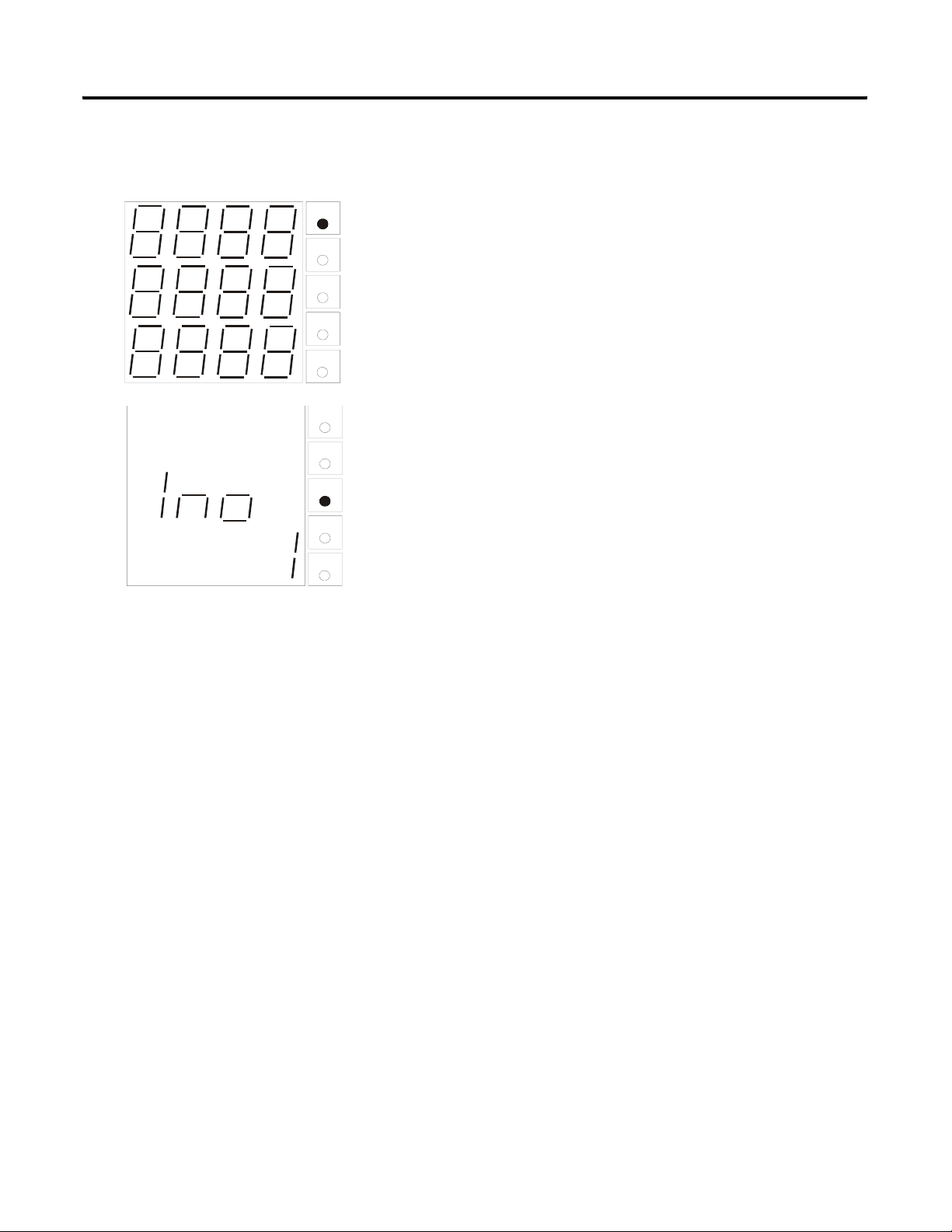
All segments of the LED displays and all the LED lamps light up one
after the other in rapid sequence to confirm the integrity of the
15
min
displays.
Max
Press the function “F” key again to initiate the current transformer
ratio setting routine. When it is pressed once, the value “1” is
V
L- L
displayed on the third line of the display. This is the first in the series
of industry-standard current ratio values that are pre-programmed in
V
L- N
the 1405-M610. It is indicated as the nominal value of the line current
(I
nominal
A
15
min
Pressing the function “F” key repeatedly steps the displayed value
through each successive standard current transformer ratios. The
Max
transformer ratio is I
transformer secondary rating.
values of I
).
nominal
:
nominal
:1 or I
nominal
:5, depending on the current
You may select from the following
(1)
1 / 2
/ 5 / 10 / 15 / 20 / 25 / 30 / 40 / 50 / 60 / 75 / 80 / 100 / 125
/ 150 / 200 / 250 / 300 / 400 / 500 / 600 / 750 / 800 / 1000 / 1200 /
1250 / 1500 / 1600 / 1800 / 2000 / 2500 / 3000 / 4000.
Publication 1405-IN001B-EN-P - October 2003
(1)
The actual value is 2.5A
Page 5

L 1
L1 - L2
L 2
L2 - L3
L 3
L1 - L3
Bulletin 1405 (M610) Operating Instructions 5
When the desired value is reached, the module is switched off without
pressing the function key any further. The ratio is now set and
protected against power interruptions. Now whenever the module is
switched on, this pre-set value is used for measuring line currents.
The ratio setting in existence when the power is switched off is the
same value that is valid when the power is switched on again, without
pressing the function key.
Measuring Operation
After the module has been switched on, the software version is
V
L- L
displayed for three seconds, after which the module starts scanning,
L- N
V
measuring, and displaying the power line parameter values. It starts
with the parameter that was selected whenever the “n” function was
A
last invoked. If a parameter was being held on display using the “r”
15
min
function when the module was last switched off, the module displays
the present values of that same parameter.
Max
L 1
L1 - L2
L 2
L2 - L3
L 3
L1 - L3
L 1
L 1
L1 - L2
L1 - L2
L 2
L 2
L2 - L3
L2 - L3
L 3
L 3
L1 - L3
L1 - L3
L 1
L1 - L2
L 2
L2 - L3
L 3
L1 - L3
In its normal sequential display mode, the measured parameter values
are displayed in the following sequence:
V
L- L
L- N
V
A
15
min
• Line-to-line voltages
• Line-to-neutral voltages
• Instantaneous phase currents
• Average phase currents
Max
V
L- L
V
L- L
• Peak phase currents
Press and hold the function key (“F”) to select one of three functions.
The selected function is indicated by the left-most character of lowest
L- N
V
L- N
V
line, and interpreted as follows:
A
A
• ‘n’: Key pressed for 0 to 2 seconds: skips the present parameter,
15
min
15
min
Max
Max
and displays the next parameter
• ‘r’: Key pressed for 2 to 4 seconds: sequential display of
parameters, on/off
• ‘c’: Key pressed for 4 to 8 seconds: re-sets average and peak
V
L- L
L- N
V
A
current values
The present parameter can be skipped and any other parameter
displayed by manual stepping, even if the automatic sequencing
mode (‘r’) is active. Similarly the ‘c’ mode can be invoked at any time
15
min
to delete the existing average and peak current measurements.
Max
Publication 1405-IN001B-EN-P - October 2003
Page 6

6 Bulletin 1405 (M610) Operating Instructions
Dimensions
Specifications
Panel cut-outs should be 92 x 92 mm (3.6 x 3.6 in).
Table 1 Measured Parameters
Voltage V
Instantaneous Current
Average Current (15 min.)
Peak Current
Measuring Rate Approximately 2 measurements per second
Update Time 1.5 Seconds
/ V
L1 - L2
V
/ V
L1 - N
IL1 / IL2 / I
L2 - L3
L2 - N
L3
/ V
/ V
L3-L1
L3-N
Publication 1405-IN001B-EN-P - October 2003
Table 2 Digital Displays
Typ e 7 Segment LED, Red
Lines x Characters 3 x 4
Character Height 14 mm (0.55 in)
Table 3 General Parameters
Parameter Value
Nominal Voltage Per Catalog Version
Units with separate 120V or 240V supply: 600V
Units powered from 400V measurement line: 400V
Units powered from 480V measurement line: 480V
Voltage Range 0.8 V to 1.1V * (nominal voltage)
Current Range 0.0 A to 6.0 A
Page 7

Bulletin 1405 (M610) Operating Instructions 7
Table 3 General Parameters
Parameter Value
Temperature Coefficient < 0.01% / K
Input Impedance (Voltage Inputs) 2 Mohm (Lx to N)
Input Impedance (Current Inputs) 0.01 ohm at 5A
Overload Rating Voltage 110% (continuous)
Current 200% (continuous)
Frequency Range 47 to 63 Hz
Power Consumption 3W typical
Operating Temperature +5°C to +50°C (+41°F to +122°F)
Storage Temperature -20°C to +70°C (-4°F to +158°F)
Protection Class Enclosure IP 20 (IP 65 with optional protective
(1)
)
hood
Terminals IP 00
Weight Approximately 0.3 kg
Front Dimensions 96 mm x 96 mm (3.78 in x 3.78 in)
Breakdown Rating Per DIN 41700
Depth 65 mm (2.56 in)
Panel Mounting Spring Clamps
Agency Certifications UL, CE
(1)
The optional hood, catalog number 1405-PRO, can be ordered separately. Contact your Rockwell Automation
distributor for additional information.
Table 4 Measurement Accuracy and Range
Parameter Percent of Reading Nominal Value Operating Range Maximum Limit
Volts ±1% 240V rms 10V rms to 347V rms L-N
or 17V rms to 600V rms
400V rms L-N or 690V
rms L-L
L-L
Current ±1% 5 Amps 0.1 Amps to 6 Amps 10 Amps
Publication 1405-IN001B-EN-P - October 2003
Page 8

8 Bulletin 1405 (M610) Operating Instructions
Product Approvals
UL/CUL
cULus Listed, File E96956, per UL508, the Standard for Industrial
Control Equipment.
CE Certification
If this product bears the CE marking, it is approved for installation
within the European Union and EEA regions. It has been designed to
meet the following directives.
EMC Directive
This product is tested to meet Council Directive 89/336/EEC
Electromagnetic Compatibility (EMC) and the following standards, in
whole, documented in a technical construction file:
• EN 50081-2 - Generic Emission Standard, Part 2 - Industrial
Environment
• EN 61000-6-2 - Generic Immunity Standard, Part 2 - Industrial
Environment.
This product is intended for use in an industrial environment.
Low Voltage Directive
This product is tested to meet Council Directive 73/23/EEC Low
Voltage, by applying the safety requirements of EN/IEC 61010-1.
This equipment is classified as open equipment and must be installed
(mounted) in an enclosure during operation as a means of providing
safety protection.
International Standard IEC 529 / NEMA / UL 508 Degree of
Protection
The MiniPowermonitor is rated as IP10 degree of protection per
International Standard IEC 529. It is considered an open device per
NEMA and UL 508.
Publication 1405-IN001B-EN-P - October 2003
Page 9

Catalog Number Explanation
Bulletin 1405 (M610) Operating Instructions 9
1405-M610-400-1A
Bulletin Number
1405 = MiniPowermonitor
1
- 120V and 240V connections are via a separate connection
2
- 400V and 480V connections are via the measurement line
Device Category
M610 = Volt and
Amp Meter
Power Supply
Voltage
No Designator =
120V 60 Hz
120 = 120V 60 Hz
240 = 240V 60 Hz
400 = 400V 50 Hz
480 = 480V 60 Hz
Current Input
1A = 1A current
inputs
1
No Designator =
5A current inputs
1
2
2
Publication 1405-IN001B-EN-P - October 2003
Page 10

10 Bulletin 1405 (M610) Operating Instructions
Publication 1405-IN001B-EN-P - October 2003
Page 11

Bulletin 1405 (M610) Operating Instructions 11
Publication 1405-IN001B-EN-P - October 2003
Page 12

Rockwell Automation Support
Rockwell Automation provides technical information on the web to assist you in using our products. At
http://support.rockwellautomation.com, you can find technical manuals, a knowledge base of FAQs, technical and
application notes, sample code and links to software service packs, and a MySupport feature that you can customize
to make the best use of these tools.
For an additional level of technical phone support for installation, configuration and troubleshooting, we offer
TechConnect Support programs. For more information, contact your local distributor or Rockwell Automation
representative, or visit http://support.rockwellautomation.com.
Installation Assistance
If you experience a problem with a hardware module within the first 24 hours of installation, please review the
information that's contained in this manual. You can also contact a special Customer Support number for initial help
in getting your module up and running:
United States 1.440.646.3223
Monday – Friday, 8am – 5pm EST
Outside United States Please contact your local Rockwell Automation representative for any technical support issues.
New Product Satisfaction Return
Rockwell tests all of our products to ensure that they are fully operational when shipped from the manufacturing
facility. However, if your product is not functioning and needs to be returned:
United States Contact your distributor. You must provide a Customer Support case number (see phone number
above to obtain one) to your distributor in order to complete the return process.
Outside United States Please contact your local Rockwell Automation representative for return procedure.
Publication 1405-IN001B-EN-P - October 2003 12 PN 40055-219-01(2)
Supersedes Publication 1405-IN001A-EN-P - July 2003 Copyright © 2003 Rockwell Automation, In c. All rights reserved. Printed in the U.S.A.
 Loading...