

Page 1
Installation Instructions
VersaView 1200P Integrated Display Computers for Hazardous Locations
Catalog Numbers 6183H-12FP, 6183H-12FPDC, 6183H-12NPDC, 6183H-2P,
6183H-2PDC, 6181H-2PXPHDC
Topic Page
Important User Information 2
European Union Directive Compliance 3
Hazardous Locations 3
Enclosures 5
Environmental Considerations 6
Operating Systems 7
Multilingual User Interface CD Pack 7
Before You Begin 8
Install the Computer 8
Mounting Clearances 9
Mounting Dimensions 10
Panel Mounting Guidelines 11
Install the Computer in a Panel 11
Connect a Keyboard and Pointing Device 13
Connect Peripheral Devices 13
Control Drawing - Class I Division 2 and Zone 2 14
Connect ac Power 17
Connect dc Power 18
Connect to the Network 19
Battery Information 19
Backlight Assembly Disposal 19
Ship or Transport the Product 20
Specifications 21
Additional Resources 22
Publication 6183H-IN001E-EN-P - July 2007
Page 2
2 VersaView 1200P Integrated Display Computers for Hazardous Locations
Important User Information
Solid state equipment has operational characteristics differing from those of electromechanical equipment.
Safety Guidelines for the Application, Installation and Maintenance of Solid State Controls (publication
SGI-1.1 available from your local Rockwell Automation sales office or online at
http://literature.rockwellautomation.com
equipment and hard-wired electromechanical devices. Because of this difference, and also because of the
wide variety of uses for solid state equipment, all persons responsible for applying this equipment must
satisfy themselves that each intended application of this equipment is acceptable.
In no event will Rockwell Automation, Inc. be responsible or liable for indirect or consequential damages
resulting from the use or application of this equipment.
The examples and diagrams in this manual are included solely for illustrative purposes. Because of the many
variables and requirements associated with any particular installation, Rockwell Automation, Inc. cannot
assume responsibility or liability for actual use based on the examples and diagrams.
No patent liability is assumed by Rockwell Automation, Inc. with respect to use of information, circuits,
equipment, or software described in this manual.
Reproduction of the contents of this manual, in whole or in part, without written permission of Rockwell
Automation, Inc., is prohibited.
Throughout this manual, when necessary, we use notes to make you aware of safety considerations.
) describes some important differences between solid state
WARNING
IMPORTANT
ATTENTION
SHOCK HAZARD
BURN HAZARD
Identifies information about practices or circumstances that can cause an explosion in
a hazardous environment, which may lead to personal injury or death, property
damage, or economic loss.
Identifies information that is critical for successful application and understanding of
the product.
Identifies information about practices or circumstances that can lead to personal injury
or death, property damage, or economic loss. Attentions help you to identify a hazard,
avoid a hazard, and recognize the consequences.
Labels may be on or inside the equipment, for example, a drive or motor, to alert
people that dangerous voltage may be present.
Labels may be on or inside the equipment, for example, a drive or motor, to alert
people that surfaces reach dangerous temperatures.
Publication 6183H-IN001E-EN-P - July 2007
Page 3
VersaView 1200P Integrated Display Computers for Hazardous Locations 3
European Union Directive Compliance
This computer meets the European Union Directive requirements when installed
within the European Union or EEA regions and has the CE mark. See http://ab.com
for declarations of conformity, certificates, and other certification details.
ATTENTION
ATTENTION To comply with EN 55024, the Ethernet port LAN cable must be less than 30 m
This product is intended to operate in an industrial or control room
environment, which utilizes some form of power isolation from the public
low-voltage mains. Some computer configurations may not comply with the EN
61000-3-2 Harmonic Emissions standard as specified by the EMC Directive of
the European Union. Obtain permission from the local power authority before
connecting any computer configuration that draws more than 75 W of ac power
directly from the public mains.
(98.42 ft), and it must only be used indoors (not exit the building at any point).
All other I/O cables must be less than 3 m (9842 ft), and must only be used
indoors.
Hazardous Locations
This equipment is suitable for:
• Class I, Zone 2, Group IIC.
• Class I, Division 2, Groups A, B, C, D.
• nonhazardous locations.
The dc powered touch-screen and non-display units are additionally suitable for
European Zone 2 applications as defined by EU Directive 94/9/CE (ATEX) as it
relates to Category 3 equipment intended for use in potentially explosive
atmospheres given in Annex II of this directive per EN60079-15:2003.
The units are rated:
• II 3G EEx nL IIC T4.
• 0 °C ≤ T
• Certificate: DEMKO 06 ATEX 0627219 X.
amb
≤ 50 °C.
Publication 6183H-IN001E-EN-P - July 2007
Page 4

4 VersaView 1200P Integrated Display Computers for Hazardous Locations
The following statement applies to use in hazardous locations.
WARNING
Explosion Hazard
Substitution of components may impair suitability for hazardous locations.
Do not disconnect equipment unless power has been switched off and area
is known to be nonhazardous.
Do not connect or disconnect components unless power has been switched
off.
All wiring must comply with N.E.C., NFPA 70 articles 501.4(B), 505.15(C) as
appropriate and in accordance with the authority having jurisdiction.
Peripheral equipment must be suitable for the location it is used in.
For European Zone 2 and Canadian Ex applications, provisions shall be
made to prevent the rated applied voltage from being exceeded by
transient disturbances of more than 40%.
For European Zone 2 and Canadian Ex applications, non-display computers
must be mounted completely within an enclosure rated IP54 minimum.
Computers with displays must be mounted through the wall or door of an
enclosure rated IP54 minimum. Computers with displays support
enclosures rated up to IP66.
These devices shall be properly connected to ground (protective earth) in
the final application.
Refer to control drawing information in this document for allowable circuit
parameters, in Class I, Division 2 applications. Do not use the USB and PS2
ports in European Zone 2 and Canadian Ex applications unless the area is
known to be nonhazardous.
The computers have a temperature code of T4 135 °C (275 °F) when operating in
50 °C (122 °F) maximum ambient temperature. Do not install the computer in
environments where the explosive atmosphere (for example, gas) has an ignition
temperature less than 135 °C (275 °F).
Publication 6183H-IN001E-EN-P - July 2007
Page 5

VersaView 1200P Integrated Display Computers for Hazardous Locations 5
Enclosures
Mount the computer in a panel or enclosure to protect the internal circuitry.
Versions with a gasketed bezel meet NEMA Type 4, 12, and IEC IP66 only when
mounted in a panel or enclosure having an equivalent rating. Versions with an
ungasketed bezel meet NEMA Type 1.
ATTENTION
This equipment is intended for use in a Pollution Degree 2 industrial
environment, in overvoltage Category II applications (as defined in IEC
publication 60664-1), at altitudes up to 2000 m (6562 ft) without derating. The
enclosure door must be closed.
This equipment is considered Group 1, Class A industrial equipment according
to IEC/CISPR Publication 11. Without appropriate precautions, there may be
potential difficulties ensuring electromagnetic compatibility in other
environments due to conducted as well as radiated disturbance.
Operating the capacitive touchscreen version in a high noise environment may
cause the touchscreen to respond slowly to touch inputs, or may cause the
position of the screen cursor to drift.
This equipment is supplied as "open type" equipment. It must be mounted
within an enclosure that is suitably designed for those specific environmental
conditions that will be present and appropriately designed to prevent personal
injury resulting from accessibility to live parts. The interior of the enclosure
must be accessible only by the use of a tool. Subsequent sections of this
publication may contain additional information regarding specific enclosure
type ratings that are required to comply with certain product safety
certifications.
In addition to this publication, see:
• Industrial Automation Wiring and Grounding Guidelines, for additional
installation requirements, Allen-Bradley publication 1770-4.1.
• NEMA Standards publication 250 and IEC publication 60529, as applicable,
for explanations of the degrees of protection provided by different types of
enclosure.
Publication 6183H-IN001E-EN-P - July 2007
Page 6

6 VersaView 1200P Integrated Display Computers for Hazardous Locations
Environmental Considerations
Follow these guidelines to help ensure that the computer provides safe and reliable
service.
• Make sure that sufficient space is available around air inlets and outlets to
provide the circulation necessary for cooling. Never allow air passages to
become obstructed.
• Allow enough room within the enclosure for adequate ventilation. The
ambient temperature around the computer must be between 0…50 °C
(32…122 °F). Also consider heat produced by other devices in the
enclosure. You may need a user-supplied fan, heat exchanger, or air
conditioner to meet this condition in some installations.
TIP
IMPORTANT
• Make sure that the humidity of the ambient air will not exceed specified
limits. In very dry environments, static charges build up very readily. Proper
grounding of the equipment through the ac power cord can help reduce the
likelihood of static discharges, which may cause shocks and damage
electronic components.
• Leave the computer’s enclosure or cover in place at all times during
operation. The cover affords protection against high voltages inside the
computer and inhibits radio-frequency emissions that might interfere with
other equipment.
Remember that heat rises. The temperature at the top of an enclosure is
often much higher than the rest of the enclosure if air is not circulating.
This product is designed to operate at a range of temperature extremes.
However, it is not good design practice to continuously operate the computer
at the highest end of the specified temperature range.
While the product will operate at its highest specified temperature, the overall
life span of any electronic device is shortened when it operates at its highest
rated temperature.
Publication 6183H-IN001E-EN-P - July 2007
Page 7

VersaView 1200P Integrated Display Computers for Hazardous Locations 7
Operating Systems
The computers are shipped with one of these operating systems:
• Windows 2000 Professional, Service Pack 4 with Update Rollup 1
• Windows XP Professional, Service Pack 2b
No operating system updates have been applied to the factory image beyond the
service packs.
For your convenience, the I386 source directory for Microsoft Windows is on the
system drive of your computer off the root directory, C:\I386. This allows for easy
removal and addition of Windows components.
Computers with rotating-media hard drives include a recovery partition on the
system drive containing the original factory image. You can use the supplied System
Accessories/Cloning CD to restore the operating system from the recovery partition,
create a new recovery image, and create bootable external recovery media.
Refer to the Cloning Utility documentation, publication 6000-TD001, for
instructions. You can view or download publications at
http:\\literature.rockwellautomation.com.
Computers with solid state drives have been customized to accommodate the
unique properties of the solid state drive. Some of the pre-installed customizations
include:
• no paging file.
• system restore set to zero and disabled.
• DLLCACHE directory emptied.
Computers with solid state hard drives do not contain a recovery partition. If
additional drive space is required, copy the I386 directory to external media; then
delete the I386 directory from C:\I386, which is approximately 400 MB.
To obtain the original factory image on bootable external recovery media, which
also includes the I386 source directory, contact your local technical support center.
Multilingual User Interface CD Pack
The Microsoft Multilingual User Interface (MUI) CD Pack contains a collection of
different language sets that can be installed into the operating system. MUI packs
are available for all Windows XP operating systems and provide a localized start
menu and system icons support.
The instructions for installing MUI languages on your computer are supplied with
the MUI CD Pack.
Publication 6183H-IN001E-EN-P - July 2007
Page 8

8 VersaView 1200P Integrated Display Computers for Hazardous Locations
Before You Begin
Before unpacking your new computer, inspect the shipping carton for damage. If
damage is visible, immediately contact the shipper and request assistance.
Otherwise, proceed with unpacking.
Keep all the original packaging for the computer in case you need to return the
computer for repair. Both the inner and outer packing cartons should be used to
ensure adequate protection for any units returned for service.
Parts List
The computer is shipped with these items.
• Ten mounting clips, except for the 1200P non-display computer
• Power cord, ac (when appropriate)
• VersaView Accessories CD
• VersaView Support CD
• Microsoft Multilingual User Interface (MUI) CD Pack
This CD pack is not included with VersaView computers containing the
Windows 2000 operating system.
Required Tools
In addition to the tools required to make the cutout, you will also need a #2 Phillips
screwdriver.
Install the Computer
Before installing the computer in a panel, review:
• mounting clearances.
• mounting dimensions.
• panel mounting guidelines.
Publication 6183H-IN001E-EN-P - July 2007
Page 9

VersaView 1200P Integrated Display Computers for Hazardous Locations 9
Mounting Clearances
Allow adequate space around the computer for mounting, air flow, and
maintenance. The figure below shows recommended minimum clearances to other
components within the rack or enclosure.
ATTENTION Do not operate this computer within a confined space using clearances
that are less than those show below unless adequate ventilation or other
cooling methods are used to lower the air temperature within the
enclosure.
Mounting Clearances
Top Clearance
50 mm (2 in.) for air flow
Back Clearance
25 mm (2 in.)
Bottom Clearance
102 mm (4 in.) for air flow
and connections
Left Side Clearance
50 mm (2 in.) for air flow
Right Side Clearance
50 mm (2 in.) for air flow
Publication 6183H-IN001E-EN-P - July 2007
Page 10

10 VersaView 1200P Integrated Display Computers for Hazardous Locations
Mounting Dimensions
Review the product dimensions to estimate the clearance necessary for computer
installation. The product dimensions are expressed in millimeters and (inches).
1200P Integrated Display Computer
Top view
320 (12.60)
281 (11.079)
349 (13.75)
279 (10.99)
Front view
1200P Non-Display Computer
Top view
Back view
240 (9.46)
190.5 (7.51)
281 (11.079)
343 (13.51)
317.5 (12.51)
8.00 (0.31)
175.9 (6.93)
251 (9.89)
Side view
Side view
144.9 (5.70)
2 (0.078)
239.1 (9.41)
Publication 6183H-IN001E-EN-P - July 2007
Page 11
VersaView 1200P Integrated Display Computers for Hazardous Locations 11
Panel Mounting Guidelines
Observe the following precautions when installing the computer in a panel.
• Confirm that there is adequate space behind the panel.
• Supporting panels should be at least 14 gauge to ensure proper sealing
against water and dust and to provide proper support. The mounting
hardware supplied accommodates panels up to 6 mm (0.24 in.) thick.
IMPORTANT
Supporting panels must be cut to specifications before installation.
Install the Computer in a Panel
ATTENTION
Follow these directions to install the computer in a panel using mounting clips.
1. Cut an opening in the panel using the appropriate panel cutout dimensions.
2. Make sure the sealing gasket is properly positioned on the computer.
IMPORTANT
3. Place the computer in the panel cutout.
Disconnect all electrical power from the panel before making cutout. Make
sure the area around the panel cutout is clear. Take precautions so that metal
cuttings do not enter any components that are already installed in the panel.
Failure to follow these warnings may result in personal injury or damage to the
panel components.
This gasket forms a compression type seal. Do not use sealing compounds.
Publication 6183H-IN001E-EN-P - July 2007
Page 12

12 VersaView 1200P Integrated Display Computers for Hazardous Locations
4. Install the mounting clips.
The mounting clips slide into the slots on the top, bottom and sides of the
computer.
5. Gradually tighten the clips one at a time around the bezel using the specified
sequence.
Note that the sequence begins with the center clips and continues to the
corner clips.
1109
5
Tor qu e
Sequence
4
278
3
6
Repeat this process at least three times until the clips are hand-tight and the
gasket is compressed uniformly against the panel.
6. Tighten mounting clips to a torque of 1.1 Nm (10 lb-in) in the sequence
shown above. Do not over-tighten.
ATTENTION
Tighten mounting clips to a torque of 1.1 Nm (10 lb-in) to provide a proper
seal and prevent damage to the computer. Rockwell Automation assumes
no responsibility for water or chemical damage to the terminal or other
equipment within the enclosure because of improper installation.
Publication 6183H-IN001E-EN-P - July 2007
Page 13

VersaView 1200P Integrated Display Computers for Hazardous Locations 13
Connect a Keyboard and Pointing Device
A keyboard and/or mouse can be connected to the computer using either the USB
or PS/2 connectors. The USB and PS/2 ports should not be used unless the area is
known to be non-hazardous. Access to the ports is restricted by a cover that should
be kept closed when the area could be hazardous.
Keyboard and Pointing Device
1200P Series B shown
with USB and PS/2
access covers opened.
Connect Peripheral Devices
• When connecting peripheral devices to the COM, Printer, or VGA ports on
the unit, secure the connected devices with screws.
• When connecting a LAN cable, make sure the cable is fully inserted and the
latch engaged.
WARNING
• Access to the USB and PS/2 ports is restricted by a cover for hazardous
location security.
In addition, nonincendive field wiring circuit parameters are provided with
the control drawing on page 14.
When connecting a LAN cable, make sure the cable is fully inserted and
the latch engaged. Failure to do so, could result in an electrical arc. This
could cause an explosion in a hazardous location.
Publication 6183H-IN001E-EN-P - July 2007
Page 14

14 VersaView 1200P Integrated Display Computers for Hazardous Locations
Control Drawing - Class I Division 2 and Zone 2
The following control drawing is provided in accordance with the National
Electrical Code, Article 500 (Class I, Division 2, Groups A, B, C, D and Class I,
Zone 2, Group IIC).
1200P Control Drawing for National Electrical Code
Associated Nonincendive
Field Wiring Apparatus
VersaView 1200P Host Product
USB Port
USB Port
PS2 Mouse Port
PS2 Keyboard Port
Nonincendive
Field Wiring Apparatus
USB Peripheral Device
USB Peripheral Device
PS2 Mouse
PS2 Keyboard
VersaView 1200P USB and PS2 Port Circuit Parameters
Parameter Value Parameter Definition
V
oc (USB)
V
oc (PS2)
I
sc (USB)
I
sc (PS2)
C
a (USB)
C
a (PS2)
L
a (USB)
L
a (PS2)
5.25V dc Open circuit voltage of each host USB or PS2 port.
1.0 A Maximum output current of each host USB port.
2.1 A Maximum output current of the host PS2 port.
20 µF This value is the maximum total capacitance that can be
connected to each USB port when used singly or together.
The total capacitance of each USB peripheral and its cable
must not exceed the indicated value.
20 µF This value is the maximum total capacitance that can be
connected to a single PS2 port when used alone, or the sum
of the total capacitance connected to both PS2 ports when
used simultaneously. If multiple PS2 peripheral devices are
used, the total capacitance of all devices and their cables
must not exceed the indicated value.
3.11 µH This value is the maximum total inductance that can be
connected to each USB and PS2 port. The total inductance
of each peripheral device and its cable must not exceed the
the indicated value.
Publication 6183H-IN001E-EN-P - July 2007
Page 15

VersaView 1200P Integrated Display Computers for Hazardous Locations 15
Required Circuit Parameters for USB and PS2 Peripheral Devices
Parameter Value Parameter Definition
V
max (USB)
V
max (PS2)
5.25V dc
(minimum)
Maximum applied voltage rating of each peripheral device. V
peripheral shall be greater than or equal to V
in the VersaView 1200P
oc (USB)
USB and PS2 Port Circuit Parameters table on page 14.
of each USB
max
I
max (USB)
I
max (PS2)
C
i (USB)
C
i (PS2)
L
i (USB)
L
i (PS2)
1.0 A
(minimum)
2.2 A
(minimum)
V
max (per ipheral)
Maximum current to which each USB peripheral device can be subjected. I
of each USB peripheral shall be greater than or equal to I
VersaView 1200P USB and PS2 Port Circuit Parameters table on page 14.
I
max (USB peripheral)
Maximum current to which each PS2 peripheral device can be subjected. I
of each PS2 peripheral shall be greater than or equal to I
VersaView 1200P USB and PS2 Port Circuit Parameters table on page 14.
I
max (PS2 peripheral)
≥ V
oc (USB)
≥ I
≥ I
sc (USB)
sc (PS2)
and/or V
oc (PS2) ,
as appropriate.
sc (USB)
sc (PS2)
in the
max
max
in the
20 µF Maximum allowed total capacitance of each separate USB peripheral device
and its associated cable. C
of its associated cable shall be less than or equal to C
of each separate USB peripheral device and C
i
in the VersaView
a (USB)
cable
1200P USB and PS2 Port Circuit Parameters table on page 14.
C
i ( USB)
+ C
cable (USB)
≤ C
a (USB)
20 µF Maximum allowed total capacitance of all simultaneously connected PS2
peripheral devices and their associated cables. The sum of C
simultaneously connected PS2 peripheral devices and C
associated cables shall be less than or equal to C
a (PS2)
of all
i
of their
cable
in the VersaView 1200P
USB and PS2 Port Circuit Parameters table on page 14.
+ C
(C
i
cable) PS2 / 1 + (Ci
+ C
cable) PS2 / 2
≤ C
a (PS2)
3.11 µH Maximum allowed total inductance of each peripheral device and its
associated cable. The sum of L
of each peripheral device and L
i
associated cables shall be less than or equal to L
a (USB) or La (PS2)
cable
of its
as
appropriate in the VersaView 1200P USB and PS2 Port Circuit Parameters table
on page 14.
+ L
(L
i
(Li + L
(Li + L
(Li + L
cable) USB1
cable) USB2
cable) PS2/1
cable) PS2/2
≤ L
≤ L
≤ L
≤ L
a (USB)
a (USB)
a (PS2)
a (PS2)
Publication 6183H-IN001E-EN-P - July 2007
Page 16

16 VersaView 1200P Integrated Display Computers for Hazardous Locations
Application Information
The circuit parameters of associated field-wired apparatus for use in hazardous
locations shall be coordinated with the host product such that their combination
remains nonincendive. The VersaView 1200P computer, and the PS2 and USB
peripheral devices shall be treated in this manner.
The circuit parameters of the VersaView 1200P computer’s USB and PS2 ports are
given in the VersaView 1200P USB and PS2 Port Circuit Parameters table. The
VersaView 1200P computer provides two separately powered USB ports and two
parallel powered PS2 ports.
The USB and PS2 peripheral devices and their associated cabling shall have circuit
parameters with the limits given in the Required Circuit Parameters for USB and PS2
Peripheral Devices table for them to remain nonincendive when used with the
VersaView 1200P computer’s USB and PS2 ports.
For the comparison of C
o (PS2)
and C
connected PS2 peripheral devices and their associated cables C
For the comparison of C
o (USB)
and C
connected USB peripheral device and its associated cable C
For the comparison of L
o (USB)
with L
, use the sum of the capacitance of all
i (PS2)
.
cables
, use the capacitance of each individual
i (USB)
.
cable
i (USB)
and L
o (PS2)
with L
i (PS2)
, use the
inductance of each individual peripheral device and its associated cable for Li.
If cable capacitance and inductance are not known, the following values may be
used:
C
= 60 pF/ft (197 pF/m)
cable
= 0.20 µH/ft (0.66 µH/ft)
L
cable
Publication 6183H-IN001E-EN-P - July 2007
Page 17

VersaView 1200P Integrated Display Computers for Hazardous Locations 17
Connect ac Power
A standard IEC 320 power cord provides power to the computer. The power supply
input accepts 120/240V ac. The power supply is autoswitching.
Retainer Clip
1200P Only:
You may need to remove the ac retainer
clip prior to installing the unit into a
panel cut-out. Attach the clip after
installing the unit.
ATTENTION
Select the power source carefully before connecting your computer.
The power cord must be connected to a terminal block and earth ground.
Failure to follow this warning could result in severe electrical shock.
Installing the computers in a panel, enclosure or rack that is already
connected to Earth ground will satisfy this requirement. Otherwise,
2
connect your computer to Earth ground using a 1.31 mm
(16 AWG) or
larger external wire.
The ground wire should have green insulation with a yellow stripe for easy
identification.
The power source selected must have its own disconnect. Do not connect
the computer to a supply that is connected to the main electrical
disconnect.
To prevent problems resulting from power surges or unexpected power
failure, you should protect the outlet with its own fuses or circuit breakers,
as well as an Uninterruptible Power Supply (UPS) system.
Always shut down the operating system prior to removing power to
minimize performance degradation and operating system failures.
Publication 6183H-IN001E-EN-P - July 2007
Page 18
18 VersaView 1200P Integrated Display Computers for Hazardous Locations
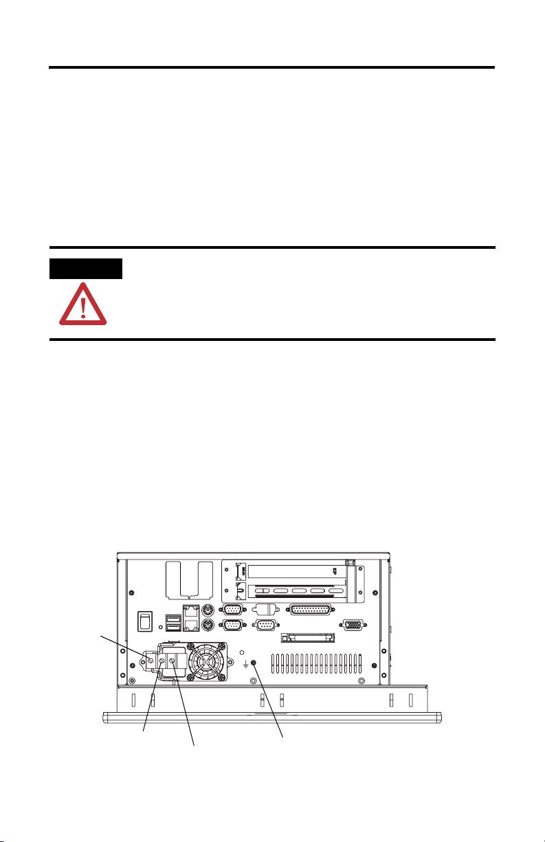
Connect dc Power
Computers with an integrated 24V dc power supply support these electrical ratings:
• 18…32V dc (24V dc nominal)
• 6.3 A at 24V dc
• 5.8 A at 24V dc (non-display dc product)
The power supply is internally protected against reverse polarity.
ATTENTION Use a Class 2/SELV (Safety Extra-Low Voltage) isolated and ungrounded power
supply as input power to the computer. This power source provides protection
so that under nominal and single fault conditions, the voltage between the
conductors and Functional Earth/Protective Earth does not exceed a safe value.
The terminals of the dc power supply are for factory wiring only. The suitability of
the connections shall be determined in the end use equipment.
When wiring to the dc power terminal block, use 0.823 mm
(18 AWG…14 AWG) stranded copper wire.
Follow these steps to connect dc power.
2
…2.08 mm2
1. Secure the dc power wires to the terminal block screws.
2. Secure the ground wire to the GND terminal screw.
3. Apply 24V dc power to the terminal.
GND
(Safety Ground)
V- (dc Negative)
V-
V+
V+ (dc Positive)
GND (Safety Ground Alternate Connection)
Publication 6183H-IN001E-EN-P - July 2007
Page 19

VersaView 1200P Integrated Display Computers for Hazardous Locations 19
Connect to the Network
The computers connect to an Ethernet network using CAT5 twisted pair Ethernet
cabling with RJ45 connectors.
IMPORTANT
To prevent performance degradation of Ethernet communication, do not subject
the computer or cables to extreme radiation or conducted high-frequency noise.
Proper cable routing and power conditioning is required to ensure reliable
Ethernet communication in an industrial environment. Rockwell Automation
recommends that you route all Ethernet cabling through dedicated metal
conduits. Installing ferrite bead filters at the cable ends may also improve
reliability.
Battery Information
The computer contains a battery to maintain CMOS settings and the real-time clock.
The battery is located in a battery holder on the computer’s motherboard. The
battery is not user serviceable.
WARNING
Do not dispose of battery in a fire or incinerator. Dispose of used batteries in
accordance with local regulations or manufacturer’s instructions.
For safety information on the handling and disposal of lithium batteries see
Guidelines for Handling Lithium Batteries, publication 1757-5.13
.
Backlight Assembly Disposal
ATTENTION
The backlight assembly in this unit contains mercury. At the end of its life, this
equipment should be collected separately from any unsorted municipal waste.
Publication 6183H-IN001E-EN-P - July 2007
Page 20

20 VersaView 1200P Integrated Display Computers for Hazardous Locations
Ship or Transport the Product
If you need to ship your computer via common carrier or otherwise transport it to
another location, you must first uninstall the unit from the panel and place it in its
original packing material.
ATTENTION
Do not ship or transport the product when it is installed in a machine, panel or
rack. Doing so may cause damage to the product. You must uninstall the
product and place in its original packing material before shipping. Rockwell
Automation is not responsible for damage incurred to a product that is shipped
or transported while installed in a machine, panel or rack.
Publication 6183H-IN001E-EN-P - July 2007
Page 21
VersaView 1200P Integrated Display Computers for Hazardous Locations 21
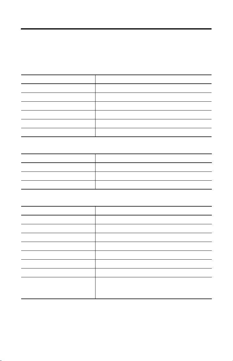
Specifications
VersaView 1200P Integrated Display, 6183H-12FP, 6183H-12FPDC, 6183H-12NPDC,
6183H-2P, 6183H-2PDC, 6181H-2PXPHDC
Attribute Value
Display description Active Matrix Color TFT
Display size 12.1 inch
Display area, approx. 246 x 185 mm (9.7 x 7.3 in.)
Resolution 800 x 600, 256K Color
Response time 15 ms (typical)
Touchscreen (optional) Projected capacitive
Mechanical Specifications
Attribute Value
Weight 9.2 kg (21 lb)
Dimensions, overall (H x W x D), approx. 279 x 349 x 176 mm (11.0 x 13.75 x 6.93 in.)
Cutout dimensions (H x W), approx. 254 x 324 mm (10.0 x 12.76 in.)
Environmental Specifications
Attribute Value
Temperature, operating 0…50 °C (32…122 °F)
Temperature, storage -20…60 °C (-4…140 °F)
Relative humidity 10%…90% without condensation
Shock, operating 15 g (1/2 sine, 11ms)
Shock, non-operating 30 g (1/2 sine, 11ms)
Vibration, operating 1.5 g Peak (10…500Hz)
Vibration, non-operating 2 g Peak (10…500Hz)
(1)
Ratings
1200P
1200P (6181H/6183H Non-display)
(1)
When installed in enclosure with an equivalent rating.
NEMA Type 4, 12, IEC IP66
NEMA Type 1
Publication 6183H-IN001E-EN-P - July 2007
Page 22

22 VersaView 1200P Integrated Display Computers for Hazardous Locations
Electrical Specifications
Attribute Value
Input voltage, ac 90…264V ac, autoranging
Line frequency 47…63 Hz
Power consumption, ac
1200P
1200P (6181H/6183H Non-display)
Input voltage, dc
1200P
1200P (6181H/6183H Non-display)
Power consumption, dc
1200P
1200P (6181H/6183H Non-display)
150 VA (1.5 A @ 100V rms, 0.63 A @ 240 V rms)
140 VA (1.4 A @ 100V rms, 0.58 A @ 240 V rms)
18…32V dc
150 W
140 W
Certifications
Certification
CE Marked for all applicable directives
c-UL-us UL 1604 recognized component, C-UL certified
C-Tick Australian Radiocommunications Act, compliant with:
RoHS compliant
ATEX Zone 2 Applicable to dc powered touch-screen and non-display units only.
(1)
See http://ab.com for declarations of conformity, certificates, and other certification details.
(1)
Value
LVD (73/23/EEC)
EMC (89/336/EEC)
UL-Listed Industrial Control Equipment for use in:
• Class I, Division 2, Groups A, B, C, D
• Class I, Zone 2, Group IIC
AS/NZS CISPR 11; Industrial Emissions
Additional Resources
For additional information on the VersaView computers, refer to VersaView
Integrated Display Computers User Manual, publication 6181P-UM001
You can view or download publications at
http://literature.rockwellautomation.com
. To order paper copies of technical
documentation, contact your local Rockwell Automation distributor or sales
representative.
.
Publication 6183H-IN001E-EN-P - July 2007
Page 23

Notes:
VersaView 1200P Integrated Display Computers for Hazardous Locations 23
Publication 6183H-IN001E-EN-P - July 2007
Page 24

Rockwell Automation Support
Rockwell Automation provides technical information on the Web to assist you in
using its products. At http://support.rockwellautomation.com
technical manuals, a knowledge base of FAQs, technical and application notes,
sample code and links to software service packs, and a MySupport feature that you
can customize to make the best use of these tools.
For an additional level of technical phone support for installation, configuration,
and troubleshooting, we offer TechConnect Support programs. For more
information, contact your local distributor or Rockwell Automation representative,
or visit http://support.rockwellautomation.com
.
Installation Assistance
If you experience a problem with a hardware module within the first 24 hours of
installation, please review the information that's contained in this manual. You can
also contact a special Customer Support number for initial help in getting your
module up and running.
, you can find
United States 1.440.646.3223
Outside United
States
Monday – Friday, 8am – 5pm EST
Please contact your local Rockwell Automation representative for any
technical support issues.
New Product Satisfaction Return
Rockwell tests all of its products to ensure that they are fully operational when
shipped from the manufacturing facility. However, if your product is not
functioning, it may need to be returned.
United States Contact your distributor. You must provide a Customer Support case number
Outside United
States
Allen-Bradley, VersaView, Rockwell Automation, and TechConnect are trademarks of Rockwell Automation, Inc.
Trademarks not belonging to Rockwell Automation are property of their respective companies.
Publication 6183H-IN001E-EN-P - July 2007 PN 41061-362-01(5)
Supersedes Pub lication 6183H-IN001D -EN-P - March 2007 Copyright © 20 07 Rockwell Automati on, Inc. All rights reser ved. Printed in the U.S.A.
(see phone number above to obtain one) to your distributor in order to
complete the return process.
Please contact your local Rockwell Automation representative for return
procedure.
 Loading...