

Page 1
Bulletin 1102C 400A / 600A Vacuum Contactor
AC Coil Replacement Instructions
(Cat 1102C-PK4D, -PK4A, -PK4N, -PK4B,
1102C-PK6D, -PK6A, -PK6N, -PK6B)
ATTENTION: To prevent electrical shock, disconnect from power source before installing or servicing. If coil failure is
suspected, check that secondary damage has not occurred that will render the contactor non-repairable.
Coil Replacement
1. Disconnect all power cables (or bus work) and all control wiring to the contactor.
2. Remove the contactor from its mounted location. The contactor is best serviced in the tabletop position.
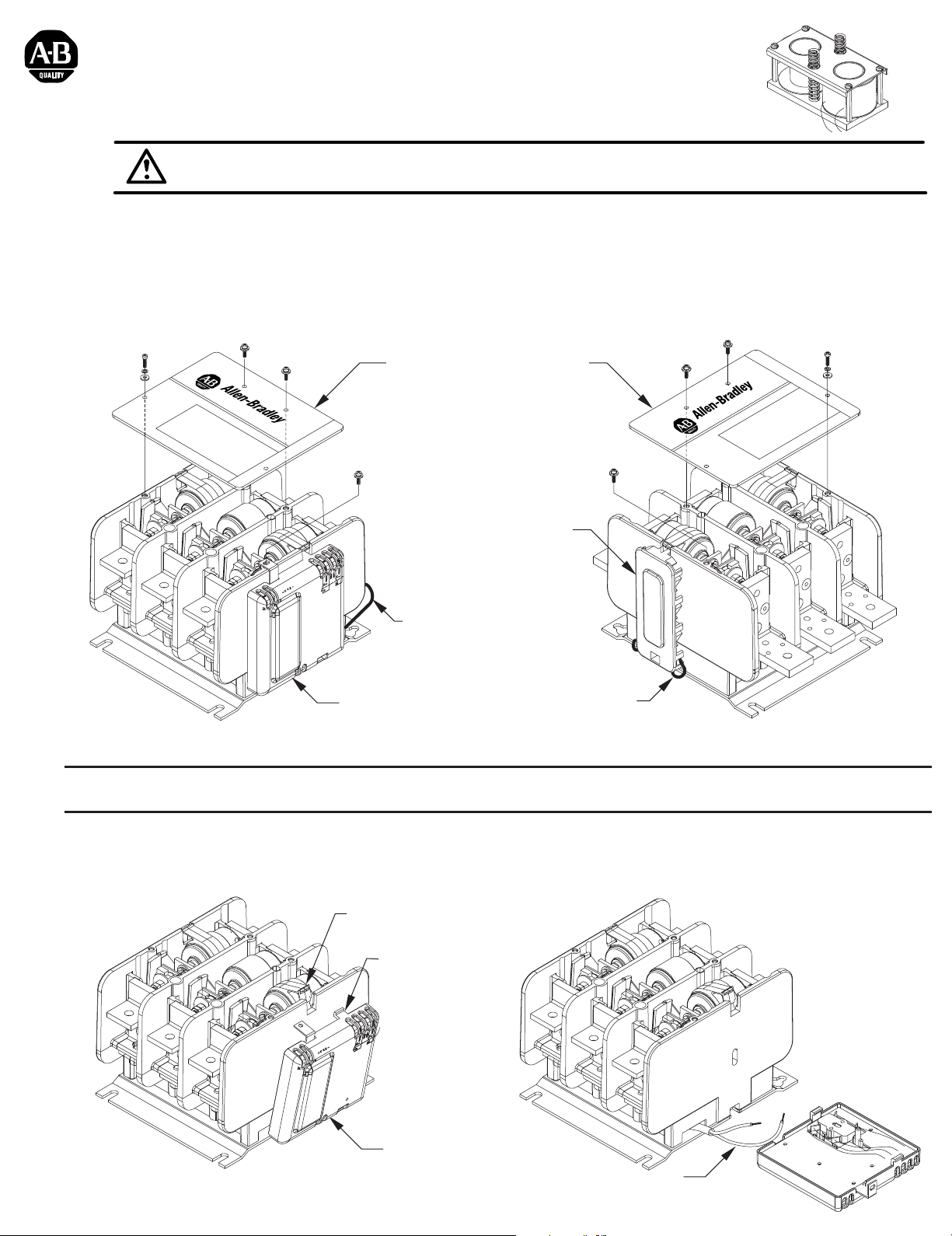
3. Disconnect the coil wire leads from the Control-Pak or Auxiliary (Figure 2B).
4. Remove the cover attachment hardware from the contactor and remove the cover (Figure 1).
CoverCover
VA
CUUM CONT
A
C
TO
R
VA
C
UUM
CONTAC
R
O
T
Auxiliary
Remove
Coil Wire
Leads from
Control-Pak
Control-Pak
Remove
Coil Wire
Leads from
400A
Figure 1
Auxiliary
600A
Note: The following instructions pertaining to the removal and reinstallation of the Control-Pak are applicable
to the Auxiliary
5. Remove the Control-Pak from the contactor by first rotating the retainer to release the top of the Control-Pak. Then
pull out the top of the Control-Pak (the tab must clear the notch) and then push Control-Pak slightly downward to
release lower tab that holds the Control-Pak to the housing (Figures 2A & 2B).
Rotate retainer to
release Control-Pak
This tab must
clear notch prior
to pushing
Control-Pak
downward.
Control-Pak
Coil Leads
Figure 2A Figure 2B
Page 2
Coil Replacement (Cont'd)
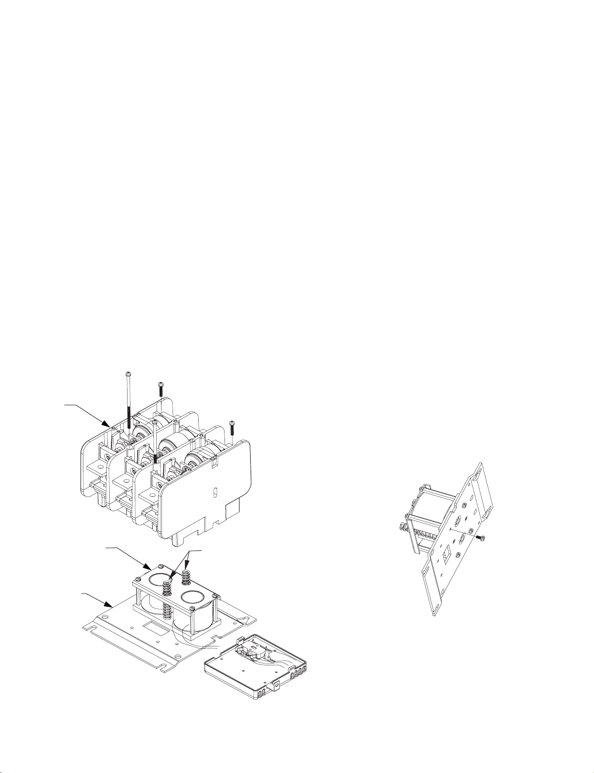
6. While supporting the Main Housing, remove the Main Housing from the Baseplate by removing the (4) screws which
hold the housing to the Baseplate. A long philips-head screwdriver (6 inch or longer) is needed as the four screws are
in deep wells (holes) in the Main Housing. Remove the shorter screws first. Separate the main housing assembly
from the Baseplate and set it aside (Figure 3).
7. Remove the Return Springs and set them aside (Figure 3). Turn the Base Assembly over and remove the (4)
screws that secure the Coil Assembly to the Baseplate (Figure 4).
8. Install new Coil Assembly in position using (4) screws (torque to 30 - 45 lb-inches). Replace the Return Springs by
placing them over the spring support pins located within the coil magnet core assembly making sure the return springs
are properly seated and not interfering with any of the control wiring (Figure 3).
9. Carefully replace the Main Housing assembly loosely, making sure it is orientated correctly. Ensure that no wires
are pinched between housing and baseplate. Carefully locate the magnetic armature poles (the poles sticking down
from the upper housing assembly) into the coil magnet core assembly. Note: This is a blind operation with careful
side to side motion. Pay close attention to alignment of the locating bosses located at the bottom of the main housing
assembly. To reattach the Main Housing assembly insert the main housing locating bosses into the two mounting
plate holes while compressing the return springs with the Main Housing. Start the four Main Housing screws into the
mounting plate. Tighten the mounting screws equally in a diagonal pattern approximately two turns at a time until
torqued to 28 lb-inches in the same diagonal pattern.
Main
Housing
Baseplate
Coil
Assembly
Return
Springs
Figure 3 Figure 4
(2)
Page 3

Coil Replacement (Cont'd)
10. Re-install the Control-Pak or Auxiliary (Figures 5A & 5B). First, rotate the Retainer upwards. Next, insert the
lower tab on the edge of the Control-Pak into the recess on the side of the contactor base. With proper installation,
the Actuator will fit into the hole in the slot in the side of the contactor housing. Using a thin rod or flat blade, lift the
Actuator up as necessary to insert it into the slot mentioned. Rotate the Retainer to its original position, which will
slide over the upper tab on the Control-Pak.
Thin rod or
flat blade
Control-Pak
Actuator
Thin rod or
flat blade
Actuator
must fit
into slot
shown
Figure 5A Figure 5B
Auxiliary
Control-Pak
11. Confirm position of (2) retainers (adjust if necessary) (See Figure 1).
12. Reinstall the cover and secure it with the original mounting hardware. NOTE: Cover must fit under metal
bracket on Control-Pak. Tighten the four screws in a diagonal pattern to 12 lb-in. (Figure 1).
13. Reattach the coil wire leads and any auxiliary control wires to the Control-Pak (tighten to 7 lb-inches).
14. Reinstall the contactor. Torque mounting screws to 50 - 75 lb-inches.
15. Reconnect the line and load conductors and tighten the main terminal hardware and bolts to 180 - 210 lb-inches
(3)
Page 4

42052-091-01 (1)
Printed in U.S.A.
 Loading...