

Page 1
Bulletin 1102C Vacuum Contactor Maintenance and
Installation Instructions (Current Ratings 200A -- 200V-1500V)
(Cat 1102-BO_93 -- 200A, 3 Pole Contactor - 1500V Max)
ATTENTION: To prevent electrical shock, disconnect from power source before installing or servicing.
Inspection page 1
Installation page 2
Coil Replacement page 2, 3
Control Pak Replacement page 4
Aux. Contact Assembly Installation page 4
Vacuum Interrupter Phase Assembly Replacement page 4, 5
Contact Life Over-Travel Measurement page 5
Cleaning and Maintenance page 6
Vacuum Interrupter Integrity Test page 6
Wiring page 6
Dimensions page 7
Replacement Parts page 8
VA
CUUM
CON
TACTO
R
Vacuum Contactor - 200A
Inspection - Unpacking
Before the contactor is placed in service, check carefully for shipping damage. Any damage should be reported to the carrier within (3)
three days of receipt. For overseas deliveries, it is important to obtain a certificate of examination from the nearest insurance inspector and
photographs of the damage. This and other evidence should accompany any communication to the insurance company or shippers. In the
event equipment is to be returned to the factory, contact Allen-Bradley Customer Service Department or our local A-B Distributor for return
authorization. A returned material authorization (RMA) number will be issued which should appear on all correspondence and the returned
container.
The Bulletin 1102C Vacuum Contactor is shipped in a shock resistant filled cardboard box. The following steps should be taken when
unpacking the contactor:
1. Check the packing list against the order to make sure the shipment is complete and components are received.
2. Examine the shipping box before unpacking the contactor to make sure it has not been damaged in shipment. If the shipping box is
damaged, pay particular attention when unpacking to see if the contents are also damaged. Notify the carrier if damage is found and notify
your local Allen-Bradley order field sales office of damage.
Page 2
Installation Instructions
The vacuum contactor may be used in any mounting plane. In any non-horizontal mounting plane, the top of the contactor should point up
(so that the label appears right-side up). Care should be taken to insure that the mounting hardware does not warp the mechanism frame. If
the surface of the contactor to which the contactor is mounted is twisted, shims should be used to correct the condition. Any appreciable
degree of end to end twist will result in phase to phase discrepancies and timing of the main contact could cause increased pickup in control
voltage values.
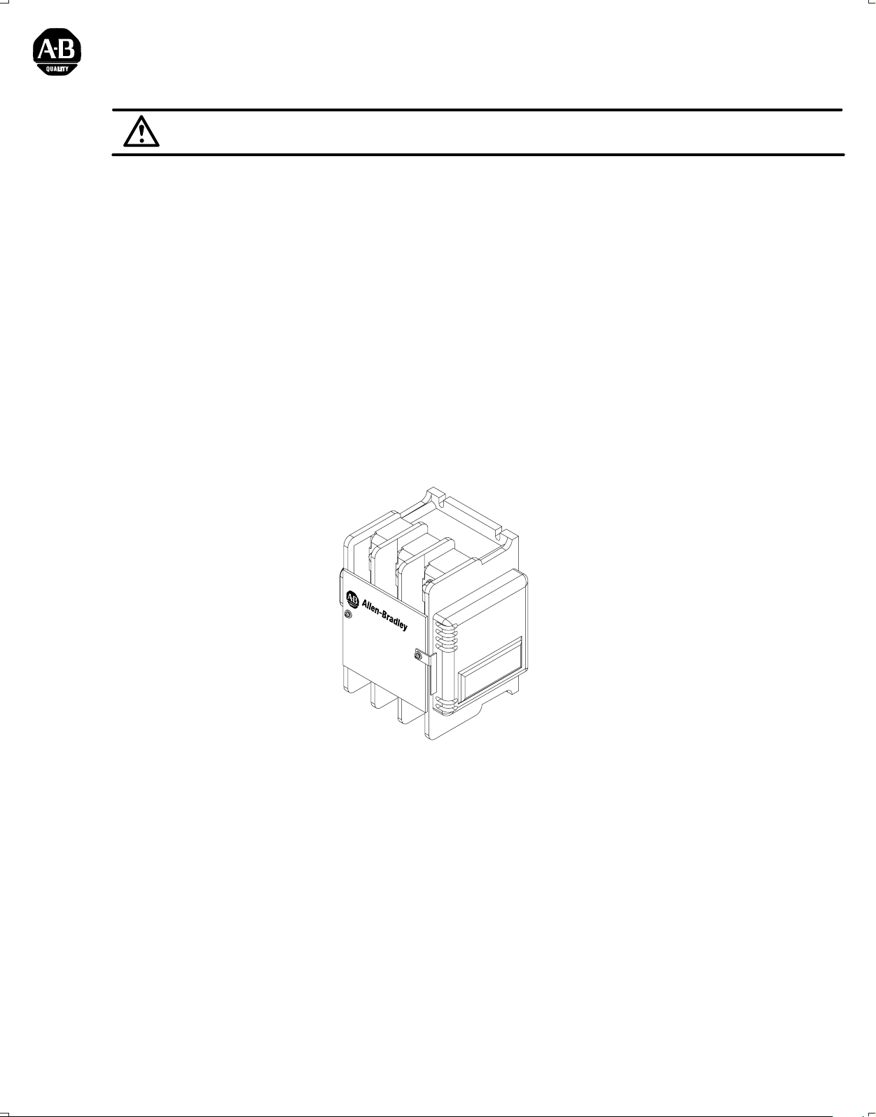
1. Figure 1 illustrates the field terminals for line and load terminations. Mount the contactor with the hardware specified in Figure 2. Loosely
install the (4) mounting bolts into the intended mounting surface. Torque the mounting bolts to 50-75 lb-inches.
2. Connect control wires to the vacuum contactor control terminals A1 and A2 located on the Control-Pak using #18 to #12 gauge 75°C
stranded copper or tin stranded copper wire tightening screw terminals to 7 lb-inches torque.
3. Using 75°C wire copper cable, connect the line and load conductors to the main terminals (Figure 1) and proper phase rotation, tighten the
main terminal bolts to 132 lb-inches torque.
4. Check all connections for accuracy and mechanical connection before energizing.
Line Terminals
Control Pak
1/4 Lock Washer
1/4 Flat
Washer
VACUUM CONTACTOR
A1
Coil
V
A
CU
U
M
C
O
N
T
A
C
T
O
R
Terminals
A2
1/4" or 7mm Bolt
Load Terminals
Figure 1 Figure 2
ATTENTION: If coil failure is suspected, check that secondary damage has not occurred that will render the contactor non-repairable.
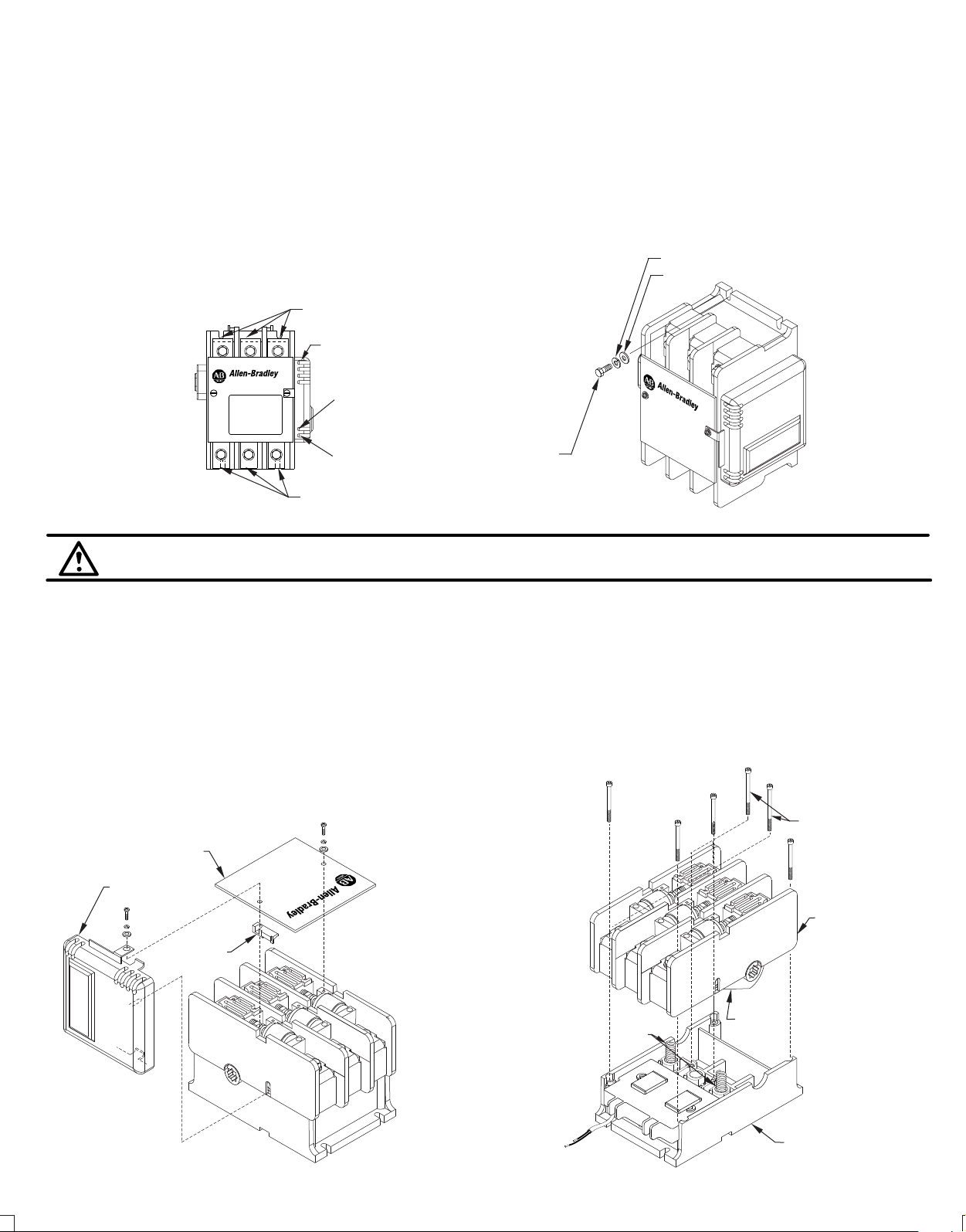
Coil Replacement Instructions
1. Disconnect all power cables (or bus work) and all control wiring to the contactor.
2. Remove the contactor from its mounted location. The contactor is best serviced in the benchtop position as shown.
3. Remove the cover attachment screws from the contactor and remove the Cover and Retainer (Figure 3A).
4. Disconnect the two wire leads from the Coil to the Control-Pak. Remove the Control-Pak from the contactor and set on benchtop (Figure 3B).
5. Remove the (6) screws that secure the Upper Housing to the Lower Housing by first removing the (4) outer screws and then (2) center
screws. NOTE- Removing the center screws will release the Return Springs. Carefully remove the Upper Housing leaving the Return Springs
in the Lower Housing (Figure 3B)).
Center
Screws
Cover
Control-Pak
V
A
C
U
U
M CO
N
T
A
C
T
O
R
Retainer
Return
Springs
Figure 3A Figure 3B
(2)
Upper
Housing
Contact
Operator
Lower
Housing
Page 3
Coil Replacement Instructions (Cont'd)
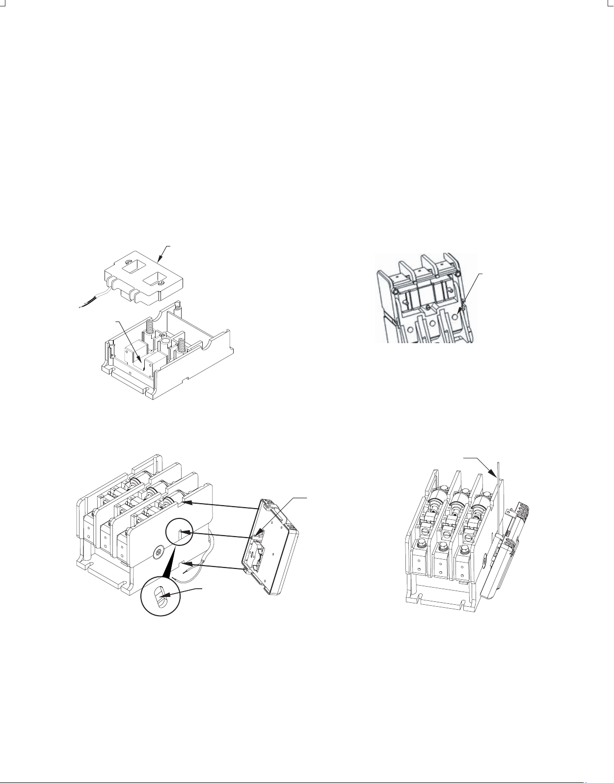
6. Remove and replace the coil. Ensure that the Shim Plate remains in the proper position between the magnet core and coil (Figure 3C).
7. Carefully replace the Upper Housing, ensuring that it is orientated correctly and that the Return Springs are seated on the outer two
bumps on the bottom of the Contact Operator (Figure 3D). Replace the (6) screws that secure the Upper Housing. Tighten the screws
equally in a diagonal pattern approximately two turns at a time until tightened to 12 lb-inches in the same diagonal pattern (Figure 3A).
8. Reinstall the Control-Pak (Figures 3E & 3F). First, insert the lower tab into the recess on the side of the contactor base. With proper
installation, the Control-Pak Actuator will fit into the hole in the slot in the side of the contactor housing. Using a thin rod or flat blade, lift the
Control-Pak Actuator up as necessary to insert it into the slot mentioned
9. Reinstall the cover with Retainer and secure it with the original mounting hardware. Tighten the four screws in a diagonal pattern to 5 lbinches (Figure 3A).
10. Reattach the coil wire leads to the Control-Pak (tighten to 7 lb-inches).
11. Reinstall the device and reconnect any auxiliary control wires. Reconnect the line and load conductors and tighten the main terminal
hardware and bolts to 132 lb-inches.
Coil
Shim
Plate
.
Bumps
Figure 3C
Figure 3D
Thin rod or flat blade
Control-Pak
Actuator
Actuator
must fit into slot
shown
Figure 3E Figure 3F
(3)
Page 4

Control-Pak Replacement Instructions
1. Disconnect all control wiring to the Control-Pak.
2. Remove the cover attachment screws from the contactor and remove the cover (Figure 3A) page 2.
3. Remove the Control-Pak from the contactor (Figure 3A) page 2.
4. Reinstall the Control-Pak (Figures 3E & 3F). First, insert the lower tab into the recess on the side of the contactor base. With proper
installation, the Control-Pak Actuator will fit into the hole in the slot in the side of the contactor housing. Using a thin rod or flat blade, lift
the Control-Pak Actuator up as necessary to insert it into the slot mentioned
5. Reinstall the cover and secure it with the original mounting hardware. Tighten the four screws in a diagonal pattern to 5 lb-inches.
(Figure 3A).
6. Reconnect all control wiring removed per Step 1. Tighten to 7 - 9 lb-inches.
.
(Auxiliary Contact Assembly) Installation Instructions
(Cat 1195C-N3 -- 2-N.O./2-N.C. - 600V @ 10A-A600)
(Cat 1195C-N4 -- 2-N.O./2-N.C. - 5V @ 10mA, DC)
(Positioned left hand side of contactor when facing front)
1. If replacing the existing 1195C Auxiliary Contact, disconnect all control wires from the auxiliary terminals.
2. Remove the cover attachment screws from the contactor and remove the cover (Figure 3A) page 2.
3. Install the new 1195C Auxiliary Contact (Figures 5 and 6). First, insert the lower tab into the recess on the side of the contactor
base. With proper installation, the 1195C Auxiliary Actuator will fit into the hole in the slot in the side of the contactor housing. Using a
thin rod or flat blade, lift the 1195C Auxiliary Actuator up as necessary to insert it into the slot mentioned
4. Reinstall any Control-Pak previously removed per instructions stated above.
5. Reinstall the cover and secure it with the original mounting hardware. Tighten the four screws in a diagonal pattern to 5 lb-inches.
6. Connect all control wiring. Tighten to 7 - 9 lb-inches.
.
Thin rod or
flat blade
Auxiliary
Actuator
Actuator
must fit into
slot shown
Figure 5 Figure 6
Vacuum Interrupter Phase Assembly Replacement Instructions
1. Disconnect all power cables (or bus work) and all control wiring to the contactor.
2. Remove the contactor from its mounted location. The contactor is best serviced in the tabletop position.
3. Remove the cover attachment screws from the contactor and remove the cover (Figure 3A) page 2.
4. Disconnect the two wire leads from the coil to the Control-Pak. Remove the Control-Pak from the contactor and set on benchtop
(Figure 3B) page 2.
5. Locate the replacement vacuum interrupter phase assembly that needs to be replaced.
6. Remove the hardware that secures the shunt to the load side terminal (Figure 7A). This will free the shunt.
7. For the outer interrupters, remove the Retainer. Then remove the hardware securing the Cam Cover before removing the hardware
securing the Interrupter Phase Assembly. Take care to note the position of the shunt prior to removing the Interrupter Phase Assembly.
(Figure 7B).
(4)
Page 5

Vacuum Interrupter Phase Assembly Replacement Instructions (Cont'd)
8. Place the new Interrupter Phase Assembly into the upper housing. Be sure that the Cams are properly seated around the Contact Operator.
Thread the Shunt through the housing and Contact Operator, following the Shunt path (Figure 7C). Replace the hardware securing the
Interrupter Phase Assembly (Figure 7B). Tighten screws to 60 - 80 lb-inches. The replacement interrupter is factory set for contact gap and
does not require adjustment in the field. Attach the Shunt to the load terminal by placing the Shunt against the terminal with the flat washer
and lock washer between the Shunt and the head of the bolt (Figure 7A) and tighten until the lock washer is fully compressed (or up to 60 lbinches). Replace the Cam Cover and hardware (tighten to 60 - 80 lb-inches). Reinstall the Cover and secure it with the original mounting
hardware. Tighten the four screws in a diagonal pattern to 5 lb- inches (Figure 3A). Reattach the coil wire leads to the Control-Pak (tighten to
7 - 9 lb-inches). Reinstall the device and reconnect any auxiliary control wires. Reconnect the line and load conductors and tighten the main
terminal hardware and bolts to 132 lb-inches.
Shunt
Interrupter
Phase Assembly
Cam
Cover
Shunt Path
Contact
Operator
Cam
Orientation
Figure 7A
Figure 7B Figure 7C
Contact Life Over Travel Measurement
The purpose of this measurement is to determine how much vacuum interrupter electrical life remains on the contact and is performed using a
standard wire gauge in a "go, no go" check.
1. De-energize the contactor and isolate from all power sources. The control source can be maintained if coming from a separate supply or if
taken from a line to line connection by application then an additional control source needs to be connected to terminals A1 and A2. Reenergize the contactor insuring that the main power circuits are open and isolated.
2. Remove Phase Cover as described (Figure 3A) page 2, earlier to access inspection area (Figure 8).
3. When the contactor is closed, a gap occurs, and this gap should accept a standard wire (.010") gauge. If the gauge can be inserted in the
space then sufficient life remains for an additional 100,000 operations. Check all phases.
4. If the .010" wire gauge cannot be inserted into this gap with the contactor energized, then over travel has been exhausted and thus contact
life used up. The contactor should be replaced.
Figure 8
(5)
Page 6

Cleaning and Maintenance
1. The vacuum contactor requires no adjustment. Preventative maintenance is recommended on a routine basis, once every twelve
months, dependent upon the environment that the contactor is exposed to. In general, maintenance consists of keeping the device free of
dirt and dust and ensuring the power and control terminals are tight.
2. Maintenance should verify the mechanical operation of the device for freedom of movement. Clean dirt from the surfaces. Pay
particular attention to molded parts and tracking surfaces. Foreign materials on these surfaces should be removed by vacuum or wiping.
Do not use compressed air to remove foreign materials.
Vacuum Interrupter Integrity Test
ATTENTION: Excercise caution while performing high voltage potential tests.
1. A high potential test will determine the di-electric strength and condition of the vacuum interrupter. A high potential test should be
performed on each vacuum interrupter phase in sequence and should be performed approximately once every twelve months.
2. The vacuum interrupter integrity test should be performed if the contactor has been known to be exposed to fault conditions - either
phase to phase or phase to ground.
3. When doing this check, make visual inspection for physical evidence of stress, distorted, discolored or cracked interrupters.
4. A contact resistance test can be done as defined below or if preferred a high potential test; di-electric test should be performed as
follows.
Contact Resistance
A contact resistance test can be performed using a micro-ohmeter. This test determines the condition of contact surfaces. With the
contactor closed, the resistance across the terminals should be less than 400 micro-ohms. If higher contact resistance values are
measured then a high potential test should be performed, as follows:
ATTENTION: The following test should be performed using a 50/60 Hz test set. Where the voltage is continuously variable up to at least
20 kV. X-radiation at this level is negligible. However, personnel should not be closer than ten feet to the interrupter and the test cables to
avoid high voltage shock hazards. The contactor should be free of dust and other contaminants before conducting this test.
1. Disconnect the line and load conductors from the contactor.
2. Connect the leads of the test set across the interrupter terminals with the contactor in the open position.
3. Slowly raise the voltage to 10 KV and hold for 15 seconds.
4. The leakage current should not exceed 5 MA during the test and any tripping of the test set circuit protector during the test should be
repeated two to three times. If it becomes impossible to reach the 10 KV level, then the interrupter needs to be replaced, and should be
replaced by utilizing an Allen-Bradley replacement phase assembly kit.
Wiring
STOP
OPTIONAL (1195C-N3 OR 1195C-N4)
SCHEMATIC
SEPARATE
AC SOURCE
START
M
(14)(13)
(A1)
M
STOP
(A2)
SCHEMATIC SCHEMATIC
SEPARATE
125V DC SOURCE
START
M
(34)(33)
(B1)
(45)
M
LATE
BREAK
STOP
(B2)
(46)
SEPARATE
250V DC SOURCE
START
M
WIRING DIAGRAM WIRING DIAGRAM WIRING DIAGRAM
L1
(53)
(54)
(61)
(62)
(73)
(74)
(81)
(82)
(53) (13)
(54)
(61)
(62) (22)
(73)
(74)
(81)
(82)
T1
L3L2L1
(14)
(21)
M
T2
(A1)
(A2)
T3
L1 L2 L3
(53) (13)
(54)
(61)
(62)
(73)
CONTROL PAK
(74)
(81)
OPTIONAL (1195C-N3 OR 1195C-N4)
(82)
M
T3T2T1
(B2)
(B1)
(14)
(21)
(22)
(33)
(34)
(45)
LATE
BREAK
(46)
1195C-N5
OPTIONAL (1195C-N3 OR 1195C-N4)
M
(B1)
(34)(33)
L2
L3
M
T2T1
T3
(26)(25) (45)(46)
LATE
BREAK
(13)
(14)
(25)
(26)
(33)
(34)
(45)
LATE
BREAK
(46)
(B2)
(B1)
(B2)
LATE
BREAK
(6)
1195C-N6
Page 7

Dimensions
[17.1 mm]
.9
[22.7 mm]
.68
6.44
[163.5 mm]
5.3
[134.5 mm]
3.5
[89.0 mm]
(4) Mounting for 1/4 Screws
.34
[8.5 mm]
.32
[8.1 mm]
5.93
[150.6 mm]
Optional
Aux. Contact
Kit
[25.1 mm]
1.0
1 L1 3 L2 5 L3
VACUUM CONTACTOR
2 T1 4 T2 6 T3
3.3
[84.3 mm]
13
NO
14
21
NC
22
A600
P300
7.5
[190.6 mm]
NONCFORM X
A600
P300
FORM Y
14 13
22 21
8.66
[219.9 mm]
8.32
[211.3 mm]
A1
COIL
A2
(7)
Page 8

Replacement Parts
Auxiliary Kits
Type - Contact Arrangement
(200 Amp.)
Current Rating W/ Wire Gauge Range
(2) N.O. / N.C. 5 VDC 10mA
(2) N.O. / N.C. 600 VAC 10 Amp. (A600)
Control Pak ---- side mounted module for DC coil power
Bulletin Number Voltage (input) Contactor Size (Amp. Rating)
110/120 VAC1102C-CP2D
1102C-CP2A 220/240 VAC
380/415 VAC1102C-CP2N
1102C-CP2B 440/480 VAC
Coil Kit ---- This kit contains the DC coil mounted in the sheet metal frame assembly
which attaches to the contactor mounting plate.
NOTE: When changing the coil voltage, verify that the Control-Pak voltage for the coil
kits listed below is in agreement with the Control-Pak nameplate input voltage.
Bulletin Number Voltage (input) Control Pak Volts (Amp. Rating)
1102C-PK2D 108 VDC 110/120 VAC
1102C-PK2A 108 VDC 220/240 VAC
1102C-PK2N 108 VDC 380/415 VAC
1102C-PK2B 108 VDC 440/480 VAC
1102C-PK2G 125 VDC NONE
1102C-PK2H
250VDC NONE
1102C-BOD93 (200 Amp.)
1102C-BOA93 (200 Amp.)
1102C-BON93 (200 Amp.)
1102D-BOB93 (200 Amp.)
(200 Amp.)
Accessories
Interrupter Phase Assembly Kit - Replacement for One Vacuum Interrupter Phase
Bulletin Number
1102C-VB2
Bulletin Number
1195C-N3
1195C-N4
1195C-N5
1195C-N6
Lug Kits
Bulletin Number
1195C-LK1
For use on DC input coils only - 125 VDC maximum
For use on DC input coils only - 250 VDC maximum
Current Rating of Interrupter
200 A Vaccum Interrupter Phase Assembly
(1) N.O. / N.C. & (1) N.O. /Late Break N.C.
(2) N.O. / Late Break N.C.
200 A 2/0 - 250 MCM
42052-087-01(1)
Printed in U.S.A.
 Loading...