


 Loading...
T U B E D R I V E N P R O G R A M M A B L |
E |
2 4 - B I T D S P |
G U I T A R P R E A M |
P |
|
USER'S MANUAL
May be covered by one or more of the following: U.S. Patents #4538297, 4647876, 4696044, 4745309, 4881047, 4893099, 5124657, 5263091, 5268527, 5319713, 5333201, 5402498, 5493617 and 5638452. Other patents pending. Foreign patents pending.

Your VooDu Valve Online has been tested and complies with the following Standards and Directives as set forth by the European Union:
Council Directive(s): |
89/336/EEC Electromagnetic Compatibility |
Standard(s): |
EN55022, EN50082-1 |
This means that this product has been designed to meet stringent guidelines on how much RF energy it can emit, and that it should be immune from other sources of interference when properly used. Improper use of this equipment could result in increased RF emissions, which may or may not interfere with other electronic products.
To insure against this possibility, always use good shielded cables for all audio input and output connections. This will help insure compliance with the Directive(s).
Copyright © 1997 Rocktron Corporation. All rights reserved.

Contents |
|
1. Introduction ................................................................................................. |
1 |
2. Quick Setup ................................................................................................. |
3 |
3. Front Panel .................................................................................................. |
4 |
4. Rear Panel ................................................................................................... |
6 |
5. Connections ................................................................................................ |
8 |
Using the Voodu Valve™ with a stereo power amp and guitar cabinets ......................... |
8 |
Using the Voodu Valve™ direct into a mixing console ................................................... |
9 |
6. Operating Format ....................................................................................... |
11 |
Voodu Valve Functions and Parameter Descriptions ................................................... |
12 |
GLOBAL Function ........................................................................................................ |
13 |
MIXER Function ........................................................................................................... |
14 |
HIGH GAIN Function .................................................................................................... |
15 |
LOW GAIN Function ..................................................................................................... |
16 |
HUSH® Function .......................................................................................................... |
17 |
PRE EQ (EXPERT) Function ....................................................................................... |
18 |
POST EQ (EXPERT) Function..................................................................................... |
19 |
COMPRESSOR Function ............................................................................................. |
20 |
SPEAKER SIMULATOR Function ............................................................................... |
21 |
WAH-WAH Function ..................................................................................................... |
22 |
PHASER Function........................................................................................................ |
23 |
FLANGER Function ...................................................................................................... |
24 |
TREMOLO Function ..................................................................................................... |
25 |
PITCH SHIFT Function ................................................................................................ |
26 |
CHORUS Function ....................................................................................................... |
28 |
DELAY Function ........................................................................................................... |
30 |
REVERB Function........................................................................................................ |
32 |
7. Voodu Valve™ Configurations ................................................................. |
33 |
H-GAIN, CRS, DLY, REV Configuration ....................................................................... |
33 |
H-GAIN, FLAN, DLY, REV Configuration ..................................................................... |
36 |
H-GAIN, TREM, DLY, REV Configuration .................................................................... |
39 |
H-GAIN, PSHF, DLY, REV Configuration ..................................................................... |
42 |
WAH, H-GAIN, DLY, REV Configuration ...................................................................... |
45 |
PHAS, H-GAIN, DLY, REV Configuration .................................................................... |
48 |
L-GAIN, CRS, DLY, REV Configuration ....................................................................... |
51 |
L-GAIN, FLAN, DLY, REV Configuration ...................................................................... |
54 |
L-GAIN, TREM, DLY, REV Configuration ..................................................................... |
57 |
L-GAIN, PSHF, DLY, REV Configuration ..................................................................... |
60 |
WAH, L-GAIN, DLY, REV Configuration ....................................................................... |
63 |
PHASE, L-GAIN, DLY, REV Configuration................................................................... |
66 |
8. Operating the Voodu Valve™ ................................................................... |
69 |
Selecting a preset ........................................................................................................ |
69 |
Changing preset parameters ......................................................................................... |
70 |
Storing changed preset parameters .............................................................................. |
71 |
Selecting a configuration .............................................................................................. |
73 |
Editing a preset title ..................................................................................................... |
75 |
Controller Assignments ................................................................................................ |
77 |
Tap Delay ..................................................................................................................... |
80 |
Program Changes ......................................................................................................... |
83 |
MIDI Channels .............................................................................................................. |
85 |
MIDI Dump/Load .......................................................................................................... |
87 |
Factory Restore ............................................................................................................ |
93 |
Restoring a single factory preset: ..................................................................................... |
93 |
Restoring a single factory preset: ..................................................................................... |
95 |
Restoring the Voodu Valve controller assignments: ........................................................ |
96 |
Selecting a Power On Preset ....................................................................................... |
97 |
Using the Voodu Valve with a Rocktron All Access™ in REMOTE mode ................... |
98 |
9. Appendix .................................................................................................. |
101 |
ERROR MESSAGES ................................................................................................. |
101 |
MIDI IMPLEMENTATION .......................................................................................... |
102 |
TECHNICAL DATA ..................................................................................................... |
103 |

1. Introduction
Congratulations on your purchase of the RocktronVoodu Valve™ Online !
The Voodu Valve Online features presets created and uploaded by Rocktron users from all over the world to Rocktron's World Wide Web site. These presets can be easily updated from the "Patch Bay" at Rocktron's web page. In addition, you can also upload your own custom presets to share with other online users. For instructions on downloading and uploading Voodu Valve presets, please visit our web site at "http://www.rocktron.com" and click "Patch Bay".
The Voodu Valve™ Online is a 24 bit DSP professional tube guitar preamp providing 12 unparalleled effect algorithms and superb sound quality never before heard from a digital tube guitar preamp. Complete programmability and full MIDI implementation are coupled with a user friendly operating format to ensure that designing unique and useful preset sounds is as simple as possible.
In addition, the Voodu Valve™ Online also features:
•Advanced Speaker Simulation provides a strikingly realistic approximation of a miked speaker cabinet at line-level for direct mixer input or headphone listening.
•Full parametric Pre and Post EQ gives the user complete EQ control over each preset.
•HUSH® Noise Reduction provides noise reduction while playing and complete silence when not.
•"Variac" Simulation, like a conventional Variac, adjusts the level at which the preamp begins to distort. This provides more gain in high-gain applications, and allows for full-bodied cleaner presets which just begin to distort when the strings are attacked harder.
•Internal Wah-Wah allows the player to use an expression pedal for Wah-Wah effects instead of running long audio cables out to a conventional Wah-Wah pedal.
•High-quality Digital Effects, including:
-Reverb |
-Phasing |
-Tremolo |
-Flanging |
-Pitch Shifting |
-Compression |
-Chorus |
-Delay |
• XLR Outputs for direct mixer input.
This manual will detail the various features and functions of the Voodu Valve Online. After reading it, please keep it for future reference.
1

OPERATING PRECAUTIONS
NOTE: IT IS VERY IMPORTANT THAT YOU READ THIS SECTION TO PROVIDE YEARS OF TROUBLE FREE USE. THIS UNIT REQUIRES CAREFUL HANDLING.
All warnings on this equipment and in the operating instructions should be adhered to and all operating instructions should be followed.
Do not use this equipment near water. Care should be taken so that objects do not fall and liquids are not spilled into the unit through any openings.
The power cord should be unplugged from the outlet when left unused for a long period of time.
DO NOT ATTEMPT TO SERVICE THIS EQUIPMENT. THIS EQUIPMENT SHOULD BE SERVICED BY QUALIFIED PERSONNEL ONLY. DO NOT MAKE ANY INTERNAL ADJUSTMENTS OR ADDITIONS TO THIS EQUIPMENT AT ANY TIME. DO NOT TAMPER WITH INTERNAL ELECTRONIC COMPONENTS AT ANY TIME. FAILURE TO FOLLOW THESE INSTRUCTIONS MAY VOID THE WARRANTY OF THIS EQUIPMENT, AS WELL AS CAUSING SHOCK HAZARD.
POWER REQUIREMENTS
This unit accepts power from the 9VAC/3.4A adaptor supplied with the unit. This 9 volt RMS AC voltage is internally processed by a voltage doubler which generates a bipolar ±15 volts to maintain the headroom and sound quality of professional, studio quality equipment. Using an external power source such as this minimizes excessive noise and hum problems often associated with internal transformers, providing optimal performance for the user.
OPERATING TEMPERATURE
Do not expose this unit to excessive heat. This unit is designed to operate between 32° F and 104° F (0° C and 40° C). This unit may not function properly under extreme temperatures.
2
2. Quick Setup
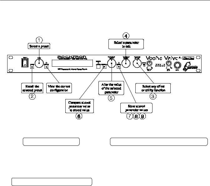
SELECTING A PRESET
STEP 1 Turn the PRESET control to the desired preset.
STEP 2 Press the RECALL button to call up the selected preset.
CHANGING PRESET PARAMETERS
STEP 3 Turn the FUNCTION SELECT control to the desired effect or utility function.
STEP 4 Turn the PARAMETER SELECT control to the parameter you wish to alter under the selected effect or utility function.
STEP 5 Use the PARAMETER ADJUST control to select the new parameter value.
STEP 6 The COMPARE button may be used to compare the sound of the altered value to the stored value.
STORING CHANGED PARAMETERS
STEP 7 Press the STORE button to start the storing procedure.
STEP 8 If you wish to save the altered preset in the current preset location, press the STORE button a second time.
If you wish to store the altered preset in a different preset location, turn the PRESET control to the desired preset number, then press STORE a second time.
STEP 9 When storing into a different preset location, the Voodu Valve will display "COPY TITLE
TOO?". If you wish to copy the title from the previous preset, press STORE a third time. If you do not wish to copy the title, turn any knob to exit the storing procedure.
3

3. Front Panel
1POWER switch
2RECALL button
This button is used to recall the displayed preset.
3 |
PRESET control |
|
This control scrolls through the successive presets. |
4 |
CONFIG button/led |
|
The status of this button determines whether the Voodu Valve™ will display |
|
either the preset number and title or the configuration of the currently displayed |
|
preset. The configuration display indicates the effects that the displayed preset |
|
executes and, in most cases, the order in which they are executed. |
|
The LED above the CONFIG button is lit when the configuration is displayed. |
5 |
DISPLAY panel |
|
The DISPLAY panel provides 16 characters consisting of 14 segments each. |
6 |
EFFECT BYPASS button/led |
|
When lit, the Pre and Post effects are bypassed and only the Compressor/Preamp |
|
signal is passed to the Voodu Valve™ outputs. This button does not affect the |
|
condition of the Speaker Simulator. |
7 |
COMPARE button |
|
The COMPARE button may be used to compare an altered parameter value to its |
|
stored value. |
This button may also be used to compare between the altered and stored values of multiple parameters under the same function heading (i.e. "Reverb", "Mixer", etc.).
Note: If comparing an altered value to the stored value and the stored value is currently being viewed, turning a knob or pressing a button that changes the parameter value displayed will cancel the previous altered value. This will also occur if a MIDI control change is received while viewing the stored value(s).
4

8 PARAMETER ADJUST control
This control is used to adjust a displayed parameter value. When the parameter is changed from its original value, the LED above the STORE button will light until either the new value is stored, a new preset is selected or the parameter is returned to its original value.
9 STORE button/led
This button is used to store values into the Voodu Valve™ memory when altered.
See "Storing Changed Preset Parameters" in Chapter 8 for more information on this procedure.
10 PARAMETER SELECT control
When adjusting parameter values, this control will scroll through the available parameters under the current function heading.
In the "Title Edit" function, this control will scroll through the character locations to be edited.
11 FUNCTION SELECT control
This control allows access to each function of the Voodu Valve™. Depending on what configuration is currently recalled, these functions include:
Global |
Pre EQ (Expert) |
Phaser |
Delay |
Footswitch |
Mixer |
Post EQ (Expert) |
Flanger |
Reverb |
Program Changes |
High Gain |
Compressor |
Tremolo |
Config Select |
MIDI Channels |
Low Gain |
Speaker Simulator Pitch Shift |
Title Edit |
MIDI Dump/Load |
|
HUSH |
Wah-Wah |
Chorus |
Controller Assig |
Factory Restore |
12 SPEAKER SIMULATOR indicator
When lit, this LED indicates that the Speaker Simulator is activated for the current preset.
13 OUTPUT LEVEL control
This control is used to adjust the output level of the unit at the unbalanced outputs.
14 INPUT LEVEL meter
These LEDs provide visual indication of the peak level of the input signal when in the Preset Select mode. For the optimal signal-to-noise ratio, it is best to adjust the input level so that the last LED (0dB) is rarely lit. This will guard against the possibility of overdriving the unit.
These LEDs also display the final digital mixer output levels when any other functions are selected. This will help you to guard against clipping the output of the mixer at the digital-to-analog converter.
15 INPUT LEVEL control
This control adjusts the unit’s gain to match the signal level at the input of the Voodu Valve™. Use the INPUT LEVEL meter to determine the setting of this control.
16 INPUT jack
This standard, unbalanced mono 1/4" jack is used to provide input to the unit. It is front panel mounted for easy access.
5
4. Rear Panel
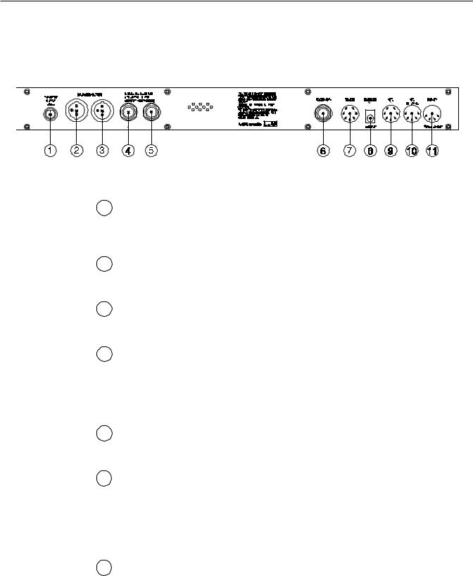
1 BALANCED OUTPUT LEVEL control
This control determines the output level at the XLR BALANCED OUTPUTS. Note that the balanced outputs pass the same signals as the unbalanced outputs, except that the levels are independently adjustable.
2 (L) BALANCED OUTPUT connector
This balanced XLR connector provides the left balanced output of the Voodu Valve for direct use into a mixing console.
3 (R) BALANCED OUTPUT connector
This balanced XLR connector provides the right balanced output of the Voodu Valve for direct use into a mixing console.
4 (L) UNBALANCED OUTPUT jack
This 1/4" unbalanced RTS jack provides the left unbalanced output of the Voodu Valve for use with a guitar amplifier or rack system setup.
In addition, this jack also allows for the connection of stereo headphones (600Ω impedance or greater).
5 (R) UNBALANCED OUTPUT jack
This 1/4" unbalanced RTS jack provides the right unbalanced output of the Voodu Valve for use with a guitar amplifier or rack system setup.
6 FOOTSWITCH jack
This 1/4" mono jack allows for the connection of a momentary footswitch to control the Tapped Delay feature of the Voodu Valve. The Tapped Delay feature allows the player to set (or reset) the current delay time by tapping the footswitch. The new delay time will be based on the length of time between two taps. For more information on this feature, refer to the "Tap Delay" section in Chapter 8.
7 REMOTE jack
This 7-pin DIN connector is provided for the connection of a Rocktron All Access™ MIDI footswitch, which can be configured to act as a dedicated remote footswitch for the Voodu Valve. This feature allows the user to access Voodu Valve functions and parameters via the remote footswitch.
6

8 PHANTOM POWER jack
This 2.5mm PIN jack offers the ability to power Rocktron MIDI foot controllers from a 7-pin MIDI cable which connects from the Rocktron MIDI foot controller to the MIDI IN jack on the rear panel of the Voodu Valve. This eliminates the need to find an AC outlet near where the footpedal would be placed during a performance, or the need to run an extension cord out to the footswitch. Instead of inserting the AC adaptor into the "POWER" jack of the footswitch as you would normally, plug it into the "PHANTOM POWER" jack on the Voodu Valve. This will power the Rocktron MIDI foot controller through pins 6 and 7 of the MIDI cable connecting the two units. A 7-pin MIDI cable must be used and is available from your Rocktron dealer.
9 MIDI IN jack
This 7-pin DIN connector must be connected to the MIDI OUT jack of the transmitting MIDI device via a standard MIDI cable, or to the MIDI THRU jack of the preceding device (if the Voodu Valve is within a chain of MIDI devices).
Pins 6 and 7 of this connector carry the phantom power to power a Rocktron MIDI foot controller when a 7-pin MIDI cable is used.
10 MIDI THRU/OUT jack
This standard 5-pin DIN connector can be connected to the MIDI IN jack of another device via a standard MIDI cable. There are limitations to the number of devices that can be chained (or series connected) in this fashion.
Note: Inherently in MIDI there is a limit to the number of devices which can be chained together (connected in series). With more than 3 devices, a slight distortion of the MIDI signal can occur (due to signal degradation) which can cause an error in MIDI signal transmission. Should this problem arise, a MIDI Thru box can be used which connects directly to the MIDI device which transmits MIDI information and has multiple connectors for the multiple devices receiving MIDI. MIDI cables should not exceed 50 feet (15 meters) in length.
11 POWER jack
This 4-pin DIN connector accepts power from the 9VAC adaptor supplied with the unit.
7

5. Connections
Using the Voodu Valve™ with a stereo power amp and guitar cabinets
8
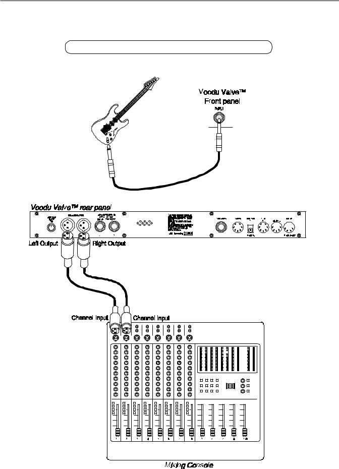
Using the Voodu Valve™ direct into a mixing console
9

6. Operating Format
The Voodu Valve provides 254 stored sounds called presets. Any of the 254 presets can be called up at any time via the front panel PRESET control (used to select a preset) and RECALL button (used to call up the selected preset), or by a remote MIDI footswitch.
The root of each preset’s sound is itsconfiguration. The configuration determines both the effects available for a given preset and the order in which those effects are executed. The Voodu Valve provides 12 fixed configurations to achieve a wide array of preset sounds, any of which may be instantly called up at any time.
Voodu Valve™ Configurations:
•High-gain Distortion - Chorus - Delay - Reverb
•High-gain Distortion - Flange - Delay - Reverb
•High-gain Distortion - Tremolo - Delay - Reverb
•High-gain Distortion - Pitch Shift - Delay - Reverb
•Wah - High-gain Distortion - Delay - Reverb
•Phase Shift - High-gain Distortion - Delay - Reverb
•Low-gain Distortion - Chorus - Delay - Reverb
•Low-gain Distortion - Flange - Delay - Reverb
•Low-gain Distortion - Tremolo - Delay - Reverb
•Low-gain Distortion - Pitch Shift - Delay - Reverb
•Wah - Low-gain Distortion - Chorus - Delay - Reverb
•Phase Shift - Low-gain Distortion - Delay - Reverb
To see the configuration of each preset, press the CONFIG button on the front panel of the Voodu Valve—the LED above the CONFIG button will light and the display will show the configuration for the current preset. Turning the PRESET control will then scroll through each successive preset (displaying its configuration instead of its preset number and title).
The configuration of each preset can also be changed from within the desired preset. For more information on selecting a configuration, see “Selecting a Configuration” in Section 8, "Operating the Voodu Valve".
11

Voodu Valve Functions and Parameter Descriptions
Each Voodu Valve preset is divided up into individual blocks calledfunctions (such as "Mixer", "Reverb", etc.). Within each function of each configuration is a set of controls which allow you to manipulate various aspects of that function. These controls are called parameters. It is the setting of each of the parameters which determines the overall sound of each preset.
The Voodu Valve is set up to allow you to first access each function (via the FUNCTION SELECT control), then the parameter list for each function (via the PARAMETER SELECT control) and finally the adjustable value for each parameter (via the PARAMETER ADJUST control).
Step 3:
Turn to alter the value of the selected parameter.
Step 2: |
Step 1: |
Turn to select a parameter within Turn to select a function. the selected function.
The functions available for each preset are dependent upon which configuration is currently recalled. The remainder of this section will describe each of the effect-based functions and the associated adjustable parameters they provide.
The remaining functions are utility-based, and are described in Section 8, "Operating the Voodu Valve".
12

GLOBAL Function
The first function displayed after turning the FUNCTION SELECT control is the Global function. The parameters provided in this function affect all presets (i.e. the settings stored for these parameters are the same for all presets).
The PARAMETER SELECT control will allow you to access these Global parameters:
OUTPUT |
The OUTPUT parameter determines whether the output of the Voodu |
|
Valve is a stereo (left and right) signal or two mono signals. |
SPKR SIM |
This SPEAKER SIMULATOR parameter under the Global function |
|
allows you to globally (all presets) lock the Speaker Simulator off |
|
(LOCKOFF) so that it will always be off for all presets - regardless of |
|
the status of the “SPKR SIM” parameter under the Speaker Simulator |
|
function. It may also be locked on for the left channel (LOCK L) or on |
|
for both channels (LOCK B). |
|
Note: The Voodu Valve will only recognize the “SPKR SIM” parameter |
|
under the Speaker Simulator function when this parameter is stored as |
|
UNLOCK. |
HUSH OFFSET |
The HUSH OFFSET parameter allows you to globally (all presets) |
|
adjust the HUSH® Expander Threshold. This means that if this param- |
|
eter is altered from 0dB to +3dB, the Expander Threshold will be 3dB |
|
higher for all presets. This feature can be useful when switching from a |
|
quiet guitar with passive electronics to a noisy guitar with active |
|
electronics - as the active guitar would require a higher Threshold level |
|
in all presets. |
MUTE |
The MUTE parameter allows you to mute the output of the Voodu Valve. |
|
This feature is especially useful when changing guitars during a live set. |
|
If a Rocktron All Access™ is used in remote mode with the Voodu |
|
Valve, a single All Access button can be configured as a momentary |
|
switch which will mute the output when it is held down. (See "Using a |
|
Voodu Valve with a Rocktron All Access in REMOTE mode" in Chapter |
|
8 for more information.) |
13

MIXER Function
The next function displayed after turning the FUNCTION SELECT control is the Mixer function. The Mixer function parameters are included in all presets—regardless of which configuration is currently recalled—although the parameter values stored in this function are only for the currently recalled preset.
This digital mixer allows you to control most signal levels pertaining to each preset’s configuration and stores these levels for each preset.
The PARAMETER SELECT control will allow you to access these Mixer parameters:
VOLUME |
The VOLUME parameter determines the overall signal level of the |
|
current preset. |
LEFT OUT LVL |
The LEFT OUT LEVEL parameter allows you alter the level of the left |
|
channel output of the current preset independent of the right channel. |
RIGHT OUT LVL |
The RIGHT OUT LEVEL parameter allows you alter the level of the |
|
right channel output of the current preset independent of the left |
|
channel. |
MIX DIR/EFF |
The DIR/EFF MIX parameter is used to define the ratio of direct signal |
|
level to effect (Chorus, Flange, Pitch Shift) signal level. |
DIR PAN |
The DIRECT PAN parameter allows you to pan the direct signal to the |
|
left or right. |
DELAY LVL |
The DELAY LEVEL parameter determines the overall level of the |
|
delayed signal at the output relative to the direct signal and other effect |
|
signals. This parameter can also be accessed from the Delay function |
|
parameter list. |
REVERB LVL |
The REVERB LEVEL parameter determines the level of the reverb |
|
signal at the output relative to the direct signal and other effect signals. |
|
This parameter can also be accessed from the Reverb function param- |
|
eter list. |
14

HIGH GAIN Function
The HIGH GAIN function is only accessible in configurations which display "H-GAIN" in the configuration title. The preamp stage in these configurations is set up to provide high gain levels for maximum sustain and distortion.
The PARAMETER SELECT control will allow you to access these High Gain parameters:
TUBE GAIN |
The TUBE GAIN parameter sets the amount of drive at the input of the |
|
tube stage. |
GAIN |
The GAIN parameter determines the gain value in the distortion stage. |
VARIAC ADJUST |
The VARIAC ADJUST parameter adjusts the level at which the preamp |
|
stage in the Voodu Valve begins to distort. A Variac is a voltage- |
|
attenuating device that plugs into an AC wall outlet and adjusts the |
|
voltage level to any device which is plugged into it. For years, many |
|
guitarists have plugged their amplifier heads into a Variac and reduced |
|
the voltage coming into the amplifier from the AC wall outlet. This |
|
allows the amplifier tubes to reach saturation at a lower input level and |
|
increases the gain produced. The VARIAC ADJUST parameter |
|
operates in a similar manner as a conventional Variac - where lowering |
|
the parameter value lowers the level at which saturation will take place. |
BASS LVL |
The post BASS LEVEL parameter adjusts the amount of low frequency |
|
information at the output of each preset. This parameter is also acces- |
|
sible from the "Post EQ (Expert)" function. (In the Post EQ function, |
|
the center frequency and bandwidth of this EQ section are also adjust- |
|
able.) |
MID LVL |
The post MID LEVEL parameter adjusts the amount of mid frequency |
|
information at the output of each preset. This parameter is also acces- |
|
sible from the "Post EQ (Expert)" function. (In the Post EQ function, |
|
the center frequency and bandwidth of this EQ section are also adjust- |
|
able.) |
TREBLE LVL |
The post TREBLE LEVEL parameter adjusts the amount of high |
|
frequency information at the output of each preset. This parameter is |
|
also accessible from the "Post EQ (Expert)" function. (In the Post EQ |
|
function, the center frequency and bandwidth of this EQ section are also |
|
adjustable.) |
PRESENCE LVL |
The post PRESENCE LEVEL parameter also adjusts the amount of |
|
high frequency information at the output of each preset. This parameter |
|
is also accessible from the "Post EQ (Expert)" function. (In the Post EQ |
|
function, the center frequency and bandwidth of this EQ section are also |
|
adjustable.) |
15

LOW GAIN Function
The LOW GAIN function is only accessible in configurations which display "L-GAIN" in the configuration title. The preamp stage in these configurations provides four distortion types, and can also be used for clean tones.
The PARAMETER SELECT control will allow you to access these Low Gain parameters:
TUBE GAIN |
The TUBE GAIN parameter sets the amount of drive at the input of the |
|
tube stage. |
GAIN |
The GAIN parameter determines the gain value in the distortion stage. |
TUBE |
The TUBE parameter allows you to select between four different tube |
|
distortion types - Hard Clip, Soft Clip, Class A, Class B. The Hard Clip |
|
setting provides the hardest clipping, while the Soft Clip type provides a |
|
softer clipping and the Class A and B types provide the softest clipping. |
|
The Class A setting produces non-symmetrical clipping - therefore |
|
more even harmonics are produced. Conversely, the Class B setting |
|
produces symmetrical clipping. The differences between these types |
|
are most pronounced at moderate gain settings of about 30dB or less, |
|
where Class B produces the least amount of upper harmonics. |
BASS LVL |
The post BASS LEVEL parameter adjusts the amount of low frequency |
|
information at the output of each preset. This parameter is also acces- |
|
sible from the "Post EQ (Expert)" function. (In the Post EQ function, |
|
the center frequency and bandwidth of this EQ section are also adjust- |
|
able.) |
MID LVL |
The post MID LEVEL parameter adjusts the amount of mid frequency |
|
information at the output of each preset. This parameter is also acces- |
|
sible from the "Post EQ (Expert)" function. (In the Post EQ function, |
|
the center frequency and bandwidth of this EQ section are also adjust- |
|
able.) |
TREBLE LVL |
The post TREBLE LEVEL parameter adjusts the amount of high |
|
frequency information at the output of each preset. This parameter is |
|
also accessible from the "Post EQ (Expert)" function. (In the Post EQ |
|
function, the center frequency and bandwidth of this EQ section are also |
|
adjustable.) |
PRESENCE LVL |
The POST PRESENCE LEVEL parameter also adjusts the amount of |
|
high frequency information at the output of each preset. This parameter |
|
is also accessible from the "Post EQ (Expert)" function. (In the Post EQ |
|
function, the center frequency and bandwidth of this EQ section are also |
|
adjustable.) |
16

HUSH® Function
The HUSH®function is accessible in all presets—regardless of the configuration currently recalled.
HUSH is Hush Systems’ patented single-ended noise reduction system. The HUSH system contained in the Voodu Valve, though modeled after the latest analog HUSH design, is a fully digital implementation achieved through Digital Signal Processing (DSP).
The low level expander of the HUSH system operates like an electronic volume control. The analog version of the HUSH utilizes a voltage-controlled amplifier (VCA) circuit which can control the gain between the input and the output from unity to 30, 40 or even 50dB of gain reduction. When the input signal is above the user preset threshold point, the VCA circuit remains at unity gain. (This means that the amplitude of the output signal will be equal to that of the input signal.) As the input signal level drops below the user preset threshold point, downward expansion begins. At this point the expander acts like an electronic volume control and gradually begins to decrease the output signal level relative to the input signal level. As the input signal drops further below the threshold point, downward expansion increases. A drop in the input level by 20dB would cause the output level to drop approximately 40dB (i.e., 20dB of gain reduction). In the absence of any input signal, the expander will reduce the gain so that the noise floor becomes inaudible.
The HUSH circuit is located after the A/D converter in the signal chain to reduce any noise generated from the guitar and the A/D converter. This ensures a quiet input signal to the preamp section. Because the preamp section of the Voodu Valve™ is digital, it is virtually noise-free (even in the high-gain mode). Therefore, a quiet input signal to the preamp will result in a quiet output signal.
The PARAMETER SELECT control will allow you to access these Hush® parameters:
HUSH I/O |
The HUSH I/O parameter simply determines whether the HUSH® |
|
circuit is active for the current preset. |
HUSH THRESH |
The HUSH THRESHOLD parameter determines the level at which |
|
downward expansion begins. For example, if the HUSH THRESHOLD |
|
was set at -20dB and the input signal dropped below -20dB, downward |
|
expansion would begin. |
17

PRE EQ (EXPERT) Function
The PRE EQ (EXPERT) function is available in all presets—regardless of which configuration is currently recalled.
This function allows you to shape the tone prior to the distortion stage. Considerable tone variations can be achieved by modifying these pre-distort EQ parameters.
The PARAMETER SELECTcontrol will allow you to access these PRE EQ parameters:
LF LEVEL |
The pre-LF (low frequency) LEVEL parameter allows you to cut or |
|
boost the low frequencies from -15dB to +6dB prior to the distortion |
|
stage. This EQ section is a shelving-type. |
LF FREQ |
The pre-LF (low frequency) FREQUENCY parameter allows you to |
|
select a frequency band with an upper frequency between 63Hz and |
|
500Hz to be cut or boosted by the pre-LF LEVEL parameter. |
MID LEVEL |
The pre-MID LEVEL parameter allows you to cut or boost the mid- |
|
band frequencies from -15dB to +12dB prior to the distortion stage. |
MID FREQ |
The pre-MID FREQUENCY parameter allows you to select a mid-band |
|
center frequency between 500Hz and 4KHz to be cut or boosted via the |
|
pre-MID LEVEL parameter. |
MID BW |
The pre-MID BANDWIDTH parameter determines how wide or |
|
narrow the bandwith of the selected mid-band frequency is (in octaves). |
|
A small bandwidth only boosts or cuts frequencies close to the center |
|
frequency, while a large bandwidth affects the level of frequencies up to |
|
two octaves from the center frequency. |
18
POST EQ (EXPERT) Function
The POST EQ (EXPERT) function is available in all presets—regardless of which configuration is currently recalled.
This function allows you shape the tone after it has passed through the distortion stage. These post-distortionEQ parameters have a more dramatic effect on the overall tone than the pre-distortion parameters.
The PARAMETER SELECT control will allow you to access these POST EQ parameters:
BASS LVL |
The post-BASS LEVEL parameter allows you to cut or boost the low |
|
frequencies by 15dB after the distortion stage. |
BASS FREQ |
The post-BASS FREQUENCY parameter allows you to select a center |
|
frequency between 63Hz and 500Hz to be cut or boosted by the post- |
|
BASS LEVEL parameter. |
BASS BW |
The post-BASS BANDWIDTH parameter determines (in octaves) the |
|
width of the selected bass band. |
MID LVL |
The post-MID LEVEL parameter allows you to cut or boost the mid- |
|
band frequencies by 15dB after the distortion stage. |
MID FREQ |
The post-MID FREQUENCY parameter allows you to select a mid- |
|
band center frequency between 250Hz and 2KHz to be cut or boosted |
|
via the post-MID LEVEL parameter. |
MID BW |
The post-MID BANDWIDTH parameter determines (in octaves) the |
|
width of the selected mid band. |
TREBLE LVL |
The post-TREBLE LEVEL parameter allows you to cut or boost the |
|
high-band frequencies by 15dB after the distortion stage. |
TREBL FRQ |
The post-TREBLE FREQUENCY parameter allows you to select a |
|
high-band center frequency between 1KHz and 8KHz to be cut or |
|
boosted via the post-TREBLE LEVEL parameter. |
TREBLE BW |
The post-TREBLE BANDWIDTH parameter determines (in octaves) |
|
the width of the selected high band. |
PRESENCE LVL |
The post-PRESENCE LEVEL parameter allows you to cut or boost |
|
another high-band frequency by 15dB after the distortion stage. |
PRES FREQ |
The post-PRESENCE FREQUENCY parameter allows you to select a |
|
high-band center frequency between 2KHz and 8KHz to be cut or |
|
boosted via the post-PRESENCE LEVEL parameter. |
PRES BW |
The post-PRESENCE BANDWIDTH parameter determines (in |
|
octaves) the width of the selected high band. |
|
19 |

COMPRESSOR Function
The COMPRESSOR function is available only in configurations which display "L- GAIN" in the configuration title.
This function allows you to compress the signal prior to the distortion stage. Compression is often used to maintain an even level when using clean tones, and also to increase sustain when using distorted tones.
The PARAMETER SELECT control will allow you to access these COMPRESSOR parameters:
COMPRESSOR I/O The COMPRESSOR IN/OUT parameter determines whether the compressor is active for the current preset.
COMP THRESH The COMPRESSOR THRESHOLD parameter determines the input level (in dB) at which compression will begin. Lower settings of this parameter will result in more compression.
COMP ATTACK The COMPRESSOR ATTACK parameter determines the speed (in milliseconds) in which the compressor will reach its maximum compression level after the input signal has exceeded the threshold level (set by the COMPRESSOR THRESHOLD parameter).
COMP RELEASE The COMPRESSOR RELEASE parameter determines the speed in which compression will cease after the input signal has dropped below the threshold level.
20

SPEAKER SIMULATOR Function
The SPEAKER SIMULATOR function is included in all presets and provides a realistic approximation of a miked speaker cabinet for applications involving connecting the Voodu Valve directly to a mixing board, recording system or other full range system.
When a preset is recalled which has the Speaker Simulator on for either the left channel or both channels, the front panel SPKR SIM LED will light.
Note: The parameters provided in this function are operational only when the SPKR SIM parameter under the Global function is stored UNLOCK, LOCK L or LOCK B.
The PARAMETER SELECT control will allow you to access these SPEAKER SIMULATOR parameters:
SPKR SIM I/O |
The SPEAKER SIMULATOR parameter allows you to select whether |
|
the Speaker Simulator is on for BOTH outputs, on for only the LEFT |
|
output or OFF. |
SPKR TYPE |
The SPEAKER TYPE parameter determines the type of speaker to be |
|
simulated. 15",12",10", 8" and full range speakers are available. |
MIC PLACEMENT |
The MIC PLACEMENT parameter simulates a microphone placed |
|
anywhere from the center of the speaker cone out to the edge of the |
|
cone. Positive parameter values simulate moving the microphone |
|
toward the center of the speaker, while negative values move it to the |
|
edge. |
REACTANCE |
The REACTANCE parameter simulates the characteristics of the the |
|
interaction between a tube amplifier and a guitar speaker cabinet. The |
|
higher the parameter value selected, the more these characteristics will |
|
be apparent. Negative values of reactance can be used to simulate an |
|
open-back cabinet. |
21

WAH-WAH Function
The WAH-WAH function is available only in configurations which display "WAH" in the configuration title.
The Voodu Valve has an internal wah-wah which allows for an expression pedal to be used as a wah-wah pedal through continous control changes. Use of this feature eliminates the need to run long audio cables out to a conventional wah-wah pedal.
To use an expression pedal as a wah-wah pedal, connect it to a MIDI controller (such as a Rocktron MIDI Mate™) and set the controller’s MIDI channel to correspond with the Voodu Valve’s receiving MIDI channel. Then set the pedal’s control number on the MIDI Mate™ to match the Wah Frequency parameter’s control number on the Voodu Valve. This control number is set on the Voodu Valve in the "CONTROLLER ASSIG" function.
(See "Controller Assignments" in Chapter 8 for more information on assigning control numbers.)
The PARAMETER SELECT control will allow you to access these WAH-WAH parameters:
WAH-WAH I/O The WAH-WAH I/O parameter determines whether the wah-wah is active for the current preset.
WAH FREQ The WAH FREQUENCY parameter allows you to manually sweep the frequency range of the wah-wah via the PARAMETER ADJUST control. Selecting a frequency for this parameter and storing the WAHWAH parameter IN allows you to use the wah-wah as a fixed wah.
22

PHASER Function
The PHASER function is available only in configurations displaying "PHAS" in the configuration title.
Phase shifting involves splitting the input signal into two signals, then shifting the phase of different frequencies of one signal and mixing it back with the original signal.
The PARAMETER SELECT control will allow you to access these PHASER parameters:
PHASER I/O |
The PHASER I/O parameter determines whether the Phaser is active for |
|
the current preset. |
DEPTH |
The DEPTH parameter determines the modulation depth of the phase |
|
shift effect. Higher parameter settings result in the sweep of the filtering |
|
effect occurring over a wider frequency range. |
RATE |
The RATE parameter deterrnines the speed at which the phase shifted |
|
signal is modulated. |
RESONANCE |
The RESONANCE parameter adds feedback to the Phaser so that it has |
|
a more pronounced effect. |
STAGES |
The STAGES parameter determines how many stages of phase shift are |
|
to be active. A parameter setting of "4" produces a result similar to a |
|
vintage Phase 90, while a setting of "6" emulates other phaser pedals. |
23

FLANGER Function
24

TREMOLO Function
The TREMOLO function is available only in configurations displaying “TREM” in the configuration title.
The Tremolo effect continuously varies the volume of the signal.
The PARAMETER SELECT control will allow you to access these TREMOLO parameters:
TREMOLO
LOCATION
DEPTH
RATE
SHAPE
25

PITCH SHIFT Function
The PITCH function is available only in configurations displaying “PSHF” in the configuration title.
Pitch Shifting is used to change the pitch of the input signal to produce a harmony note based on the input signal. The harmony voice may be of any fixed interval—up to one octave above the input signal to two octaves below—and is selected in 20-cent increments. Fine adjustment can be made in one cent (1/100th semitone) increments.
The PARAMETER SELECT control will allow you to access these PITCH SHIFT parameters:
PITCH SHIFT I/O |
The PITCH SHIFT I/O parameter determines whether the Pitch Shifter |
|
is active or bypassed for the current preset. |
LEVEL |
The LEVEL parameter determines the volume of the pitch shifted |
|
signal. The DIR/EFF MIX parameter in the Mixer function also affects |
|
this volume. |
PAN |
The PAN parameter allows you to pan the shifted signal to the left or |
|
right channel. |
PITCH |
The PITCH parameter selects what harmony note the Voodu Valve™ |
|
will produce based on the input note. The value displayed for this |
|
parameter represents the number of cents that the signal will be shifted |
|
(adjustable in 20-cent increments). Each 100 cents (or five 20-cent |
|
steps) above or below "0" represents the number of half-steps the |
|
shifted signal will be from the input signal. |
|
This parameter is adjustable from "-2400" to "+1200", where "-2400" = |
|
two octaves below the input signal, "0" = unison and "+1200" = one |
|
octave above the input signal. Refer to the table on the following page |
|
to determine the cent value for each fixed interval. |
FINE |
The FINE parameter allows for adjustment in l-cent steps for fine |
|
adjustment of the harmony note. |
SPEED |
The SPEED parameter determines the amount of time delay used in the |
|
shifting process. SLOW results in the longest delay and the highest |
|
quality shifted signal (especially at larger amounts of pitch shift). FAST |
|
results in the least delay, but the lowest quality shifted signal. This |
|
setting should only be used for slight amounts of pitch shift. |
26

PITCH SHIFT INTERVALS
PARAMETER CORRESPONDING
VALUE INTERVAL
+1200 one octave
+1100 Major 7th
+1000 minor 7th
+900 Major 6th
+800 minor 6th
+700 perfect 5th
+600 diminished 5th
+500 perfect 4th
+400 Major 3rd
+300 minor 3rd
+200 Major 2nd
+100 minor 2nd
0 Unison -100 Major 7th -200 minor 7th -300 Major 6th -400 minor 6th -500 perfect 5th
-600 diminished 5th -700 perfect 4th -800 Major 3rd -900 minor 3rd
-1000 Major 2nd -1100 minor 2nd -1200 1 Octave
-1300 One octave plus a Major 7th -1400 One octave plus a minor 7th -1500 One octave plus a Major 6th -1600 One octave plus a minor 6th -1700 One octave plus a perfect 5th -1800 One octave plus a diminished 5th -1900 One octave plus a perfect 4th -2000 One octave plus a Major 3rd -2100 One octave plus a minor 3rd -2200 One octave plus a Major 2nd -2300 One octave plus a minor 2nd -2400 2 Octaves
Voices above the input signal
Equal to the input signal
Voices below the input signal
NOTE: There are 5 steps of the parameter adjust control between each of the intervals shown above (each step equals 20 cents).This allows for smooth pitch change when an expression controller (such as a volume pedal used with a Rocktron All Access™ or MIDI Mate™ foot controller) is assigned to the PITCH parameter to change the pitch by remote means.
27

CHORUS Function
The CHORUS function is available only in configurations displaying “CRS” in the configuration title.
The Chorus effect in the Voodu Valvedddd is produced by using two delayed signals (Voice 1 and Voice 2), detuning these delayed signals (slightly changing their pitch), then modulating the detune effect so that the amount of pitch detune is constantly varying. Using different detune amounts, modulation rates, modulation depths and pan settings for each delayed signal will produce a greater perceived spaciousness.
The PARAMETER SELECT control will allow you to access these CHORUS parameters:
CHORUS I/O |
The CHORUS I/O parameter determines whether the Chorus is active |
|
or bypassed for the current preset. |
LEVEL 1 |
The LEVEL 1 parameter determines the volume of Voice 1 in relation |
|
to Voice 2. The DIR/EFF MIX parameter in the Mixer function also |
|
determines the Chorus level. |
PAN 1 |
The PAN 1 parameter allows you to pan Voice 1 to the left or right |
|
channel. |
DEPTH 1 |
The DEPTH 1 parameter adjusts the amount of modulation of the Voice |
|
1 signal. A lower depth setting will produce a more subtle detune effect, |
|
while a higher setting will produce a more extreme detuning of Voice 1. |
RATE 1 |
The RATE 1 parameter determines the sweep speed (or the speed at |
|
which Voice 1 is modulated). Lower parameter settings will result in |
|
slower speeds, while higher settings will result in faster speeds. |
DELAY 1 |
The DELAY 1 parameter allows you to select the minimum delay time |
|
(in milliseconds) for Voice 1. This delayed signal (along with Voice 2) |
|
is detuned and modulated to produce the chorus effect. Using shorter |
|
delay times will result in a tighter sounding chorused signal, while |
|
longer delay times will produce a larger ambient effect. |
LEVEL 2 |
The LEVEL 2 parameter determines the volume of Voice 2 in relation |
|
to Voice 1. |
28
Loading...