


REPLIFEX™
G U I T A R E F F E C T S P R O C E S S O R
User's Manual
® |
HUSH ® licensed by |
May be covered by one or more of the following: U.S. Patents #4538297, 4647876, 4696044, 4745309, 4881047, 4893099, 5124657, 5263091,
5268527, 5319713 and 5333201. Other patents pending. Foreign patents pending.

PRECAUTIONS
NOTE: IT IS VERY IMPORTANT THAT YOU READ THIS SECTION TO PROVIDE YEARS OF TROUBLE FREE USE. THIS UNIT REQUIRES CAREFUL HANDLING.
All warnings on this equipment and in the operating instructions should be adhered to and all operating instructions should be followed.
Do not use this equipment near water. Care should be taken so that objects do not fall and liquids are not spilled into the unit through any openings.
The power cord should be unplugged from the outlet when left unused for a long period of time.
DO NOT ATTEMPT TO SERVICE THIS EQUIPMENT. THIS EQUIPMENT SHOULD BE SERVICED BY QUALIFIED PERSONNEL ONLY. DO NOT MAKE ANY INTERNAL ADJUSTMENTS OR ADDITIONS TO THIS EQUIPMENT AT ANY TIME. DO NOT TAMPER WITH INTERNAL ELECTRONIC COMPONENTS AT ANY TIME. FAILURE TO FOLLOW THESE INSTRUCTIONS MAY VOID THE WARRANTY OF THIS EQUIPMENT, AS WELL AS CAUSING SHOCK HAZARD.
POWER REQUIREMENTS
This unit accepts power from the 9VAC/1.5A adaptor supplied with the unit. This 9 volt RMS AC voltage is internally processed by a voltage doubler which generates a bipolar ±15 volts to maintain the headroom and sound quality of professional, studio quality equipment. Using an external power source such as this minimizes excessive noise and hum problems often associated with internal transformers, providing optimal performance for the user.
OPERATING TEMPERATURE
Do not expose this unit to excessive heat. This unit is designed to operate between 32° F and 104° F (0° C and 40° C). This unit may not function properly under extreme temperatures.
Copyright ©1995 Rocktron Corporation. All rights reserved.

Contents
1. Introduction .................................................................................................................................. |
1 |
2. Quick Setup .................................................................................................................................. |
2 |
3. Front Panel ................................................................................................................................... |
3 |
4. Rear Panel .................................................................................................................................... |
6 |
5. Connections ................................................................................................................................. |
8 |
Using the Replifex™ within a guitar rack system .................................................................................... |
8 |
Using the Replifex™ in a preamp effects loop ........................................................................................ |
9 |
Using the Replifex™ with a mixing console .......................................................................................... |
10 |
6. Operating Format ....................................................................................................................... |
11 |
Replifex™ Functions and Parameter Descriptions ................................................................................ |
14 |
GLOBAL Function ................................................................................................................................. |
15 |
MIXER Function .................................................................................................................................... |
16 |
HUSH Function...................................................................................................................................... |
17 |
COMPRESSORFunction ...................................................................................................................... |
18 |
EQFunction .......................................................................................................................................... |
19 |
DELAYFunction .................................................................................................................................... |
20 |
REVERB Function................................................................................................................................. |
22 |
TREMOLOFunction .............................................................................................................................. |
23 |
PHASER Function................................................................................................................................. |
24 |
FLANGER Function ............................................................................................................................... |
25 |
CHORUSFunction ................................................................................................................................ |
26 |
PITCH SHIFT Function ......................................................................................................................... |
27 |
AUTO PAN Function ............................................................................................................................. |
29 |
ROTARY SPEAKER Function .............................................................................................................. |
30 |
SPEAKER SIMULATOR Function ........................................................................................................ |
31 |
7. Operating the Replifex™ ........................................................................................................... |
35 |
Selecting a preset ................................................................................................................................. |
35 |
Changing preset parameters .................................................................................................................. |
36 |
Storing changed preset parameters ....................................................................................................... |
36 |
Switching Channels on Amplifiers and Preamps via the Replifex™ * ................................................... |
37 |
Editing a preset title .............................................................................................................................. |
39 |
Controller Assignments ......................................................................................................................... |
41 |
Copying Replifex Presets, Titles and Controller Assignments .............................................................. |
45 |
Tap Delay .............................................................................................................................................. |
48 |
Program Changes .................................................................................................................................. |
49 |
MIDI Channels ....................................................................................................................................... |
51 |
MIDI Dump/Load ................................................................................................................................... |
53 |
Factory Restore ..................................................................................................................................... |
59 |
Restoring a single factory preset: .......................................................................................................... |
59 |
Restoring the Replifex™ memory (all presets): ..................................................................................... |
61 |
Restoring the Replifex™ controller assignments: .................................................................................. |
62 |
Selecting a Power On Preset ................................................................................................................ |
63 |
Using the Replifex™ with a Rocktron All Access™ in REMOTE mode ................................................ |
64 |
Selecting a Configuration....................................................................................................................... |
69 |
8. Appendix .................................................................................................................................... |
70 |
ERROR MESSAGES ............................................................................................................................ |
70 |
MIDI IMPLEMENTATION ..................................................................................................................... |
71 |
TECHNICAL DATA ................................................................................................................................ |
72 |
REPLIFEX™ FACTORY PRESETS ..................................................................................................... |
73 |

1. Introduction
Congratulations on your purchase of the Rocktron Replifex™ guitar effects processor! The Replifex™ is a 24-bit DSP processor providing a host of high quality digital effects, as well as a number of practical features to enhance any guitar rig.
•Preset Spillover allows for reverb and delays from a current preset to carry over into the next preset and continue decaying when a new preset has been selected.
•Dual Channel Switching allows for programmable channel switching of amp heads, combo amps or preamps and eliminates the need for a separate channel switching device.
•Real Time Control of delay times and modulation rates through tap tempo and rate parameters. Delay times and modulation rates can be changed instantly by tapping either a momentary footswitch or the front panel Tap Delay/Rate parameter.
•High quality digital effects include chorus, delay, auto pan, tremolo, rotating speaker, pitch shift, flanger, reverb and phaser effects.
•HUSH® noise reduction operates only on incoming preamp noise, and does not affect the digital effects - which are already ultra quiet.
•Also provides compression, a four band full parameteric EQ and complete mixing capabilities.
For a thorough explanation of the Replifex™ and all its features, please read this manual carefully and keep it for future reference. After removing the Replifex™ from the box, save all the packing materials in case it becomes necessary to ship the unit.
1

2. Quick Setup
SELECTING A PRESET
STEP 1 Turn the PRESET control to select the desired preset. The new preset will be recalled automatically.
CHANGING PRESET PARAMETERS
STEP 2 Turn the FUNCTION SELECT control to the desired effect or utility function.
STEP 3 Turn the PARAMETER SELECT control to the parameter you wish to alter under the selected effect or utility function.
STEP 4 Use the PARAMETER ADJUST control to select the new parameter value.
STEP 5 The COMPARE button may be used to compare the sound of the altered value to the stored value.
STORING CHANGED PARAMETERS
STEP 6 After the desired parameters have been edited, press the STORE button to store the changes into the preset.
2
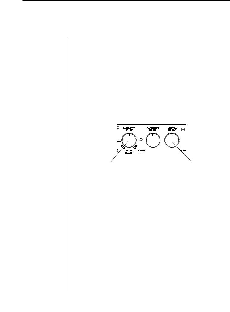
3. Front Panel
1
2
3
4
5
6
POWER switch
CONFIG button/led
This button briefly displays which configuration the current preset uses. After displaying the configuration, the Replifex™ will display the current preset number and title.
PRESET control
This control scrolls through and instantly recalls the successive presets.
TAP DELAY/RATE button
This button is used to select a new delay time or modulation rate based on the length of time occurring between two taps. See Section 7: "Tap Delay" for more information.
DISPLAY panel
The DISPLAY panel provides 16 characters consisting of 14 segments each.
COMPARE button
The COMPARE button may be used to compare an altered parameter value to its stored value.
Note: If comparing an altered value to the stored value and the stored value is currently being viewed, turning a knob or pressing a button that changes the parameter value displayed will cancel the previous altered value. This will also occur if a MIDI control change is received while viewing the stored value(s).
3

Front Panel Desccription
7 PARAMETER ADJUST control
This control is used to adjust the displayed parameter value. When the parameter is altered from its stored value, the LED above the STORE button will light until either (a) the new value is stored, (b) a new preset is selected or (c) the parameter is returned to its original value.
8 STORE button/led
This button is used to store parameter values into the Replifex™ memory when altered. See "Storing Changed Preset Parameters" in Chapter 7 for more information on this procedure.
9 |
PARAMETER SELECT control |
|
|
||
|
When adjusting parameter values, this control will scroll through |
||||
|
the available parameters under the current function heading. |
||||
|
In the "Title Edit" function, this control will scroll through the |
||||
|
character locations to be edited. |
|
|
||
1 0 |
FUNCTION SELECT control |
|
|
|
|
|
This control allows access to each function of the Replifex™ . These |
||||
|
functions include: |
|
|
|
|
|
Global |
Delay |
Chorus |
Channel Switches |
MIDI Channels |
|
Mixer |
Reverb |
Pitch Shift |
Title Edit |
MIDI Dump/Load |
|
HUSH |
Tremolo |
Rotary Speaker |
Controller Assig |
Factory Restore |
|
Compressor |
Phaser |
Auto Pan |
Copy |
Remote Control |
|
EQ |
Flanger |
Speaker Sim |
Program Changes |
Config Select |
1 1 BYPASS button/led
When lit, the effects are bypassed and only the input signal is passed to the Replifex™ outputs.
1 2 INPUT LEVEL meter
These LEDs provide visual indication of the peak level of the input signal when the preset number and title are displayed. For the optimal signal-to-noise ratio, it is best to adjust the input level so that the last LED (0dB) is rarely lit. This will guard against the possibility of overdriving the unit.
These LEDs also display the final digital mixer output levels when any other functions are displayed. This will help you to guard against clipping the output of the mixer at the digital-to-analog converter.
4

Front Panel DescriptionOperating the Replifex™ Operating the Replifex™
1 3 INPUT LEVEL control
This control adjusts the unit’s gain to match the signal level at the input of the Replifex™ . Use the INPUT LEVEL meter to determine the setting of this control.
1 4 OUTPUT LEVEL control and CLIP LED
This control is used to adjust the overall output level of the unit.
The CLIP L.E.D. is part of the output section and, when lit, indicates that the final analog output is being overdriven due to the Effects Level, Direct Level and Output Level being set too high. If this should occur, reduce these levels until the L.E.D. does not light.
1 5 REFERENCE LEVEL switch
This switch adjusts the output range of the unit and may be set at either -10dB or +4dB. When using the Replifex™ with professional studio equipment providing a nominal input level of +4dB, it is recommended that the +4 setting is used for best results. If the Replifex™ is to be connected to a high sensistivity input, such as the input to a guitar amp, the -10 setting should be used.
5
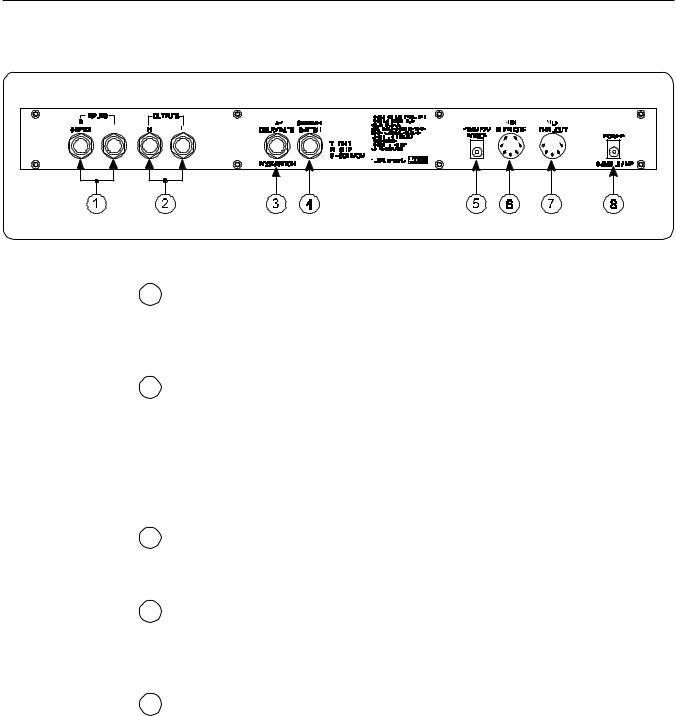
4. Rear Panel
|
|
|
|
|
|
|
|
|
|
|
|
|
|
|
|
1 |
Left and Right INPUT jacks |
||||||
|
These ¼" mono jacks provide inputs to the left and right channels |
||||||
|
of the Replifex™ . When using only one input, the Right (R) jack |
||||||
|
should be used. |
||||||
2 |
Left and Right OUTPUT jacks |
||||||
|
These ¼" mono jacks provide outputs from the left and right |
||||||
|
channels of the Replifex™ . |
||||||
|
When using a mono input (Right channel INPUT jack) and a mono |
||||||
|
output (either OUTPUT jack), the left and right effected signals |
||||||
|
will be summed at the single output. |
||||||
3 |
Tap Delay/Rate FOOTSWITCH jack |
||||||
|
This ¼" mono jack is provided for the connection of a momentary |
||||||
|
footswitch to control the Tap Delay feature of the Replifex™ . |
||||||
4 |
CHANNEL SWITCH jack |
||||||
|
This ¼" stereo jack can be connected to the channel switching |
||||||
|
footswitch jack on an amplifier or preamp. This allows for pro- |
||||||
|
grammable channel switching directly from the Replifex™ . |
||||||
|
. |
|
|
|
|
|
|
5 |
PHANTOM POWER jack |
||||||
|
This 2.5mm PIN jack offers the ability to power Rocktron MIDI |
||||||
foot controllers from a 7-pin MIDI cable which connects from the Rocktron MIDI foot controller to the MIDI IN jack on the rear panel of the Replifex™ . This eliminates the need to find an AC outlet near where the footpedal would be placed during a performance, or the need to run an extension cord out to the footswitch. Instead of inserting the AC adaptor into the "POWER" jack of the footswitch as you would normally, plug it into the "PHANTOM POWER" jack on the Replifex™ . This will power the Rocktron MIDI foot controller through pins 6 and 7 of the MIDI cable connecting the two units. A 7-pin MIDI cable must be used and is available from your Rocktron dealer.
6

Rear Panel Description
6 MIDI IN/REMOTE jack
This 7-pin DIN connector must be connected to the MIDI OUT jack of the transmitting MIDI device via a standard MIDI cable, or to the MIDI THRU jack of the preceding MIDI device (if the Replifex™ is within a chain of MIDI devices). Pins 6 and 7 of this connector carry phantom power to power a Rocktron MIDI foot controller when a 7-pin MIDI cable is used.
This connector is also provided for the connection of a Rocktron All Access™ MIDI footswitch, which can be configured as a dedicated remote footswitch for the Replifex™ . This feature allows the user to access Replifex™ functions and parameters via the remote footswitch.
7 MIDI THRU/OUT jack
This standard 5-pin DIN connector can be connected to the MIDI IN jack of another device via a standard MIDI cable. There are limitations to the number of devices that can be chained (or series connected) in this fashion.
Note: Inherently in MIDI there is a limit to the number of devices which can be chained together (connected in series). With more than 3 devices, a slight distortion of the MIDI signal can occur (due to signal degradation) which can cause an error in MIDI signal transmission. Should this problem arise, a MIDI Thru box can be used which connects directly to the MIDI device which transmits MIDI information and has multiple connectors for the multiple devices receiving MIDI. MIDI cables should not exceed 50 feet (15 meters) in length.
8 POWER jack
This 2.5mm pin jack accepts power from the 9VAC adaptor supplied with the unit.
7
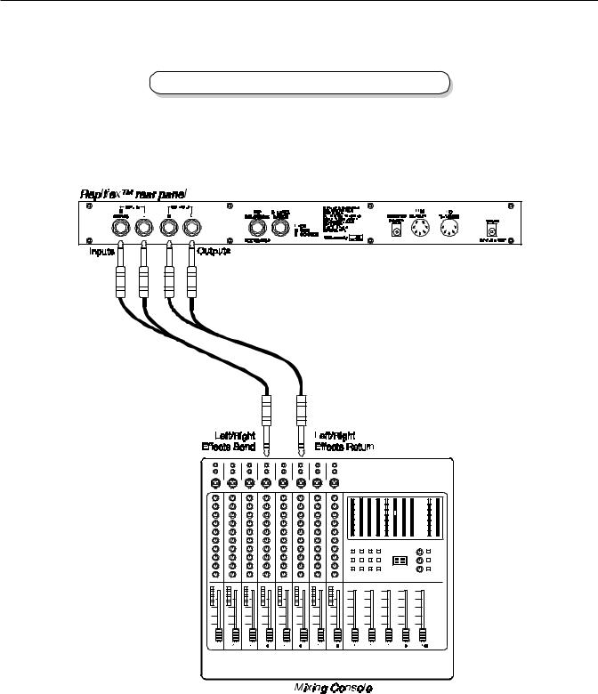
5. Connections
Using the Replifex™ within a guitar rack system
8

Using the Replifex™ in a preamp effects loop
9
Connections
Using the Replifex™ with a mixing console
10

6. Operating Format
The Replifex™ provides 128 stored sounds called presets. Any of the 128 presets can be called up at any time via the front panel PRESET control (used to both select and recall a preset).
The root of each preset’s sound is its configuration. The Replifex™ provides two main effect configurations - the Classic configuration and the Rotary configuration. Each configuration provides a different selection of available effects.
Classic configuration provides these effects:
• HUSH® |
• Reverb |
• Delay |
|||
• Parametric EQ |
• Compression |
• Phaser |
|||
• |
Flanger |
• |
Tremolo |
• |
Pitch Shift |
• |
Chorus |
• |
Auto Pan |
• |
Speaker Simulator |
Rotary configuration provides these effects:
• HUSH® |
• Reverb |
• Delay |
||
• |
Parametric EQ |
• |
Compression |
|
• |
Rotary Speaker |
• |
Speaker Simulator |
|
Any of the effects provided within a particular configuration may be switched in or out for each preset.
To see which configuration a given preset is utilizing, press the CONFIG button on the front panel of the Replifex™ - the display will show which configuration ("Classic" or "Rotary") is active for the current preset. The configuration type is displayed for a few seconds before returning to the current preset number and title.
The block diagrams on pages 12 and 13 illustrate the basic signal path for each configuration.
11

Block Diagrams
Classic Configuration
Block Diagram
12
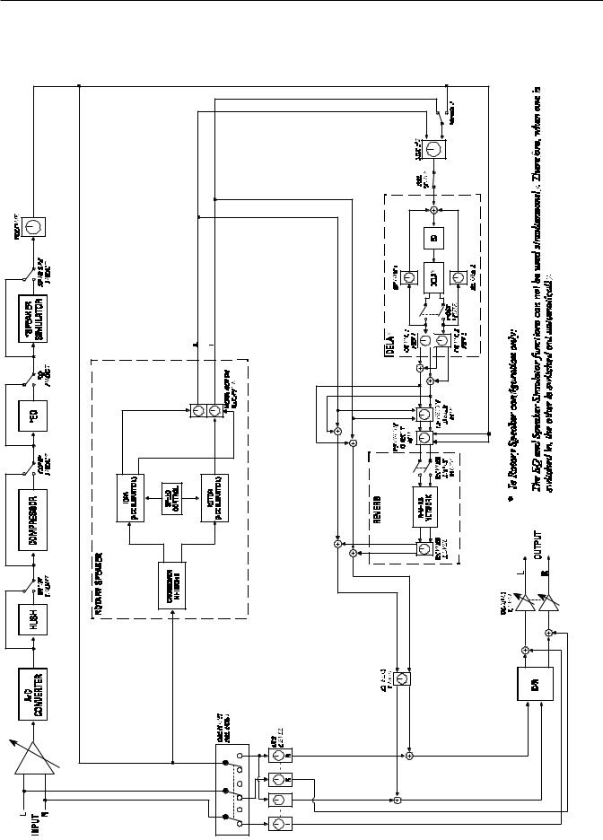
Block Diagrams
Rotary Configuration
Block Diagram
13
Functions and Parameter Descriptions
Replifex™ Functions and Parameter Descriptions
Each Replifex™ preset is divided into individual blocks called functions (such as "Mixer", "Reverb", etc.). Within each function is a set of controls which allow you to manipulate various aspects of that function. These controls are called parameters. The setting of each of the parameters determines the overall sound of each Replifex™ preset.
The Replifex™ user interface is set up to allow you to first access each function (via the FUNCTION SELECT control), then the list of available parameters for the selected function (via the PARAMETER SELECT control) and, finally, the adjustable value for each parameter (via the PARAMETER ADJUST control).
|
|
|
|
|
|
|
|
|
|
|
|
|
|
|
|
|
|
|
|
|
|
|
|
|
|
|
|
|
|
|
|
|
|
|
|
|
|
|
|
|
|
|
|
|
|
|
|
|
|
|
|
|
|
|
|
|
|
|
|
|
|
|
|
|
|
|
|
|
|
|
|
|
|
|
|
|
|
|
|
|
|
|
|
|
|
|
|
|
|
|
|
|
|
|
|
|
|
|
|
|
|
|
|
|
|
|
|
|
|
|
|
|
|
|
|
|
|
|
|
|
|
|
|
|
|
|
|
|
|
|
|
|
|
|
|
|
|
|
|
|
|
|
|
|
|
|
|
|
|
|
|
|
|
|
|
|
|
|
|
|
|
|
|
|
|
|
|
|
|
|
|
|
|
|
|
|
|
|
|
|
|
|
|
|
|
|
|
|
|
|
|
|
|
|
|
|
|
|
|
|
|
|
|
|
|
|
|
|
|
|
|
|
|
|
|
|
|
|
|
|
|
|
|
|
|
|
|
|
|
|
|
|
|
|
|
|
|
|
|
|
|
|
|
|
|
|
|
|
|
|
|
|
|
|
|
|
|
|
|
|
|
|
|
|
|
|
|
|
|
|
|
|
|
|
|
|
|
|
|
|
|
|
|
|
|
|
|
|
|
|
|
|
|
|
|
|
|
|
|
|
|
|
|
|
|
|
|
|
|
|
|
|
|
|
|
|
|
|
|
|
|
|
|
|
|
|
|
|
|
|
|
|
|
|
|
|
|
|
|
|
|
|
|
|
|
|
|
|
|
|
|
|
|
|
|
|
|
|
|
|
|
|
|
|
|
|
|
|
|
|
|
|
|
|
|
|
|
|
|
|
|
|
|
|
|
|
|
|
|
|
|
|
|
|
|
|
|
|
|
|
|
|
|
|
|
|
|
|
|
|
|
|
|
|
|
|
|
|
|
|
|
|
|
|
|
|
|
|
|
|
|
|
|
|
|
|
|
|
|
|
|
|
|
|
|
|
|
|
|
|
|
|
|
|
Step 3: |
|
|
|
|
|
|
|
|
Step 2: |
|
|
|
|
|
Step 1: |
|||||||||||||||||||
Turn to alter the value of the |
|
|
|
Turn to select a parameter |
|
Turn to select a function. |
||||||||||||||||||||||||||||
selected parameter. |
|
|
within the selected function. |
|
|
|
|
|
|
|||||||||||||||||||||||||
The remainder of this section will discuss each of the effect-based functions and the associated adjustable parameters that they provide. Functions not discussed in this section are utility-based, and are described in Section 7, "Operating the Replifex™".
14

Functions and Parameter Descriptions
GLOBAL
Function
The first function displayed when turning the FUNCTION SELECT control is the Global function. The parameters provided in this function affect all presets (i.e. the settings stored for these parameters are the same for all presets).
The PARAMETER SELECT control will allow you to access each of the following Global parameters:
OUTPUT |
The OUTPUT parameter determines whether the output of the |
|
Replifex™ is a stereo (left and right) signal or two mono signals. |
HUSH OFFSET |
The HUSH OFFSET parameter allows you to globally (all presets) |
|
adjust the HUSH® Expander Threshold. This means that if this param- |
|
eter is altered from 0dB to +3dB, the Expander Threshold will be 3dB |
|
higher for all presets. This feature can be useful when switching from a |
|
quiet guitar with passive electronics to a noisy guitar with active |
|
electronics - as the active guitar would require a higher Threshold level |
|
in all presets. |
MUTE |
The MUTE parameter allows you to mute the output of the Replifex™ . |
|
This feature is especially useful when changing guitars during a live set. |
|
When the Replifex is muted, front panel controls are disabled. However, |
|
a MIDI program change will disable the mute (mute = out) and execute |
|
the program change. |
|
The MUTE parameter can be assigned to a MIDI controller number for |
|
use with a MIDI device (such as a Rocktron All Access™ or Rocktron |
|
MIDI Mate™ ). |
DIRECT |
The DIRECT parameter determines whether the direct signal is |
|
switched in or out of the signal path. When using the Replifex™ in |
|
applications where the unit is connected in parallel, it is recommended |
|
that the direct signal is switched out - thereby providing 100% wet |
|
(effect) output. |
15

Functions and Parameter Descriptions
MIXER
Function
The next function displayed when turning the FUNCTION SELECT control is the Mixer function. The Mixer function parameters are included in all presets - regardless of which effects are active for the current preset - although the parameter values stored in this function are only for the currently recalled preset.
This digital mixer allows you to control the signal levels pertaining to each preset’s configuration and stores those levels for each preset.
The PARAMETER SELECT control will allow you to access each of the following Mixer parameters:
LEFT DIR |
The LEFT DIRECT parameter determines the level of the direct signal |
|
of the current preset at the left output. |
RIGHT DIR |
The RIGHT DIRECT parameter determines the level of the direct |
|
signal of the current preset at the right output. |
EFFECT LEVEL |
The EFFECT LEVEL parameter determines the volume of the overall |
|
effect signal (Chorus, Flange, Pitch Shift, etc.) level. |
DIRECT |
The DIRECT parameter determines whether the direct signal is pre- |
|
HUSH or post-HUSH. When set to pre-HUSH, the direct signal is not |
|
passed through the HUSH circuitry, or any other digital circuitry (i.e., |
|
the direct signal remains analog from input to output. When set to post- |
|
HUSH, the direct signal is passed through the digital HUSH circuitry. |
PHS DIR/EFF |
These DIR/EFF parameters determine the amount of direct signal input |
CHR DIR/EFF |
to each individual effect relative to the amount of effect signal. A |
FLN DIR/EFF |
setting of "0" is 100% direct signal, while a setting of "100" is 100% |
REV DIR/EFF |
effect signal. |
VOLUME |
The VOLUME parameter determines the overall signal level of the |
|
current preset. |
16

Functions and Parameter Descriptions
HUSH
Function
The HUSH® function is accessible in all presets - regardless of the configuration currently recalled.
HUSH® is Hush Systems’ patented single-ended noise reduction system. The HUSH system contained in the Replifex™ is a fully digital implementation of HUSH achieved through Digital Signal Processing (DSP), and is modeled after the latest HUSH design.
The low level expander of the HUSH system operates like an electronic volume control. The analog version of the HUSH utilizes a voltage-controlled amplifier (VCA) circuit which can control the gain between the input and the output from unity to 30, 40 or even 50dB of gain reduction. When the input signal is above the user preset threshold point, the VCA circuit remains at unity gain. (This means that the amplitude of the output signal will be equal to that of the input signal.) As the input signal level drops below the user preset threshold point, downward expansion begins. At this point the expander acts like an electronic volume control and gradually begins to decrease the output signal level relative to the input signal level. As the input signal drops further below the threshold point, downward expansion increases. A drop in the input level by 20dB would cause the output level to drop approximately 40dB (i.e., 20dB of gain reduction). In the absence of any input signal, the expander will reduce the gain so that the noise floor becomes inaudible.
The HUSH circuit is located after the A/D converter in the signal chain to reduce any noise generated from the guitar, any guitar preamp and the A/D converter. This ensures a quiet input signal to the Replifex™ effects.
When the DIRECT HUSH parameter under the Mixer function is set to "Post", the direct signal is passed through the HUSH circuit. When set to "Pre", the direct signal remains analog and does not pass through the HUSH circuit.
The PARAMETER SELECT control will allow you to access each of the following Hush parameters:
HUSH I/O |
The HUSH I/O parameter determines whether the HUSH® circuit is |
|
active or bypassed for the current preset. |
EXP THRESH |
The EXPANDER THRESHOLD parameter determines the level at |
|
which downward expansion begins. For example, if the EXPANDER |
|
THRESHOLD was set at -20dB and the input signal dropped below |
|
-20dB, downward expansion would begin. |
17
Functions and Parameter Descriptions
COMPRESSOR
Function
Compression is often used to maintain an even level when using clean tones, and is also used to increase sustain when using high gain distortion.
The PARAMETER SELECT control will allow you to access each of the following Compressor parameters:
COMPRESR I/O The COMPRESSOR I/O parameter determines whether the compression circuit is active or bypassed for the current preset.
COMP THRESH The COMPRESSOR THRESHOLD parameter determines the input level (in dB) at which compression will begin. Lower settings of this parameter will result in more compression.
COMP ATTACK The COMPRESSOR ATTACK parameter determines the speed (in milliseconds) at which the compressor will reach its maximum compression level after the input signal has exceeded the threshold level (set by the COMPRESSOR THRESHOLD parameter).
COMP RELEASE The COMPRESSOR RELEASE parameter determines the speed at which compression will cease after the input signal has dropped below the threshold level.
18

Functions and Parameter Descriptions
EQ
Function
The EQ function provides full parametric control and allows you shape the tone of the input signal before it reaches each of the effect blocks.
The PARAMETER SELECT control will allow you to access each of the following EQ parameters:
EQ I/O |
The EQ I/O parameter determines whether the EQ circuit is active or |
|
bypassed for the current preset. |
BASS LVL |
The BASS LEVEL parameter allows you to cut or boost the low |
|
frequencies by up to 15dB. |
BASS FREQ |
The BASS FREQUENCY parameter allows you to select a center |
|
frequency between 63Hz and 500Hz to be cut or boosted by the BASS |
|
LEVEL parameter. |
BASS BW |
The BASS BANDWIDTH parameter determines (in octaves) the width |
|
of the selected bass band. |
MID LVL |
The MID LEVEL parameter allows you to cut or boost the mid band |
|
frequencies by up to 15dB. |
MID FREQ |
The MID FREQUENCY parameter determines a mid band center |
|
frequency between 250Hz and 2KHz to be cut or boosted via the MID |
|
LEVEL parameter. |
MID BW |
The MID BANDWIDTH parameter determines (in octaves) the width |
|
of the selected mid band. |
TREBLE LVL |
The TREBLE LEVEL parameter allows you to cut or boost the high |
|
band frequencies by up to 15dB. |
TREBL FRQ |
The TREBLE FREQUENCY parameter determines a high band center |
|
frequency between 1KHz and 8KHz to be cut or boosted via the |
|
TREBLE LEVEL parameter. |
TREBLE BW |
The TREBLE BANDWIDTH parameter determines (in octaves) the |
|
width of the selected high band. |
PRESENCE LVL |
The PRESENCE LEVEL parameter allows you to cut or boost an |
|
additional high band frequency by up to 15dB. |
PRES FREQ |
The PRESENCE FREQUENCY parameter allows you to select a high |
|
band center frequency between 2KHz and 8KHz to be cut or boosted |
|
via thePRESENCE LEVEL parameter. |
PRES BW |
The PRESENCE BANDWIDTH parameter determines (in octaves) the |
|
width of the selected high band. |
19

Functions and Parameter Descriptions
DELAY
Function
Delay provides a reproduction of the input signal, occurring at a prescribed time (usually expressed in milliseconds) following the input signal. The Replifex™ provides two discrete delays (Delay 1 and Delay 2), each of which has its own set of parameters to determine its particular characteristics.
The PARAMETER SELECT control will allow you to access each of the following Delay parameters:
DELAY I/O |
The DELAY I/O parameter determines whether the delay circuit is |
|
active or bypassed for the current preset. |
MUTE TYPE |
The MUTE TYPE parameter allows for muting the delay at its input |
|
(PRE), its output (POST) or BOTH. |
|
Muting the input (PRE) of the delay will not allow any signal to enter |
|
the delay section until the delay is switched in. When using a moderate |
|
amount of regeneration, switching out the delay with the input muted |
|
will allow you to generate a non-delayed signal which will play over the |
|
decaying regenerated signal which continues on after the delay is |
|
switched out. |
|
Muting the output (POST) of the delay will result in the delayed signal |
|
being immediately turned off when the delay is switched out. This |
|
means that delays and regeneration will not continue when the delay is |
|
switched out. If the output were not muted, signals that were input |
|
before the delay was switched out would be allowed to regenerate, even |
|
after switching out the delay. |
|
It is also possible to mute both the input and the output (BOTH) so that |
|
no signal enters or exits the Delay section until it is switched in. |
TIME1 |
The TIME1 parameter determines the multiplier by which a new delay |
|
time will be selected for Delay Time 1 when the Tap Delay feature of |
|
the Replifex™ is used. (See Section 7: "Tap Delay" for more information |
|
on the Tap Delay feature.) |
TIME2 |
The TIME2 parameter determines the multiplier by which a new delay |
|
time will be selected for Delay Time 2 when the Tap Delay feature of |
|
the Replifex™ is used. (See Section 7: "Tap Delay" for more information |
|
on the Tap Delay feature.) |
DELAY LVL |
The DELAY LEVEL parameter determines the overall level of the |
|
delayed signal at the output of the Replifex™ . |
D-MIX S1/S2 |
The D-MIX S1/S2 parameter defines the ratio of Source 1 signal to |
|
Source 2 signal to be input to the Delay section. Source 1 is the Voice 1 |
|
output from the previous effect in the signal chain (chorus, flanger, |
|
pitch shifter, etc.), while Source 2 may be the Voice 2 output from the |
|
previous effect in the signal chain or the direct signal (selectable via the |
|
SOURCE 2 parameter). (Refer to the block diagrams shown on pages |
|
12 and 13 for a visual representation of the input to the Delay section.) |
20
 Loading...