

Page 1

cobas b 221 system
Instructions for Use
Page 2

COBAS, COBAS B and LIFE NEEDS ANSWERS
are trademarks of Roche.
Roche Diagnostics GmbH
D-68298 Mannheim
Germany
www.roche-diagnostics.com
©2009 Roche Diagnostics
Page 3

cobas b 221 system
Revision History
Manual Version Software Version Revision date Changes
2.0 1.0 May 2003 Launch
3.0 1.0 June 2003 not delivered
3.1 1.02 July 2003
4.0 2.0 March 2004
5.0 4.0 December 2004
6.0 5.0 November 2005
7.0 5.0 March 2006 cobas Branding
8.0 6.0 December 2006
9.0 7.0 February 2008
10.0 >7.0 April 2009
Edition notice
Copyright
cobas b 221 system
In the course of 2006 the Roche OMNI S system was relaunched under the
Roche Diagnostics professional IVD user brand cobas®.
Systems with a serial number of 5001 or above are cobas b 221 systems.
Systems with a serial number up to 5000 are Roche OMNI S systems.
Every effort has been made to ensure that all the information contained in this
manual is correct at the time of printing. However, Roche Diagnostics GmbH reserves
the right to make any changes necessary without notice as part of ongoing product
development.
Any customer modification to the instrument will render the warranty or service
agreement null and void.
Software updates are done by Roche Service representatives.
© 2009, Roche Diagnostics GmbH, all rights reserved
The contents of this document may not be reproduced in any form or communicated
to any third party without the prior written consent of Roche Diagnostics.
While every effort is made to ensure its correctness, Roche Diagnostics assumes no
responsibility for errors or omissions which may appear in this document.
Subject to change without notice.
Roche Diagnostics April 2009
Instructions for Use · Revision 10.0 1
Page 4

Brands
Contact addresses
cobas b 221 system
COBAS, COBAS B, LIFE NEEDS ANSWERS, ROCHE OMNI, AUTOQC,
ROCHE MICROSAMPLER, COMBITROL and AUTO-TROL are trademarks of
Roche.
Edition
Manufacturer
Roche Diagnostics GmbH
D-68298 Mannheim / Germany
www.roche.com
Revision 10.0, April 2009
First edition: May 2003
REF/No. 03261395001
Roche Diagnostics April 2009
2 Instructions for Use · Revision 10.0
Page 5

cobas b 221 system
Table of contents
Revision History 1
Edition notice 1
Copyright 1
Brands 2
Contact addresses 2
Edition 2
Tab l e o f co n ten t s 3
Preface 5
How to use this manual 5
Where to find information 5
Conventions used in this manual 5
Introduction and specifications Part A
1 Safety information
Important information A-5
Operating safety information A-6
2 General descriptions
Introduction A-9
General notes A-11
Measurement and calibration procedure A-13
Measurement evaluation A-14
Safety instructions for specific dangers A-14
Handling solutions A-15
Handling electrodes A-15
General notes on the use of the MSS cassette A-16
System description A-18
Operation Part B
6 Measurement
Preanalytics B-5
Interferences B-10
Limitations of clinical analysis B-17
Measuring procedure B-19
7 Quality control
Quality control - general B-33
General QC concept B-33
Important information concerning the analysis of QC
measurement results B-35
Material setup B-36
QC setup wizard B-44
QC measurement B-51
Multirules B-53
QC consequences B-55
Remove the QC lock B-56
QC for Ready (with AutoQC module) B-57
QC for Ready (without AutoQC module) B-59
QC troubleshooting B-61
8Calibration
Calibration - general B-65
Automatic calibrations B-65
User-activated calibrations B-66
Display of parameters during calibration B-68
3 Installation and shutdown
Installation A-27
Shutdown A-48
9 Software modes
Software modes - general B-71
User interface B-71
Analyzer mode B-78
4 Specifications
Performance data A-59
Sample throughput A-86
Setup B-80
Data manager B-81
Info B-87
Measurement times of the samples A-86
Sample volumes A-87
Sample types A-87
Maintenance Part C
Calibrations A-88
Environmental parameters A-89
Product data A-91
AutoQC A-92
Printer A-92
Touch screen-PC unit A-93
Barcode scanner A-94
10 Maintenance
Maintenance - general C-5
Decontamination C-5
Daily C-7
Weekly C-8
Quarterly C-9
Sample-dependent maintenance procedures C-13
5 Theoretical foundations
Parameters and calculations A-97
Unscheduled C-22
Additional maintenance procedures C-38
Clinical significance A-109
Roche Diagnostics April 2009
Instructions for Use · Revision 10.0 3
Page 6

Troubleshooting Part D
11 Troubleshooting
Troubleshooting - general D-5
System stops D-5
Module stops D-12
System warnings D-16
Status messages of measuring and calibration values
D-20
Status messages on the measurement report D-39
Barcode D-40
Appendix Part E
12 List of consumables
Order information E-5
Glossary E-9
cobas b 221 system
Index Part F
Index F-3
Roche Diagnostics April 2009
4 Instructions for Use · Revision 10.0
Page 7

cobas b 221 system
Preface
The cobas b 221 system is an analyzer with integrated AutoQC drawer option.
This manual has detailed descriptions of cobas b 221 system features and general
operational concepts, specification functions and use of controls, operating
techniques, emergency procedures, product labeling and maintenance procedures.
How to use this manual
o
Keep this manual in a safe place to ensure that it is not damaged and remains available for use.
o
This Instructions for Use should be easily accessible at all times.
To help you find information quickly, there is a table of contents at the beginning of
the book and each chapter. In addition, a complete index can be found at the end.
Where to find information
In addition to the Instructions for Use, the following documents are also provided to
assist in finding desired information quickly:
o cobas b 221 system Reference Manual
o cobas b 221 system Short Instruction
Conventions used in this manual
Visual cues are used to help locate and interpret information in this manual quickly.
This section explains formatting conventions used in this manual.
Symbols Helping to locate and interpret information in this manual the following symbols are
used:
Symbol Used for
a Procedural step
o List item
e
h Call up of screen
Cross-reference
Note
Roche Diagnostics April 2009
Instructions for Use · Revision 10.0 5
Page 8
Symbol Used for
Caution
All sections / passages that are marked with this symbol describe procedures
and/or indicate conditions or dangers that could damage or lead to a
malfunction in the cobas b 221 system, and which therefore should never be
attempted and contain information that must be observed to avoid potential
injuries (to patients, users and third parties).
Risk of infection
All sections and parts of texts that are marked with this symbol describe
procedures that may involve risk of infection.
cobas b 221 system
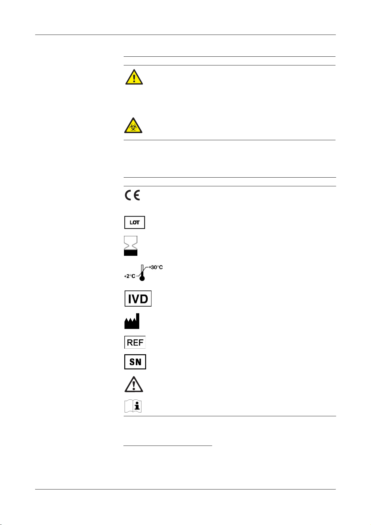
IVD symbols The symbols are used in accordance with DIN EN 980
Symbol Description
Conformité Européenne:
This product complies with the requirements in the guideline for
In Vitro Diagnostic 98/79/EC.
Lot designation
Use by...
The product should not be used after expiry of the specified date.
If a day is not indicated, apply the last day of the respective month.
Temperature limitation
The conditions necessary to preserve the product's shelf life before
opening.
In Vitro Diagnostic Medical Device
Manufacturer
(according to In Vitro Diagnostic guidelines 98/79/EG)
Catalogue number
(a)
and DIN EN ISO 780
(b)
.
Serial number (model plate)
Caution, consult accompanying documents
Please consult instructions for use
(a) DIN EN 980: Medical devices - Symbols to be used with medica l device labels, labelling and information
to be supplied (Part 1: General requirements)
(b) DIN EN ISO 780: Packaging - Pictorial marking for the handling of goods
Roche Diagnostics April 2009
6 Instructions for Use · Revision 10.0
Page 9
cobas b 221 system
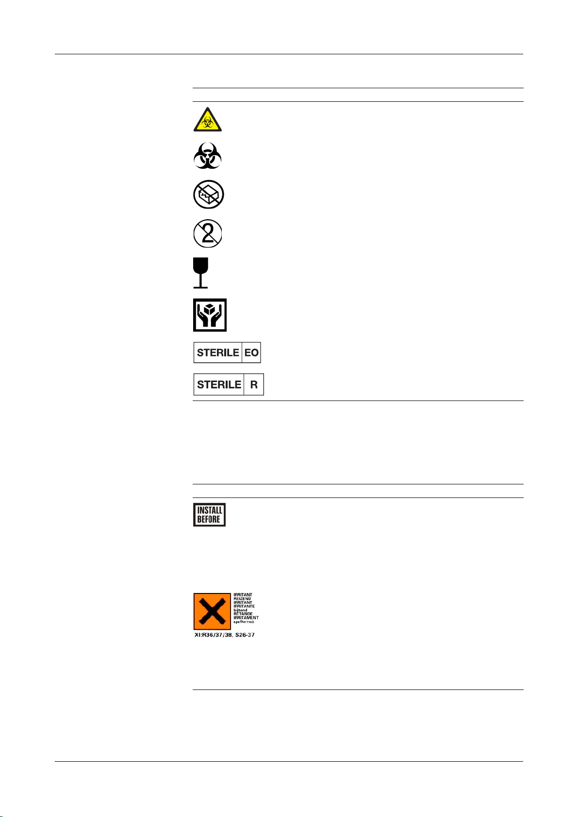
Symbol Description
Biological risk!
(according to the standard IEC/EN 61010-2-101)
Biological risk!
(according to the standard DIN EN ISO 980)
Do not use if package damaged
Do not reuse
Fragile. Handle with care
Handle with care
(a)
(Instrument)
(b)
(Consumables)
Valid only for Roche MICROSAMPLER:
Method of sterilization using ethylene oxide
Valid only for BS2 Blood Sampler:
Method of sterilization using irradiation
(a) IEC/EN 61010-2-101: Safety requirements for electrical equipment for measurement, control, and
laboratory use - (Part 2-101: Particular requirements for in vitro diagnostic (IVD) medical equipment).
(b) DIN EN ISO 980: Medical devices - Symbols to be used with medical device labels, labelling and
information to be supplied (Part 1: General requirements).
Other symbols The following symbols are listed as additional information:
Symbol Description
Electrodes:
This date indicates the limit of the maximum storage time of
an electrode. The electrode must be installed in the instrument
no later than the imprinted date.
If the installation takes place on the imprinted date, it still falls
within the specifications. The calculation of the “Install
before” date is based on the production date of the elctrode.
Danger symbol: "Irritant" (on the label and the packaging of
S2 Fluid Pack)
Rating: Although not corrosive, momentary, longer-lasting, or
repeated contact with skin or mucous membrane may result in
inflammation. Danger of sensitization during contact with
skin (when classified with R 43).
Caution: Avoid contact with eyes and skin, do not inhale
vapors.
Roche Diagnostics April 2009
Instructions for Use · Revision 10.0 7
Page 10
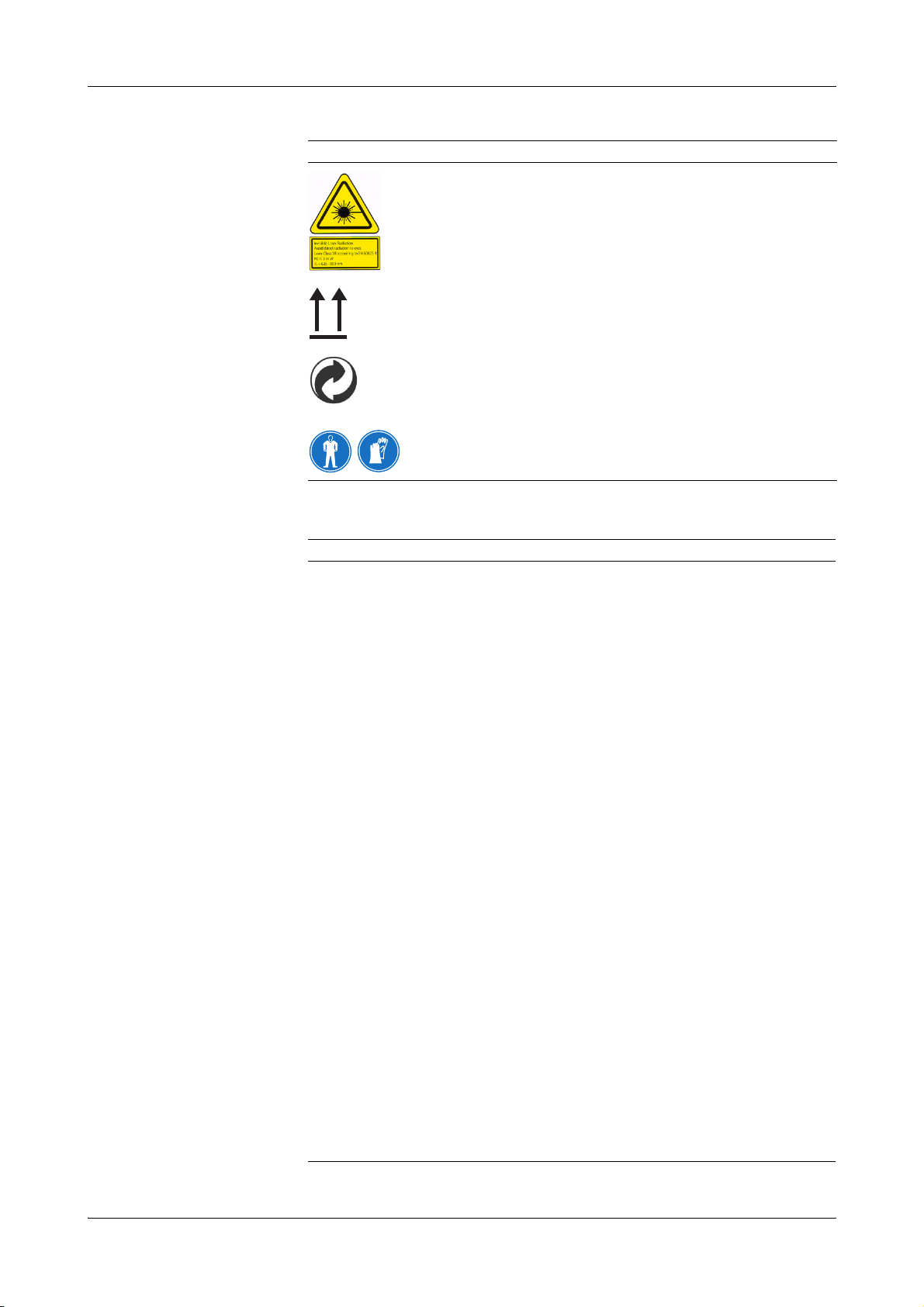
Symbol Description
Invisible Laser Radiation
Avoid direct radiation to eyes!
Laser Class 3R according to EN 60825-1
P0 ≤ 5 mW
λ = 635 - 850 nm
Store upright
"Grüner Punkt" (in Germany)
Protective gloves, protective goggles and suitable protective
clothing must be worn.
Abbreviations The following abbreviations are used:
cobas b 221 system
Abbreviation Definition
A
ANSI American National Standards Institute
AQC Automatic Quality Control
B
BG Blood gas
BUN Abbr. for blood urea nitrogen
C
CLIA Clinical Laboratory Improvement Amendments
CLSI Clinical and Laboratory Standards Institute
cond Conductivity
CSA Canadian Standards Association
D
dBA Decibel weighted against the A-frequency response curve. This curve
approximates the audible range of the human ear.
DIL Diluent
DNS Domain Name Server
E
EC European community
e.g. exempli gratia – for example
EN European standard
F
FMS Fluid mixing system
H
Hct Hematrocrit
HIV Human immunodeficiency virus
HW Hardware
Roche Diagnostics April 2009
8 Instructions for Use · Revision 10.0
Page 11

cobas b 221 system
Abbreviation Definition
I
i.e. id est – that is to say
ISE Ion selective electrode
IVD In vitro Diagnostic Directive
L
LCD Liquid cristal display
LIS Laboratory Information System
LJ Levey Jennings
M
MAC Media Access Control
MC Measuring chamber
MSDS Material safety data sheet
MSS Metabolite sensitive sensor
MV Mean value
P
PP Peristaltic pump
Q
QC Quality control
R
RCon Reference contact
REF Reference solution
S
SIP Sample inlet path
SDC Sample distributor cartridge
S1 S1 Rinse Solution
S2 S2 Fluid Pack
S3 S3 Fluid Pack
SCon Sensor contact
SD Standard deviation
SO
T
2
Oxygen saturation
T&D Turn & dock
tHb Total hemoglobin
U
UL Underwriters Laboratories Inc.
V
VDE Association of German Electrical Engineers (Verband Deutscher
Elektrotechniker)
e
For writing the measuring, calculated and input values see Chapter 9 Softwaremodi >
Parameter on page B-75!
Roche Diagnostics April 2009
Instructions for Use · Revision 10.0 9
Page 12

cobas b 221 system
Roche Diagnostics April 2009
10 Instructions for Use · Revision 10.0
Page 13

Introduction and specifications
1 Safety information . . . . . . . . . . . . . . . . . . . . . . . . . . . . . . . . . . . A-3
2 General descriptions . . . . . . . . . . . . . . . . . . . . . . . . . . . . . . . . . A-7
3 Installation and shutdown . . . . . . . . . . . . . . . . . . . . . . . . . . . . A-25
4 Specifications . . . . . . . . . . . . . . . . . . . . . . . . . . . . . . . . . . . . . . . A-57
5 Theoretical foundations . . . . . . . . . . . . . . . . . . . . . . . . . . . . . . . A-95
A
Page 14

Page 15

cobas b 221 system 1 Safety information
Contents
Safety information
The information provided in this chapter is essential for the safe, trouble-free
operation of the instrument and must be read and understood by the user.
In this chapter
Important information ...................................................................................................5
Operating safety information .........................................................................................6
Chapter
1
Roche Diagnostics April 2009
Instructions for Use · Revision 10.0 A-3
Page 16

1 Safety information cobas b 221 system
Contents
Roche Diagnostics April 2009
A-4 Instructions for Use · Revision 10.0
Page 17
cobas b 221 system 1 Safety information
Important information
Important information
These Instructions for Use contain vital warnings and safety information.
This instrument is intended to be used only for the specialized purpose described in
the instructions. The most important prerequisites for use, operation, and safety are
explained to ensure smooth operation. No warranty or liability claims will be covered
if the machine is used in ways other than those described or if the necessary
prerequisites and safety measures are not observed.
The instrument may be operated only by persons whose qualifications enable them to
comply with the safety measures that are necessary during operation of the
instrument.
Suitable protective equipment, like laboratory clothing, protective gloves, protective
goggles and if necessary mouth protectors, must be worn to prevent direct contact
with biological working materials. In addition, a face mask is required if there is a
risk.
Adjustments and maintenance performed with covers removed and power connected
may be attempted only by a qualified technician who is aware of the associated
dangers.
Instrument repairs are to be performed only by the manufacturer or qualified service
personnel.
Only accessories and supplies either delivered by or approved by Roche are to be used
with the instrument. These items are manufactured especially for use with this
instrument and meet the highest quality requirements.
Operation of the instrument with solutions whose composition is not consistent with
that of the original solutions can negatively affect the long-term measurement
accuracy. Deviations in the composition of the solutions can also decrease the service
life of the electrodes.
In order to ensure the quality of the measurement results, complete a quality control
test on 3 levels (low, normal, high) after each electrode exchange, after each exchange
of solutions and packs and after startup of the instrument.
Additionally complete a quality control test on one level between two automatic 2P
calibrations. The level have to be alternated (low, normal, high).
Since the measurements of the instrument depend not only on the correct
characteristic function, but also on a series of marginal conditions (e.g. pre-analysis),
results obtained from the instrument should be submitted for an expert opinion
before taking additional measures based on the supplied measurements.
Caution (refer to accompanying documents)!
Please refer to safety-related notes in the manual accompanying this instrument.
Roche Diagnostics April 2009
Instructions for Use · Revision 10.0 A-5
Page 18
1 Safety information cobas b 221 system
Operating safety information
Operating safety information
The instrument has been constructed and tested according to the following European
Standards:
o IEC/EN 61010-1
o IEC/EN 61010-2-101
o IEC/EN 61010-2-081 + A1
It was delivered from the factory in flawless condition with regards to safety features.
In order to preserve this condition and ensure safe operation, the user must respect
the notices and warnings that are contained in these Instructions for Use.
o This equipment is a Class I laser product, and it complies with FDA Radiation
Performance Standards, 21 CFR Subchapter J (only valid for
cobas b 221<1> system, cobas b 221<3> system and cobas b 221<5> system with
tHb/SO
o This instrument is classified under the protection class I according to
IEC /EN 61010-1.
o The instrument meets the conditions for overvoltage category II.
o The instrument meets the conditions for contamination level 2.
o Do not operate the instrument in an explosive environment or in the vicinity of
explosive anesthetic mixtures containing oxygen or nitrous oxide.
o If objects or liquids enter the internal areas of the instrument, remove the
instrument from its power supply and allow an expert to check it thoroughly
before using it again.
o The instrument is suitable for long-term operation indoors.
module).
2
o
The power cord must be plugged into a grounded power receptacle. When using an extension
cord, make sure it is properly grounded.
o
Any rupture of the ground lead inside or outside the instrument or a loose ground connection
may result in hazardous operating conditions for the operating personnel. Intentional
disconnection of the grounding is not permitted.
o
The instrument is not suitable for operation with a direct current power supply. Use only the
original power plug delivered with the cobas b 221 system.
o
The use of controls or adjustments or performance of procedures other than those specified
herein may result in hazardous radiation exposure.
Roche Diagnostics April 2009
A-6 Instructions for Use · Revision 10.0
Page 19

cobas b 221 system 2 General descriptions
Contents
General descriptions
This chapter contains a general description of the instrument, as well as
precautionary measures against special dangers and the proper handling of sensors,
solutions and the MSS cassette.
In this chapter
Introduction ....................................................................................................................9
General notes .................................................................................................................11
Application area .......................................................................................................11
Operating instructions ............................................................................................ 11
Important buttons on the screen ............................................................................ 12
Measurement and calibration procedure ..................................................................... 13
Measurement procedure .........................................................................................13
Calibration procedure ............................................................................................. 13
Measurement evaluation ...............................................................................................14
Safety instructions for specific dangers ........................................................................ 14
Handling samples .................................................................................................... 14
Disposal of waste water, bottles, packs, electrodes and the instrument ...............14
Decontamination ....................................................................................................14
Handling solutions ........................................................................................................ 15
Handling electrodes ......................................................................................................15
General notes on the use of the MSS cassette ..............................................................16
MSS cassette removed from the measuring chamber ............................................ 16
Incompatible substances ......................................................................................... 16
Inserting the MSS cassette ......................................................................................17
System description ........................................................................................................ 18
Visual identification ................................................................................................ 18
Screen/PC unit ......................................................................................................... 19
Printer ......................................................................................................................19
Measuring chamber .................................................................................................19
tHb/SO
COOX module .........................................................................................................20
Pumps ......................................................................................................................20
Input unit ................................................................................................................. 20
module .....................................................................................................19
2
Chapter
2
Roche Diagnostics April 2009
Instructions for Use · Revision 10.0 A-7
Page 20

2 General descriptions cobas b 221 system
Contents
Bottle compartment ................................................................................................20
Reverse side .............................................................................................................. 21
Power supply ...................................................................................................... 21
Interfaces ............................................................................................................22
Barcode scanner ................................................................................................. 23
Warning and identification labels (incl. nameplate) .......................................24
Roche Diagnostics April 2009
A-8 Instructions for Use · Revision 10.0
Page 21
cobas b 221 system 2 General descriptions
Introduction
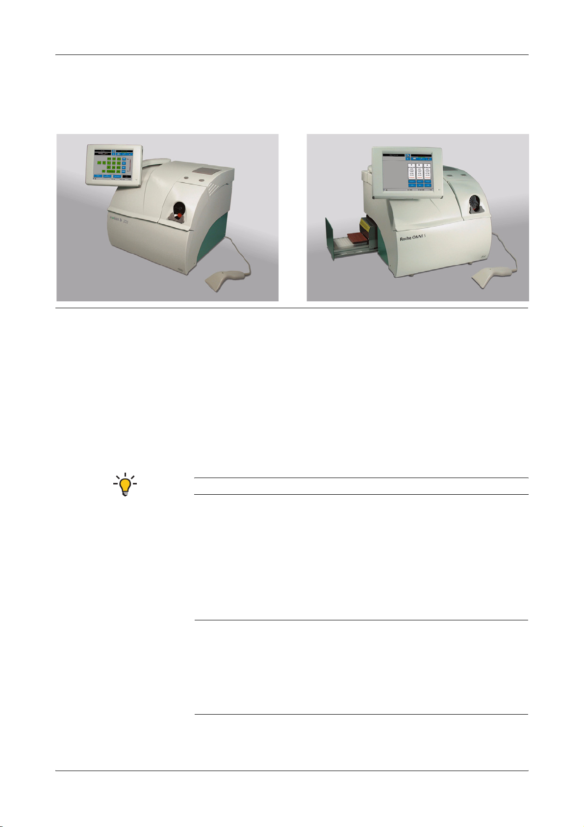
Introduction
Figure A-1 cobas b 221 system
The cobas b 221 system is an analyzer with integrated AutoQC drawer option.
Depending on combination and configuration, the following parameters can be
measured in whole blood, serum, plasma, acetate and bicarbonate containing dialysis
solutions and QC materials:
o pH
o Blood gas BG (PO
o Electrolyte ISE (Na
, PCO2)
2
+
, K+, Cl–, Ca2+)
o Hematocrit (Hct)
o Metabolite MSS
Urea/BUN - only cobas b 221<6> system
o To t al h em og lo b in ( tH b)
o Oxygen saturation (SO
o Hemoglobin derivative COOX (O
)
2
Hb, HHb, COHb, MetHb)
2
o Bilirubin (neonatal)
The following configurations are available:
o cobas b 221<1> system
(a)
BG, pH, tHb/SO
2
o cobas b 221<2> system BG, pH, COOX, Bili
o cobas b 221<3> system
(a)
BG, pH, ISE, Hct, tHb/SO2
o cobas b 221<4> system BG, pH, ISE, Hct, COOX, Bili
o cobas b 221<5> system
(a)
BG, pH, ISE, Hct, MSS, tHb/SO
2
o cobas b 221<6> system BG, pH, ISE, Hct, MSS, COOX, Bili
(a) are no longer manufactured or offered.
Roche Diagnostics April 2009
Instructions for Use · Revision 10.0 A-9
Page 22

2 General descriptions cobas b 221 system
Introduction
During the measurement or calibration or other processes, it is possible to conduct
database operations, perform certain settings or call up general information at the
same time.
e
For details see Chapter 9 Software modes
The individual, mutually independent software modes are defined as follows:
o Analyzer Measuring, QC measurement, system, calibration,
commonly used functions (quick access)
o Setup Instrument settings
o Database Data about patients, measurements, calibrations, QC, and
the instrument
o Info
Roche Diagnostics April 2009
A-10 Instructions for Use · Revision 10.0
Page 23

cobas b 221 system 2 General descriptions
General notes
General notes
Application area
The instrument has been tested for measuring parameters in whole blood, serum,
plasma and dialysis solutions (electrolytes only) and the validity of measurements was
tested accordingly.
In order to achieve accurate measurements of recommended aqueous control
solutions (with regards to deviations from biological samples), choose the proper
components and make the corresponding corrections in the QC measurement mode.
The accuracy of measurement values of undefined aqueous solutions cannot be
guaranteed (e.g. due to the possibility of interfering components and/or missing or
insufficient buffer systems, and/or differences in ionic strength and diffusion
potential when compared to biological samples).
Operating instructions
The cobas b 221 system should be switched on at all times!
If the instrument is switched off for an extended period of time (more than 24 hours),
a shutdown must be performed.
e
For additional information, see Chapter 3 Installation and shutdown, section Installation
on page A-27 and Shutdown on page A-48.
Prevent any other liquids from entering the instrument except samples and
QC material at the fill port.
In order to ensure the quality of the measurement results, complete a quality control
test on 3 levels (low, normal, high) after each electrode exchange, after each exchange
of solutions and packs and after startup of the instrument.
Additionally complete a quality control test on one level between two automatic
2P calibrations. The level have to be alternated (low, normal, high).
e
For additional information, see Chapter 7 Quality control.
With Software V 6.0 onwards, using cobas bge link, the instrument can be monitored
from one location, any disturbances can be remedied and the analytical quality
monitored.
cobas bge link is a remote monitoring and remote maintenance software for Roche
Point-of-Care analyzers.
e
see Figure A-2 on page A-12!
Roche Diagnostics April 2009
Instructions for Use · Revision 10.0 A-11
Page 24
2 General descriptions cobas b 221 system
General notes
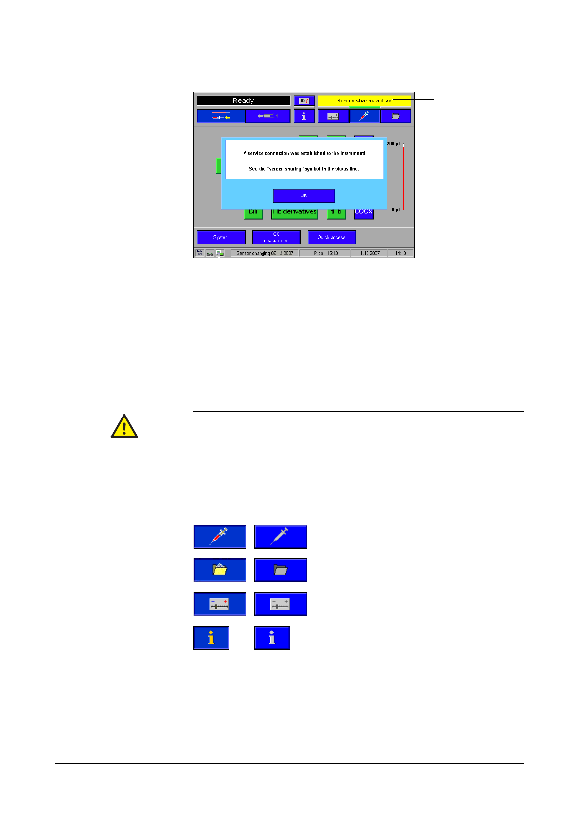
B
A
A "Screen sharing" Symbol B "Screen sharing" active
Figure A-2
Confirm the message with [OK] either on the instrument or on the PC. The "screen
sharing" symbol is added in the status line.
To avoid multiple operation of the instrument, the message "Screen sharing active" is
displayed with a yellow background in the error and message window of the
instrument.
As long as the "screen sharing" symbol is displayed in the status line, the service connection is
active. In order to prevent multiple operation of the instrument, no buttons on the screen should be
pressed!
Important buttons on the screen
Buttons Description
"Analyzer" active / inactive
"Database" active / inactive
"Setup" active / inactive
"Info" active / inactive
e
For additional information, see Chapter 9 Software modes, section Buttons on page B-76.
Roche Diagnostics April 2009
A-12 Instructions for Use · Revision 10.0
Page 25

cobas b 221 system 2 General descriptions
Measurement and calibration procedure
Measurement and calibration procedure
Measurement procedure
PO2: Use of the Clark measurement principle: measurement of current generated by
the reduction of oxygen.
PCO
: Use of the Severinghouse principle: potentiometric measurement of the pH
2
change in the electrode caused by CO
pH- , Na
+
-,K+-, Ca2+- und Cl- electrodes are potentiometric electrodes. Special
glasses are used as the sensitive element for pH and Na
membranes contain special neutral carriers. A special ion exchanger is used for
chloride membranes. Calculation of these variables also requires the use of a reference
electrode—a permanently contacted chloride electrode in the cobas b 221 system.
Glucose, lactate: Glucose oxidizes to form gluconolacton using atmospheric oxygen
and the glucose-oxidase (GOD) enzyme, lactate oxidizes to form pyruvate using the
lactate oxidase enzyme.
The generated H
is determined amperometrically by using manganese dioxide/
2O2
carbon electrode at 350 mV.
.
2
+
. The potassium and calcium
Calibration procedure
Oxygen (O
PCO
, pH, ISE: are calibrated using two solutions mixed under different conditions, thereby avoiding
2
): Ambient air and a zero point solution are used to calibrate oxygen.
2
MSS: The calibration is carried out with four (Glu, Lac) or five solutions (Urea/BUN)
Urea: Urea is broken into ammonia and carbon dioxide through urease. Ammonia
and carbon dioxide react through hydrolysis with physiological pH to form ammonia
or bicarbonate ions. The ammonia ions can be determined using a potentiometrical
ammonia ion-selective electrode. This measurement requires a reference electrode
such as those used in ion-selective electrodes.
tHb/SO
: Light absorption in whole blood is measured at four different wavelengths,
2
the sample is subjected to light radiation and the dispersed light is also evaluated.
COOX: The hemoglobin derivatives and the total bilirubin (= neonatal) are
determined spectrophotometrically based on the Lambert-Beer law.
Hematocrit: Measurement of the sample's conductivity in the ISE measuring
chamber.
tHb and SO2 was calibrated when the instrument was manufactured.
the gas supply which is required by other instruments.
whose weighing concentrations form the basis for measured value determination.
COOX: Determining the hemoglobin derivatives and the total bilirubin (= neonatal) are
carried out spectral-photometrically using a cuvette.
Roche Diagnostics April 2009
Instructions for Use · Revision 10.0 A-13
Page 26
2 General descriptions cobas b 221 system
Measurement evaluation
Measurement evaluation
The validity of the test results from the cobas b 221 system must be carefully
examined by a clinical-medical specialist who will take the patient's clinical condition
into consideration before any clinical decisions are reached based on the test results.
In order to ensure the quality of the measurement results, complete a quality control
test on 3 levels (low, normal, high) after each electrode exchange, after each exchange
of solutions and packs and after startup of the instrument.
Additionally complete a quality control test on one level between two automatic 2P
calibrations. The level have to be alternated (low, normal, high).
e
For detailed information, see Chapter 7 Quality control.
Safety instructions for specific dangers
Handling samples
While handling samples, all necessary regulations concerning hygiene must be
observed. Dangerous pathogenic agents could be present.
e
For more detailed information, see Chapter 6 Measurement
Disposal of waste water, bottles, packs, electrodes and the instrument
Dispose of waste water, bottles, packs, electrodes and the instrument according to local and/or labor
regulations (biologically contaminated—hazardous waste!).
Decontamination
The purpose of this decontamination is to minimize risk when handling items that
were in contact with biological samples.
Roche recommends following a decontamination procedure in addition to
regulations specific to the laboratory.
These decontamination procedures should be performed periodically to minimize the
risk of infections.
Always wear gloves!
e
For more detailed information about decontamination, see Chapter 10 Maintenance
Roche Diagnostics April 2009
A-14 Instructions for Use · Revision 10.0
Page 27
cobas b 221 system 2 General descriptions
Handling solutions
Handling solutions
Store the cobas b 221 system wash/calibrating solutions according to the specified
packaging requirements. The temperature of the solutions should be adapted to the
ambient temperature before use.
The shelf life of the solutions is limited.
Please read the bottle label and the packaging for the correct storage temperature and
the maximum shelf life.
DO NOT FREEZE!
If frozen, the solution's concentration may change and cause calibration errors!
Do not use damaged fluid packs (S2 and S3)! Do not mix the individual components!
e
For "Storage specifications", see Chapter 4 Specifications.
Handling electrodes
Store the electrodes according to the packaging specifications.
The shelf life of the electrodes is limited.
Please read the label and the packaging for the correct storage temperature and the
maximum shelf life.
CAUTION! Installation note for the PCO2 electrode
Insert the electrode into the measuring chamber within 5 minutes of opening the ALU-PE
packaging.
A special protective gas atmosphere designed to condition the PCO2 electrode during storage is
found inside the ALU-PE packaging.
This gas atmosphere ensures immediate potential stability during insertion of the electrode into the
measuring chamber and immediate readiness for measuring the first 2 point calibration.
If more than 5 minutes elapse after opening the ALU-PE packaging, the level of gas conditioning
could be lost and the time required for the first-time calibration could be increased.
e
For "Storage specifications", see Chapter 4 Specifications.
Roche Diagnostics April 2009
Instructions for Use · Revision 10.0 A-15
Page 28

2 General descriptions cobas b 221 system
General notes on the use of the MSS cassette
General notes on the use of the MSS cassette
For instrument versions with MSS module only!
Attention:
MSS cassette may only be brought into contact with liquids in the cobas b 221 system while
electrodes are changed!
Replace the MSS cassette within 28 days of installation!
After initial contact with liquids, the MSS cassette may no longer be removed from the instrument.
It may lead to the destruction of the enzyme sensors.
Storage:
At 2 – 8 °C, maximum of 2 weeks at room temperature.
MSS cassette removed from the measuring chamber
Once an MSS cassette is exposed to liquid, it must not be allowed to dry out under
any circumstances since this would destroy the enzymes. The enzymes are equipped
with a special protectant prior to shipping for transportation purposes. This
protectant is washed out inside the instrument during the warm-up phase and MSS
polarization.
Incompatible substances
The following substances may not be introduced into the MSS measuring chamber
under any circumstances since they would immediately destroy the MSS sensors or
severely impact their functionality.
o Deproteinizer (NaOCl)
o O
o Cleaning solution
o Na electrode conditioning solution
o Rinse additive
o Solutions containing heavy metals (Ag, Hg, Au, etc., e.g. Thiomersal)
o Cleaning solutions containing detergent (e.g. washing material or liquid
o All solutions for disinfections (e.g. high-percentage alcohol, glutaric dialdehyde,
o Solutions with pH values that deviate greatly from neutral
zero point solution
2
detergents)
cresol, etc.)
(e.g. pH value of < 6.0 and > 9.0)
The use of anticoagulants other than those approved by Roche Diagnostics
(approved: heparin salts), such as EDTA, citrate, NH4 heparin and glycolysis
inhibitor such as NaF and oxalate can lead to erroneous results.
Roche Diagnostics April 2009
A-16 Instructions for Use · Revision 10.0
Page 29

cobas b 221 system 2 General descriptions
General notes on the use of the MSS cassette
Inserting the MSS cassette
Hold the MSS cassette only at the designated handle and avoid touching the contacts.
e
For a detailed description see Chapter 10 Maintenance, section Changing the MSS cassette
(cobas b 221<5> system and cobas b 221<6> system only) on page C-32.
Roche Diagnostics April 2009
Instructions for Use · Revision 10.0 A-17
Page 30
2 General descriptions cobas b 221 system
System description
System description
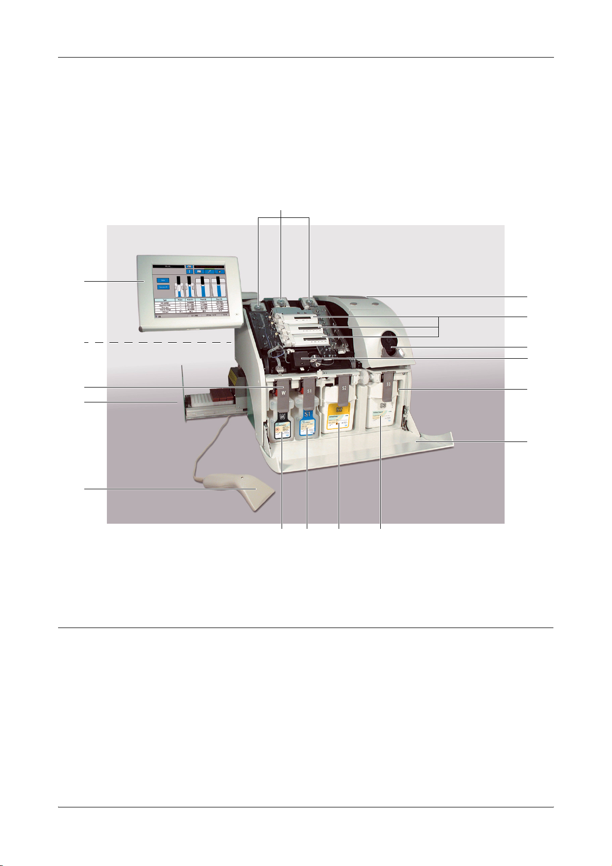
Visual identification
For example: cobas b 221<6> system
P
A
O
N
B
C
D
D
E
A Screen/PC unit
B Reverse side
C Docking mechanism
D AutoQC drawer
E Barcode scanner
F W Waste container
Figure A-3 cobas b 221<6> system
G S1 Rinse Solution
H S2 Fluid Pack
I S3 Fluid Pack
J Bottle compartement cover
K Bottle compartement
L COOX module (tHb/SO
F G H I
module)
2
M
L
K
J
M Input unit
N Measuring chambers
O Printer
P Pumps
Roche Diagnostics April 2009
A-18 Instructions for Use · Revision 10.0
Page 31

cobas b 221 system 2 General descriptions
System description
Screen/PC unit
The screen/PC unit serves as the graphical user interface.
All information (results, error messages, alarms, warnings, etc.) is displayed on the
screen. The screen consists of a color LCD that is covered with a touch-sensitive film
("touch screen").
As sharp objects can damage the touch-sensitive film, only touch the film using suitable pins and/or
with your fingers.
The screen/PC unit also contains a diskette drive.
Printer
Low-noise thermoprinter with integrated paper cutter (manually activated using the
"Cut" key) and optional winder.
The "Feed" key feeds in the paper.
Measuring chamber
tHb/SO2 module
With an installed winder, the "Automatic Cut" function is deactivated.
Underneath the top cover are the BG and, depending on the configuration, ISE
measuring chamber with the electrodes, the MSS measuring chamber with the MSS
cassette and the tHb/SO
or COOX module.
2
The electrodes are flow-through electrodes with a visible sample channel.
Figure A-4 tHb/SO2 module
The tHb/SO2 module is an optical sensor module for determining the level of total
hemoglobin (tHb) and oxygen saturation (SO
Roche Diagnostics April 2009
Instructions for Use · Revision 10.0 A-19
) in whole blood.
2
Page 32

2 General descriptions cobas b 221 system
System description
COOX module
The COOX module consists of the hemolyzer and the COOX measuring chamber.
The measurement is based on the principle of spectral photometry.
Pumps
Depending on the configuration, up to three peristaltic pumps transport the sample
and the operating fluids inside the instrument.
Input unit
The sample insertion as well as the aspiration of solutions is carried out via input unit
which consists of the following:
o T&D module:
o T&D disk
o T&D tubing set with wash-water jet
o Plug control
o Fill port
o Sample drip tray
Bottle compartment
Behind the bottle compartment cover are the S1 Rinse Solution bottle, the
S2 Fluid Pack, the W Waste Container and, depending on the configuration,
S3 Fluid Pack (cobas b 221<5> system and cobas b 221<6> system only).
Roche Diagnostics April 2009
A-20 Instructions for Use · Revision 10.0
Page 33

cobas b 221 system 2 General descriptions
System description
Reverse side
E
Power supply
A
B
A Power supply
B Main power switch and connector
C Warning and identification labels
Figure A-5 Reverse side
D Air filter
E Interfaces
This unit also contains the main power switch and the connector.
D
C
B
A
A Power supply
B Main power switch OFF
C Main power switch ON
Figure A-6 Power supply
Roche Diagnostics April 2009
Instructions for Use · Revision 10.0 A-21
C
Page 34

2 General descriptions cobas b 221 system
System description
Interfaces
Only data processing units manufactured according to the standards IEC 950
(UL1950) may be attached to the interface connections!
A B CD EF
A Power supply
B Service connector
C RS 232
Figure A-7 Interfaces (without USB)
A B C D E F
A Power supply
B Service connector
C Ext. keyboard/barcode scanner
Figure A-8 Interfaces (with USB)
D Ext. keyboard/barcode scanner
E RS 232
F 10BaseT
D RS 232
E USB
F 10BaseT
o Var ia nt 2 :
2x RS 232 interfaces (COM 1 and COM 2) (SN < 1500)
e
see Figure A-7 on page A-22
o Var ia nt 1 :
1x RS 232 interface (COM 1) and 1x USB (SN > 1500)
e
see Figure A-8 on page A-22
o 1x 10BaseT Ethernet (RJ45)
o Ext. keyboard / barcode scanner: PS/2 DIN - 6 pin female connector
o 1 service connector
o Power (power supply is connected)
No reverse compatibility from Variant 2 to Variant 1 possible.
Roche Diagnostics April 2009
A-22 Instructions for Use · Revision 10.0
Page 35

cobas b 221 system 2 General descriptions
System description
Barcode scanner
Figure A-9 Barcode scanner
o Scanning of electrode data (type, lot, expiration date)
o Scanning of patient or user identity
o Scanning of QC data (QC material, lot, basis, expiration date, target values, etc.)
o Scanning of desired alphanumeric code
Press the button on the underside to activate the scanner! A beeping sound and a brief illumination
of the LED on the upper side indicate the successful scanning of the barcode.
For more detailed information, please see enclosed manual of the PS2 hand-held scanner
(included in scope of delivery).
Roche Diagnostics April 2009
Instructions for Use · Revision 10.0 A-23
Page 36

2 General descriptions cobas b 221 system
System description
Warning and identification labels (incl. nameplate)
Figure A-10 cobas b 221<1> system, cobas b 221<3> system and cobas b 221<5> system (with tHb/SO2 module)
Figure A-11 cobas b 221<2> system, cobas b 221<4> system and cobas b 221<6> system
Roche Diagnostics April 2009
A-24 Instructions for Use · Revision 10.0
Page 37

cobas b 221 system 3 Installation and shutdown
Contents
Installation and shutdown
In this chapter, the software-guided installation and shutdown of the instrument are
described step by step. The sequence of the steps described must be strictly followed.
In this chapter
Installation .....................................................................................................................27
Location ...................................................................................................................27
Accessories ...............................................................................................................28
Installation ...............................................................................................................30
1. Screen/PC unit ............................................................................................... 30
2. Power supply ..................................................................................................31
3. Attach power cord and barcode scanner ...................................................... 31
4. Switch on ........................................................................................................31
5. Installation ..................................................................................................... 32
6. Select language ............................................................................................... 32
7. Set the date and time ..................................................................................... 32
8. Cal. intervals & timing .................................................................................. 33
9. Set valves for FMS tubing exchange ............................................................. 33
10. Fix screws at V19 (bottle compartment) .................................................... 34
11. Insert right FMS tube at VM (bottle compartment) ................................. 34
12. Insert fill port and sample inlet path (glass tube) ...................................... 35
13. Insert printer paper .....................................................................................37
14. Insert peristaltic pump tubes ......................................................................39
15. Go to AutoQC service position ..................................................................39
16. Open the AutoQC drawer and remove the AutoQC valve clamp ............. 40
17. Go to AutoQC home position .................................................................... 40
18. Open AutoQC drawer and insert ampoule holder .................................... 40
19. Open the measuring chamber cover and insert the sensors ...................... 40
20. Open bottle compartment cover and insert Waste container & packs ..... 44
21. Complete installation .................................................................................. 46
22. Perform MSS polarization (cobas b 221<5> system and
Chapter
3
Roche Diagnostics April 2009
Instructions for Use · Revision 10.0 A-25
Page 38

3 Installation and shutdown cobas b 221 system
Contents
cobas b 221<6> system only) ........................................................................... 46
23. Checking the barometer value ....................................................................47
24. Quality control ............................................................................................47
Shutdown .......................................................................................................................48
Less than 24 hours ................................................................................................... 48
Longer than 24 hours .............................................................................................. 48
1. Open bottle compartment cover and only remove bottle S1 and packs
(depending on the configuration S2 and S3). ..................................................49
2. Fill the shutdown kit with distilled water ..................................................... 49
3. Insert shutdown kit into space S2 ................................................................. 49
4. Remove shutdown kit from space S2 ............................................................ 49
5. Insert shutdown kit into space S3 (cobas b 221<5> system and
cobas b 221<6> system only) ........................................................................... 50
6. Remove shutdown kit from space S3 (cobas b 221<5> system and
cobas b 221<6> system only) ........................................................................... 50
7. Remove Waste container ............................................................................... 50
8. Open the measuring chamber cover and remove the sensors ..................... 50
9. Remove the peristaltic pump tubes .............................................................. 50
10. Remove the printer paper ...........................................................................51
11. Open T&D ................................................................................................... 52
12. Remove fill port and sample inlet path (glass tube) .................................. 52
13. Set valves for FMS tubing exchange ...........................................................53
14. Release screws at V19 (bottle compartment) ............................................. 53
15. Remove right FMS tube at VM (bottle compartment) .............................53
16. Go to AutoQC home position .................................................................... 54
17. Open the AutoQC drawer and remove the ampoule holder .....................54
18. Go to AutoQC service position ...................................................................54
19. Open AutoQC drawer and insert the AutoQC valve clamp ...................... 54
20. Go to AutoQC home position .................................................................... 55
21. Complete shutdown .................................................................................... 55
Roche Diagnostics April 2009
A-26 Instructions for Use · Revision 10.0
Page 39

cobas b 221 system 3 Installation and shutdown
Installation
Installation
Location
For best results, a suitable, level location that is not subject to direct sunlight is
required for the instrument.
When installing an instrument that was stored in a cool room or was transported at
low temperatures, be aware that condensation may have formed and could cause
disturbances to the instrument. The instrument must be climatized at room
temperature for at least one hour before beginning operation.
The following conditions must be fulfilled:
o Ambient temperature: 15 °C to 31 °C
o Ambient air pressure: 797 - 526 mmHg (106.225 - 70.13 kPa)
From approx. 3000 m above sea level or air pressure < 526 mmHg (70.13 kPa), the specifications
for parameter PO
of the clinical decisions.
After successful installation, the parameter must be permanently deactivated.
are no longer fulfilled and the parameter must no longer be used for evaluation
2
e
See section 23. Checking the barometer value on page A-47
o Avoid direct sunlight, vibration and strong electromagnetic fields (electric
motors, transformers, X-ray equipment, cellular phones...).
o A stable and level work surface (max. 1° incline with bottles installed)
o Relative humidity: 20 to 85%
o At least 10 cm free space around the instrument for air circulation and electrical
connections
o Correct voltage: 100 to 240 VAC (±10%)
After setting up the cobas b 221 system at a location that meets the necessary
conditions, the following steps must be performed to ensure the instrument is ready
for operation:
o First check the instrument and the accessories for completeness and damage. The
completeness of the delivery can be checked through comparison with the delivery
packing slip.
If anything is missing, inform the Roche representative immediately.
If the delivery has suffered damage despite careful packing, inform the transportation
company immediately. Retain the packing material and products as evidence for the
damage claim.
Handle the instrument only at the specified holding points — risk of injury!
Take care when lifting - weight of the instrument without wash/calibrating solutions and AutoQC
is approx. 45 kg!
e
See illustration on the outer packaging and in Chapter 4 Specifications, section Holding
points on page A-92!
Roche Diagnostics April 2009
Instructions for Use · Revision 10.0 A-27
Page 40

3 Installation and shutdown cobas b 221 system
Installation
Accessories
The following parts are delivered as standard equipment with the cobas b 221 system:
o 1 barcode scanner
o 2 Power cords (US and European version)
o 1 roll printer paper
o 2 pcs fill port
o 1 sample inlet path (glass tube)
o 5 system disks
o 1 RCon (reference contact)
o 1 shutdown kit
o 1 dummy electrode
o 1 dummy MSS cassette
o 2 SCon (sensor contact)
o 1 13 mm wrench (for screen/PC unit)
1 Phillips screwdriver
o 3 pump tubes
Not shown in Figure A-12 on page A-29:
o
1 screen/PC unit
o
1 power supply
o
1 fill port
o
2 system disks
Roche Diagnostics April 2009
A-28 Instructions for Use · Revision 10.0
Page 41

cobas b 221 system 3 Installation and shutdown
Installation
A
M
B
C
D
L
E
F
G
K
J
I
H
A 1 Roll printer paper
B 1 Dummy electrode
C 1 Dummy MSS cassette
D RCon (reference contact)
E SCon (sensor contact)
F 1 Sample inlet path (glass tube)
Figure A-12 Accessories
Roche Diagnostics April 2009
Instructions for Use · Revision 10.0 A-29
G 2 Power cords (US and European version)
H System disks (total of 5 pcs.)
I 1 13 mm wrench (for screen/PC unit);
1 Phillips screwdriver
J 1 Barcode scanner
K 1 Fill port
L 3 Pump tubes
M 1 Shutdown kit
Page 42

3 Installation and shutdown cobas b 221 system
Installation
Installation
1. Screen/PC unit
Ensure that the printed serial number on the rear of the screen/PC unit is the same as the unit serial
number on the nameplate!
1
Unscrew the fixing nut from the screen.
2
Place the screen/PC unit on the swivel arm.
3
At the base of the swivel arm, place the brake packet and lock nut on the shaft and
tighten using the 13 mm wrench provided in the accessories.
A
B
C
D
A Screen/PC unit
B Swivel arm
Figure A-13 Swivel arm of the Screen/PC unit
4
Connect the cable to the screen and push it into the cable routing bar.
C Fixing nut
D Brake packet
Roche Diagnostics April 2009
A-30 Instructions for Use · Revision 10.0
Page 43

cobas b 221 system 3 Installation and shutdown
Installation
2. Power supply 1
Place the power supply, including the two adapter connectors, on the holder and
position them.
A
A Screw B Holder
Figure A-14 Power supply
2
Tighten the screw.
3. Attach power cord and barcode scanner 1
Connect the power cord.
2
Connect the barcode scanner, and, if necessary, the network connection to the
appropriate port on the rear side of the cobas b 221 system.
4. Switch on
o Switch the instrument on and wait until the program has completely loaded and
started. Before starting the installation, you must set the language, in which the
unit is to be operated, the date and the time.
B
B
Roche Diagnostics April 2009
Instructions for Use · Revision 10.0 A-31
Page 44

3 Installation and shutdown cobas b 221 system
Installation
5. Installation
When carrying out the installation, follow the on-screen instructions.
Installation must be carried out completely and may not be interrupted.
Observe the listed sequence while performing the actions.
If the automatic first installation is unsuccessful, you must carry out the installation process
manually. To do this, press the following buttons:
[System] > [Utilities] > [Installation]
Processing the actions
Manual The corresponding line of the list box contains an instruction which must be
performed manually. Then press [Confirm action].
Automatic If there is an automatic sequence for any action, you can start this by clicking
[Start process].
If an action has been completed successfully (manually or automatically),
this symbol is displayed.
6. Select language
7. Set the date and time
1
Press the following buttons:
h Setup > Instrument > Language
If the current language is "English": [Instrument] > [Language]
2
Select the language.
o Press the following buttons:
h Setup > Times & Intervals > Act. time / date
Figure A-15 Act. time / date
Roche Diagnostics April 2009
A-32 Instructions for Use · Revision 10.0
Page 45

cobas b 221 system 3 Installation and shutdown
Installation
8. Cal. intervals & timing
o Press the following button:
h Setup > Times & intervals > Cal. intervals & timing
System calibration Every 8, 12 or 24 hours.
2P calibration Every 4, 8 or 12 hours.
1P calibration All 30 or 60 minutes (USA: only every 30 minutes).
9. Set valves for FMS
Figure A-16 Cal. intervals
Use this function to enter the automatic calibration times and intervals for system,
1 point and 2 point calibrations.
The time scale uses markers to show the selected interval for the 2P calibration
and the start time for the system calibration.
Intervals:
Enter the [Start time] of a system calibration to which all calibrations are oriented.
(a)
tubing exchange
o Press [Start process]. This action is performed automatically.
Valve V19 is pushed in to prevent the tube from being pinched while the aluminum part is
tightened! Valve VM is pushed out.
(a) "Fluid Mixing System" - Mixing of calibration solution A and B in a certain ratio
Roche Diagnostics April 2009
Instructions for Use · Revision 10.0 A-33
Page 46

3 Installation and shutdown cobas b 221 system
Installation
10. Fix screws at V19 (bottle compartment) 1
Open the bottle compartment cover and the docking mechanism "S3".
2
Tighten the screws on valve V19 (approx. 2-3 rotations).
e
see Figure A-17!
Use the delivered screwdriver!
A A
A Screws on valve V19
Figure A-17 Valve V19 and VM
3
To return to the installation window, close the docking mechanism and the bottle
compartment cover.
11. Insert right FMS tube at VM (bottle compartment) 1
Open the bottle compartment cover and the docking mechanism "S3".
2
Slide the tube under the tube clip of valve VM.
A B
A VM B V19
Figure A-18 Valve VM
3
Close docking mechanism and bottle compartment cover.
Roche Diagnostics April 2009
A-34 Instructions for Use · Revision 10.0
Page 47

cobas b 221 system 3 Installation and shutdown
Installation
12. Insert fill port and sample inlet path (glass tube) 1
Pull out the sample drip tray.
2
Remove the T&D cover and the unit cover.
3
Insert the fill port started from the 6 o’clock position as shown below.
4
Push the fill port straight onto the insert needle.
Do not bend the insert needle during this process!
A
A Needle
Figure A-19 Insert needle
5
Rotate the fill port 90° clockwise and upwards until it snaps into place.
Figure A-20
6
Open the T&D lock.
e
see Figure A-21 on page A-36, A
7
Insert the glass tube into the guides, fasten it and check it for a correct position.
e
see Figure A-21 on page A-36, C
e
see Figure A-21 on page A-36, D
Roche Diagnostics April 2009
Instructions for Use · Revision 10.0 A-35
Page 48

3 Installation and shutdown cobas b 221 system
A
Installation
A
A T&D lock
B Glass tube
Figure A-21 Glass tube
B
C
C Insert the glass tube into the guides
D Fasten and check for correct position
C
D
8
Close the T&D lock again. Check the correct positioning of the sample inlet path
to the bypass nipple (see below)!
A Bypass nipple
Figure A-22 T&D lock
9
Close the T&D cover.
10
Insert the sample drip tray.
Roche Diagnostics April 2009
A-36 Instructions for Use · Revision 10.0
Page 49

cobas b 221 system 3 Installation and shutdown
Installation
13. Insert printer paper
The printer paper is heat sensitive on one side only. Observe the correct insertion of the thermal
paper roll.
A
B
A Printer cover B Paper lid
Figure A-23 Printer
1
Open the printer cover and the paper lid.
2
Cut the start of the paper so that it is straight.
3
Place the paper roll into the holder.
4
Make sure that the printer lever is in the "down" position (see below).
A
A Printer lever "down" position
Figure A-24 Printer lever
Roche Diagnostics April 2009
Instructions for Use · Revision 10.0 A-37
Page 50

3 Installation and shutdown cobas b 221 system
Installation
5
Insert the beginning of the paper according to the instructions on the inside of the
paper lid (see below).
A
B
A Paper lid B Printer lever
Figure A-25 Insert printer paper - without take-up unit
Figure A-26 Insert printer paper - with take-up unit (optional)
6
The paper is automatically pulled into the printer.
7
Close paper lid.
With take-up unit (optional)
1
Press the paper feed button until the paper is long enough.
2
Insert the beginning of the paper in the take-up unit according to the instructions
on the inside of the paper lid.
e
see Figure A-26 on page A-38
Press the take-up unit (rods) fully onto the holder and rotate until the paper is taut on the rods and
paper lid, so that the entire roll of paper can be taken up. During operation, the paper should be
tautened now and then by turning the take-up roller.
3
Close printer cover.
With an installed take-up unit, the "Automatic Cut" function is deactivated.
Roche Diagnostics April 2009
A-38 Instructions for Use · Revision 10.0
Page 51

cobas b 221 system 3 Installation and shutdown
Installation
14. Insert peristaltic pump tubes 1
Open the peristaltic pump's clear plastic cover (tension lever).
2
Push the linear bracket (white plastic part) upwards (see below).
A
B
C
A Te ns i on l e ver
B Pump head
C Linear bracket
Figure A-27 Peristaltic pump
3
Place the tubing set around the corresponding rolling wheel (see below/A). Check
that the tubing set is correctly orientated (the grip end must be pointing upwards,
see below/B).
4
Close the clear plastic cover (tension lever). The tubing holder is then pressed into
the sealer (see below/B).
A Place the tubing set B Close the tension lever
Figure A-28 Peristaltic pump
AutoQC module (option)
The installation with an AutoQC module (optional) must be performed by a Roche Diagnostics
Service Representative!
15. Go to AutoQC service position
o Press [Start process]. This action is performed automatically.
Roche Diagnostics April 2009
Instructions for Use · Revision 10.0 A-39
Page 52

3 Installation and shutdown cobas b 221 system
Installation
16. Open the AutoQC drawer and remove the AutoQC valve clamp 1
Pull out the AutoQC drawer.
2
Pull the key of the AutoQC valve up and out (see below).
A
A AutoQC valve clamp
Figure A-29 AutoQC valve clamp
3
Close the AutoQC drawer.
17. Go to AutoQC home position
o Press [Start process]. This action is performed automatically.
18. Open AutoQC drawer and insert ampoule holder 1
Pull the AutoQC drawer out again.
A without ampoule holder B with ampoule holder
Figure A-30 AutoQC drawer
2
Insert the AutoQC ampoule holder.
3
Close the AutoQC drawer.
19. Open the measuring chamber cover and insert the sensors
a BG / ISE measuring chamber
1
Open the measuring chamber cover (push the right edge of the MC cover to the
left with a finger and open up the MC cover).
In each case, open only the relevant measuring chamber.
Keep the bottle compartment cover closed.
Roche Diagnostics April 2009
A-40 Instructions for Use · Revision 10.0
Page 53

cobas b 221 system 3 Installation and shutdown
Installation
The following screen appears:
Figure A-31 Changing of electrodes
2
Open the locking lever.
e
see Figure A-34 on page A-42
3
Follow the instructions on the screen.
Check the internal electrolyte of the electrodes for possible air bubbles (see below).
If there are air bubbles between the contact pin and the membrane, there will not be effective
electrical conduction. Result: calibration and measurement errors!
4
Remove any air bubbles.
Remove air bubbles by holding the electrode vertically and by tapping lightly with
a fingernail against the electrode body (see below).
A
A Free of air bubbles!
Figure A-32 Electrode
5
Insert the electrodes, beginning at the right and proceeding left according to the
color code.
6
Push all electrodes slightly to the right so that they are lined up together without
gaps.
Roche Diagnostics April 2009
Instructions for Use · Revision 10.0 A-41
Page 54

3 Installation and shutdown cobas b 221 system
Installation
a Insertion of the reference electrode
1
Insert the reference electrode.
Figure A-33 Reference electrode
2
Insert the reference tube into the upper tube guide channel of the left locking lever
and into the tube holder of the cover hinge. Close the locking lever (see below).
A
A Locking lever
Figure A-34 Insertion of the reference electrode
3
Connect the white connector on the end of the tube to the measuring chamber
cassette (see below).
A
B
A Connector B Measuring chamber cassette
Figure A-35 Insertion of the reference electrode 2
4
Scan the barcodes located on the inner packaging of each electrode or enter the
barcodes manually with the help of the keyboard.
5
Close the measuring chamber cover.
Roche Diagnostics April 2009
A-42 Instructions for Use · Revision 10.0
Page 55

cobas b 221 system 3 Installation and shutdown
Installation
a MSS measuring chamber (for instrument versions with MSS module only)
Hold the MSS cassette only at the designated handle and avoid touching the contacts.
1
Open the cover of the MSS measuring chamber (apply force to the right edge of
the MC cover with a finger to push it to the left and open up the MC cover).
Keep the bottle compartment cover closed!
2
Open the contact clip and the locking lever.
3
Depending on the MSS parameter configuration, insert the MSS reference
electrode (Ref + dummy) (see Figure A-36/A) or the reference contact (RCon)
(see Figure A-36/B) and the MSS cassette, close the contact clip and the locking
lever.
A
A Ref + dummy (for Glu/Lac/Urea) B RCon (Glu or Glu/Lac)
D
C
C Locking lever
D Contact clip
Figure A-36 MSS measuring chamber
4
Read in the barcode of the packaging.
5
Close the measuring chamber cover.
6
Close the top cover.
7
Prepare a syringe or capillary with whole blood for polarization. Having
B
completed the installation process, the unit requests a blood sample.
The blood should have a volume of at least 150 μL, contain heparin as an anticoagulant, and be
stored for less than 24 hours.
Roche Diagnostics April 2009
Instructions for Use · Revision 10.0 A-43
Page 56

3 Installation and shutdown cobas b 221 system
Installation
20. Open bottle compartment cover and insert Waste container & packs
A
A
B
A Ruber sealings Bcobasb221<5> system and
cobas b 221<6> system only
Figure A-37 Waste container & packs
1
Open the bottle compartment cover.
2
Open the corresponding docking mechanism.
3
Insert an empty waste water bottle and a S1 Rinse Solution bottle.
Remove packs’ rubber sealings.
4
Push the two packs into the appropriate location in accordance with the labeling
on the docking mechanisms until the packs lock.
Using the transponder attached to the bottle/packs, the instrument automatically
recognizes the corresponding bottle or packs.
A
Acobasb221<5> system and cobas b 221<6> system only
Figure A-38 Changing of bottles and packs
Roche Diagnostics April 2009
A-44 Instructions for Use · Revision 10.0
Page 57

cobas b 221 system 3 Installation and shutdown
Installation
A
Acobasb221<5> system and cobas b 221<6> system only
Figure A-39 Bottle compartment
5
Close the docking mechanism and the bottle compartment cover.
To avoid splashing the S1 Rinse Solution, deaerate the bottle at about 3000 m above sea level or
higher before inserting it.
6
Place the bottle tool on the screw cap of the S1 Rinse Solution (see below).
A Bottle tool B Screw cap with placed bottle tool
Figure A-40 Screw cap
7
Press the grips together and press the transparent disk downward (see below/A).
8
Rotate the transparent disk clockwise and stop when you notice a resistance after a
short distance (see below/B).
AB
Figure A-41 Open bottle
Roche Diagnostics April 2009
Instructions for Use · Revision 10.0 A-45
Page 58

3 Installation and shutdown cobas b 221 system
Installation
21. Complete installation 1
Press the [Complete installation] button.
Automatic sequences take place and the unit warms up.
2
Installation is complete.
If a power failure occurs during installation, the installation starts anew with the next restart.
Actions which were performed successfully are discarded.
22. Perform MSS polarization (cobas b 221<5> system and cobas b 221<6> system only) 1
Prepare a syringe or capillary with whole blood for polarization.
The blood should have a volume of at least 150 μL, contain heparin as an anticoagulant, and be
stored for less than 24 hours.
Figure A-42 MSS polarization
2
The blood sample is inserted via fill port similar to a measurement.
e
see Chapter 6 Measurement
3
The MSS cassette is subsequently exposed to liquid, polarized and heated.
4
A system calibration is carried out.
5
If, after inserting the cassette, the automatic polarization was not successful and
the MSS sensors are not calibrated, you must manually polarize the MSS cassette.
To do this, press the following buttons:
h System > Utilities > MSS polarization
6
Follow the instructions on the screen!
Roche Diagnostics April 2009
A-46 Instructions for Use · Revision 10.0
Page 59

cobas b 221 system 3 Installation and shutdown
Installation
23. Checking the barometer value
h System > Component test > Control sensors > Baro sensor
1
If the barometer value deviates by more than ± 4 mbar from the value indicated by
a precision barometer, it will be necessary for Technical support to calibrate the
barometer!
A wrong barometer value leads to wrong PO2 measurement results.
Important:
From approx. 3000 m above sea level or air pressure < 526 mmHg (70.13 kPa), the specifications
24. Quality control
for parameter PO
of the clinical decisions. The parameter PO2 must be permanentely deactivated.
2
To deactivate the parameter PO2 press the following buttons:
h Setup > Parameter > Miscellaneous settings > Activated / deactivated for calibrations
1
Define the material and if an AutoQC drawer (option) is available insert the mats
before performing a quality control measurement.
are no longer fulfilled and the parameter must no longer be used for evaluation
2
e
For details, see Chapter 7 Quality control
2
Perform quality control tests for all 3 levels (low, normal, high). Make sure that
the results agree with the target values.
e
See Chapter 7 Quality control
Roche Diagnostics April 2009
Instructions for Use · Revision 10.0 A-47
Page 60

3 Installation and shutdown cobas b 221 system
Shutdown
Shutdown
Less than 24 hours
If the cobas b 221 system is not used for a short period of time only (< 24 hours), then
activate the following function, starting with the top level of the analyzer mode:
h System > Utilities > Shutdown PC
This function allows for switching off the touch screen/PC unit and is completed with
manually switching off the instrument.
Follow the instructions on the screen!
MSS sensors (Glu / Lac / Urea/BUN) are destroyed during this operation.
If the instrument is turned on again, a new MSS cassette must be inserted.
e
See section 19. Open the measuring chamber cover and insert the sensors on page A-40.
Longer than 24 hours
If the cobas b 221 system will be shut down for longer than 24 hours, perform the
following procedure.
Before performing a shutdown, Roche Diagnostics recommends decontaminating all surfaces and
tube paths.
e
see Chapter 10 Maintenance, Abschnitt Decontamination on page C-5!
Activate the following function, starting with the top level of the analyzer mode:
h System > Utilities > Put out of operation
All solutions and electrodes have to be removed during the shutdown procedure.
The procedure ends in switching off the instrument.
Follow the instructions on the screen.
Observe the listed sequence while performing the actions.
Processing the actions:
Manual: The corresponding line of the list box contains an instruction which must be
performed manually. Then press [Confirm action].
Automatic: If there is an automatic sequence for any action, you can start this by clicking [Start
process].
Roche Diagnostics April 2009
A-48 Instructions for Use · Revision 10.0
Page 61

cobas b 221 system 3 Installation and shutdown
Shutdown
Upon successful completion, this symbol is displayed.
1. Open bottle compartment cover and only remove bottle S1 and packs
(depending on the configuration S2 and S3).
1
Open bottle compartment cover and docking mechanism and remove bottle S1
and the packs (S2 and S3).
Do not remove the waste container!
2
Close docking mechanism and bottle compartment cover.
2. Fill the shutdown kit with distilled water
o Fill the shutdown kit about halfway with distilled water.
Figure A-43 Shutdown kit
3. Insert shutdown kit into space S2 1
Open bottle compartment cover and docking mechanism S2 and insert the
shutdown kit into space S2.
2
Close docking mechanism and bottle compartment cover.
3
Perform "Washing of the tubes".
4. Remove shutdown kit from space S2 1
Open bottle compartment cover and docking mechanism S2 and remove the
shutdown kit.
2
Close docking mechanism and bottle compartment cover.
3
Perform "Emptying of the tubes".
Roche Diagnostics April 2009
Instructions for Use · Revision 10.0 A-49
Page 62

3 Installation and shutdown cobas b 221 system
Shutdown
5. Insert shutdown kit into space S3 (cobas b 221<5> system and cobas b 221<6> system only) 1
Open bottle compartment cover and docking mechanism S3 and insert the
shutdown kit into space S3.
2
Close docking mechanism and bottle compartment cover.
3
Perform "Washing of the tubes".
6. Remove shutdown kit from space S3 (cobas b 221<5> system and cobas b 221<6> system only) 1
Open bottle compartment cover and docking mechanism S3 and remove the
shutdown kit.
2
Close docking mechanism and bottle compartment cover.
3
Perform "Emptying of the tubes".
7. Remove Waste container 1
Open bottle compartment cover and docking mechanism W.
2
Remove the waste water container (W Waste Container).
3
Close docking mechanism and bottle compartment cover.
8. Open the measuring chamber cover and remove the sensors 1
Remove the top cover and open all measuring chamber covers.
2
Open the measuring chamber cover (push the right edge of the MC cover to the
left with a finger and open up the MC cover).
3
Open the locking levers and the contact clip (MSS measuring chamber).
4
Sequentially remove the electrodes and the MSS cassette from the measuring
chambers.
5
Close the locking lever, the contact clip and all the measuring chamber covers.
9. Remove the peristaltic pump tubes 1
Open the peristaltic pump's clear plastic cover (tension lever) (see below).
A
B
C
A Te ns i on l e ver
B Pump head
C Linear bracket
Figure A-44 Peristaltic pump
2
Push the linear bracket (white plastic part) upwards (see below/A).
Roche Diagnostics April 2009
A-50 Instructions for Use · Revision 10.0
Page 63

cobas b 221 system 3 Installation and shutdown
Shutdown
3
Remove the complete tubing set (tubing holder and tubing) of the corresponding
pump (see below/B)
A Push the linear bracket upwards B Remove the tubing set
Figure A-45 Peristaltic pump
4
Close the tension lever.
10. Remove the printer paper 1
Open the printer cover and the paper lid.
A
B
A Printer cover B Paper lid
Figure A-46 Printer cover / paper lid
2
Move the printer lever upwards (see below/A).
A Printer lever "upwards" B Printer lever "down"
Figure A-47 Printer lever
Roche Diagnostics April 2009
Instructions for Use · Revision 10.0 A-51
Page 64

3 Installation and shutdown cobas b 221 system
Shutdown
3
Remove the printer paper.
4
Move the printer lever down again (see above/B).
5
Close the paper lid and the printer cover.
11. Open T&D
o Press [Start process]. This action is performed automatically.
The T&D disk turns to position 1.
12. Remove fill port and sample inlet path (glass tube) 1
Remove the sample drip tray.
2
Remove the T&D cover.
3
Open the T&D lock and remove the sample inlet path (glass tube).
A
B
A T&D lock B Sample inlet path (glass tube)
Figure A-48 T&D lock & sample inlet path
4
Turn the fill port downward by 90° and pull it straight off of the needle.
Do not bend the needle!
Roche Diagnostics April 2009
A-52 Instructions for Use · Revision 10.0
Page 65

cobas b 221 system 3 Installation and shutdown
Shutdown
A Fill port B Needle
Figure A-49 Fill port
5
Close the T&D lock again.
6
Close the T&D cover.
13. Set valves for FMS tubing exchange
o Press [Start process]. This action is performed automatically.
Both valves are pushed out.
14. Release screws at V19 (bottle compartment) 1
Open the bottle compartment cover and the docking mechanism S3.
2
Loosen the screws (A) of the aluminum part of valve V19 (approx. 2-3 turns).
A
B
A
A
V 19
A Screws
Figure A-50 Valve V19
3
Close the docking mechanism S3 and the bottle compartment cover.
15. Remove right FMS tube at VM (bottle compartment) 1
Open the bottle compartment cover and the docking mechanism S3.
2
Slide the tube out under the tube clip of valve VM.
Roche Diagnostics April 2009
Instructions for Use · Revision 10.0 A-53
Page 66

3 Installation and shutdown cobas b 221 system
Shutdown
B
A
A VM B Tube clip
Figure A-51 Valve VM
3
Pressure is removed from the tubes.
4
Close the docking mechanism and the bottle compartment cover.
If available (option):
16. Go to AutoQC home position
o Press [Start process]. This action is performed automatically.
17. Open the AutoQC drawer and remove the ampoule holder 1
Pull out the AutoQC drawer.
2
Remove the AutoQC ampoule holder.
3
Remove the already opened ampoules from the mats and dispose of them
according to the local guidelines.
If individual ampoules remain in the white ampoule holder after removing the mats, note that
these open ampoules may break on removal with the attendant risk of injury.
Before inserting a new mat remove them all carefully!
Always wear gloves! CAUTION: Danger of spilling!
4
Leave the full ampoules in the mats and store them in a refrigerator in accordance
with their storage temperature (see packaging insert).
5
Close the AutoQC drawer.
18. Go to AutoQC service position
o Press [Start process]. This action is performed automatically.
19. Open AutoQC drawer and insert the AutoQC valve clamp 1
Pull out the AutoQC drawer.
2
Insert the clamp of the AutoQC valve (see below).
Roche Diagnostics April 2009
A-54 Instructions for Use · Revision 10.0
Page 67

cobas b 221 system 3 Installation and shutdown
Shutdown
A
A AutoQC valve clamp
Figure A-52 AutoQC valve clamp
3
Close the AutoQC drawer.
20. Go to AutoQC home position
o Press [Start process]. This action is performed automatically.
21. Complete shutdown 1
Press the [Complete shutdown] button.
Shut down is complete. The following screen appears:
Figure A-53 Shutdown
2
Press the [Shutdown PC] button. Follow the instructions on the screen.
The PC is booted down.
3
Turn off the device.
4
Close top cover.
Remove the transport, power cable, scanner and, if available, network connectors.
Roche Diagnostics April 2009
Instructions for Use · Revision 10.0 A-55
Page 68

3 Installation and shutdown cobas b 221 system
Shutdown
Roche Diagnostics April 2009
A-56 Instructions for Use · Revision 10.0
Page 69

cobas b 221 system 4 Specifications
Contents
Specifications
In this chapter, the performance data, as well as product and environmental data are
described.
In this chapter
Performance data ..........................................................................................................59
Measurement parameters ........................................................................................59
Reproducibility ........................................................................................................60
Linearity ................................................................................................................... 70
Correlation to other methods .................................................................................82
Sample throughput .......................................................................................................86
Measurement times of the samples .............................................................................. 86
Sample volumes ............................................................................................................. 87
Sample types .................................................................................................................. 87
Calibrations ...................................................................................................................88
Environmental parameters ........................................................................................... 89
Temperature / humidity / stability .........................................................................89
Product data ..................................................................................................................91
Electrical data ..........................................................................................................91
Classification ............................................................................................................91
Dimensions ..............................................................................................................91
Weight ......................................................................................................................91
Acoustic Noise Level ................................................................................................ 91
Holding points ......................................................................................................... 92
AutoQC .......................................................................................................................... 92
Printer ............................................................................................................................92
Touch screen-PC unit .................................................................................................... 93
Barcode Scanner ............................................................................................................ 93
Chapter
4
Roche Diagnostics April 2009
Instructions for Use · Revision 10.0 A-57
Page 70

4 Specifications cobas b 221 system
Contents
Roche Diagnostics April 2009
A-58 Instructions for Use · Revision 10.0
Page 71

cobas b 221 system 4 Specifications
Performance data
Performance data
Measurement parameters
Parameter specified for specified range
PO
2
PCO
2
pH B/Q/S/PF 6.0 - 8.0
Sodium B/Q/S/A/D 20 - 250 mmol/L
Potassium B/Q/S/A/D 0.2 - 20 mmol/L
Chloride B/Q/S 20 - 250 mmol/L
ionized Calcium B/Q/S/A/D 0.1 - 4.0 mmol/L 0.4008 - 16.032 mg/dL
Hct B/Q 10 – 80 %
(a)
Glucose
(cobas b 221<5> system,
cobas b 221<6> system only)
Lactate (cobas b 221<5> system,
cobas b 221<6> system only)
Urea (cobas b 221<6> system only) B/Q/S 0.5 – 30 mmol/L 3.0028 - 180.168 mg/dL
tHb module B/Q 3 – 25 g/dL 1.8606 - 15.505 mmol/L
module B/Q 50 – 100 %
SO
2
tHb (COOX) B/Q 3 – 25 g/dL
(COOX) B/Q 0 – 100 %
SO
2
HHb (COOX) B/Q 0 – 100 %
COHb (COOX) B/Q 0 – 100 %
Hb (COOX) B/Q 0 – 100 %
O
2
MetHb (COOX) B/Q 0 – 100 %
Bilirubin (neonatal) (COOX) B/Q 3 - 50 mg/dL 51.3 - 855 μmol/L
Baro 450 - 800 mmHg
Ta b l e A - 1 Measurement parameters
(a) Due to the current specifications, clinically significant deviations in the range < 3mmol/L can occur compared to other glucose measuring systems.
Especially in the neonatal field, we therefore recommend carrying out a comparative blood measurement relative to a known reference system or to
adapt the correlation table (refer to the Reference Manual, chapter "Setup" section "Correlation"). For any questions concerning this matter, contact
the local Roche organization.
B/Q 0 - 800 mmHg
B/Q 4 – 200 mmHg
B/Q/S 0.5 – 40 mmol/L 9.01 - 720.8 mg/dL
B/Q/S 0.2 – 20 mmol/L 1.8016 - 180.16 mg/dL
B
Q
A
D
S
PF
(a) with approximate physiological ion matrix and buffer capacity
Roche Diagnostics April 2009
Instructions for Use · Revision 10.0 A-59
Whole blood
Aqueous QC material
(a)
Dialysis solutions containing acetate
Dialysis solutions containing bicarbonate
Serum or plasma
Pleural fluid (can be measured in serum/plasma mode)
Page 72

4 Specifications cobas b 221 system
Performance data
Reproducibility
"Within-Run (Swr)" and "Total Precision (ST)" was determined from 2 runs per day
with 2 replicates per run for 20 days on four cobas b 221 systems.
The mean value is the measured value of the corresponding parameter for which S
and S
are representative resp. have been determined.
T
Parameter Unit
pH pH units
PCO
2
PO
2
Sodium mmol/L
Potassium mmol/L
Chloride mmol/L
ionized Calcium mmol/L
Hct %
Lactate (cobas b 221<5> system,
cobas b 221<6> system only)
Glucose (cobas b 221<5> system,
cobas b 221<6> system only)
Urea (cobas b 221<6> system only) mmol/L
tHb (tHb module) g/dL
(tHb module) %
SO
2
tHb (COOX) g/dL
(COOX) %
SO
2
Hb %
O
2
COHb %
MetHb %
HHb %
Bilirubin (neonatal) mg/dL
Ta b le A - 2 Units of the parameters
mmHg
mmHg
mmol/L
mmol/L
wr
Material: acetat - standard solution (Level 1), NIST Traceable, n=80
Parameter Mean S
wr
Sodium 140.0 0.5600 0.40 0.7405 0.53
Potassium 2.02 0.0165 0.82 0.0290 1.44
Chloride -----
ionized Calcium 1.622 0.0155 0.96 0.0205 1.26
Ta b l e A - 3 Acetat - standard solution (Level 1), NIST Traceable, n=80
Roche Diagnostics April 2009
A-60 Instructions for Use · Revision 10.0
(CV%) S
T
(CV %)
Page 73

cobas b 221 system 4 Specifications
Performance data
Material: acetat - standard solution (Level 2), NIST Traceable, n=80
Parameter Mean S
wr
(CV%) S
T
(CV %)
Sodium 140.1 0.5107 0.36 0.7747 0.55
Potassium 4.00 0.0171 0.43 0.0273 0.68
Chloride -----
ionized Calcium 1.166 0.0077 0.66 0.0141 1.21
Ta b l e A - 4 Acetat - standard solution (Level 2), NIST Traceable, n=80
Material: tonometered human whole blood, 20 different probands, n=80
Parameter Mean S
wr
pH 7.441 0.0042 0.06 - -
PCO
PO
2
2
18.3 0.3331 1.82 0.6262 3.42
137.9 0.9371 0.68 2.3258 1.69
Sodium 139.5 0.4878 0.35 - -
Potassium 4.58 0.0260 0.57 - -
Chloride 108.4 0.4310 0.40 - -
ionized Calcium 1.181 0.0079 0.67 - -
Hct 43.3 0.3203 0.74 - -
Lactate 11.5 0.1769 1.54 - -
Glucose 1.8 0.0648 3.51 - -
Urea 4.8 0.0529 1.11 - -
tHb (tHb module) 15.4 0.1461 0.95 - -
(tHb module) 96.6 0.3744 0.39 - -
SO
2
tHb (COOX) 14.1 0.0773 0.55 - -
(COOX) 99.9 0.0613 0.06 - -
SO
2
Hb 97.9 0.0684 0.07 - -
O
2
COHb 1.4 0.0377 2.79 - -
MetHb 0.7 0.0287 4.10 - -
HHb 0.1 0.0601 - - -
Ta b l e A - 5 Tonometered human whole blood, 20 different probands, n=80
(CV%) S
T
(CV %)
Roche Diagnostics April 2009
Instructions for Use · Revision 10.0 A-61
Page 74

4 Specifications cobas b 221 system
Performance data
Material: tonometered human whole blood, 20 different probands, n=80
Parameter Mean Swr (CV%) ST (CV %)
pH 7.129 0.0049 0.07 - -
PCO
2
PO
2
Sodium 142.3 0.7126 0.50 - -
Potassium 4.32 0.0392 0.91 - -
Chloride 105.2 0.5184 0.49 - -
ionized Calcium 1.301 0.0136 1.05 - -
Hct 40.4 0.2795 0.69 - -
Lactate 8.7 0.2021 2.33 - -
Glucose 2.3 0.0977 4.31 - -
Urea 4.9 0.0583 1.18 - -
tHb (tHb module) 15.9 0.1315 0.83 - -
(tHb module) 55.0 0.8839 1.61 - -
SO
2
tHb (COOX) 14.1 0.1691 1.20 - -
(COOX) 67.8 0.2479 0.37 - -
SO
2
Hb 66.9 0.3437 0.51 - -
O
2
COHb 1.6 0.0549 3.53 - -
MetHb 0.4 0.0504 12.14 - -
HHb 31.5 0.3121 0.99 - -
Ta b l e A - 6 Tonometered human whole blood, 20 different probands, n=80
79.5 1.2629 1.59 1.9644 2.47
40.1 0.3297 0.82 0.5976 1.49
Material: human plasma, n=80
Parameter Mean Swr (CV%) ST (CV %)
pH 7.670 0.0097 0.13 0.0549 0.72
PCO
2
PO
2
Sodium 140.9 0.7783 0.55 0.9920 0.70
Potassium 3.99 0.0514 1.29 0.0603 1.51
Chloride 106.0 0.4967 0.47 0.7877 0.74
ionized Calcium 1.155 0.0174 1.51 0.0339 2.94
Hct -----
Lactate 2.3 0.0349 1.52 0.1150 5.00
Glucose 5.7 0.0818 1.44 0.1695 2.97
Urea 4.8 0.0873 1.81 0.1005 2.08
Ta b l e A - 7 Human plasma, n=80
-----
-----
Roche Diagnostics April 2009
A-62 Instructions for Use · Revision 10.0
Page 75

cobas b 221 system 4 Specifications
Performance data
Material: serum, n=80
Parameter Mean Swr (CV%) ST (CV %)
pH 7.731 0.0120 0.15 0.0334 0.43
PCO
2
PO
2
Sodium 140.2 0.3226 0.23 0.6567 0.47
Potassium 4.18 0.0149 0.36 0.0330 0.79
Chloride 105.2 0.4310 0.41 0.6871 0.65
ionized Calcium 1.098 0.0092 0.84 0.0323 2.94
Hct -----
Lactate 2.3 0.0353 1.53 0.0989 4.30
Glucose 5.1 0.0737 1.45 0.1834 3.62
Urea 5.2 0.0451 0.86 0.1197 2.29
Ta b l e A - 8 Serum, n=80
Material: bicarbonate, n=80
-----
-----
Parameter Mean S
wr
(CV%) S
T
(CV %)
Sodium 137.9 0.7201 0.52 1.0185 0.74
Potassium 2.00 0.0224 1.12 0.0301 1.51
Chloride -----
ionized Calcium 1.605 0.0091 0.57 0.0167 1.04
Ta b l e A - 9 Bicarbonate, n=80
Roche Diagnostics April 2009
Instructions for Use · Revision 10.0 A-63
Page 76

4 Specifications cobas b 221 system
Performance data
Material: AUTOTROL PLUS B Level 1, n=40
Parameter Mean S
wr
(CV%) S
T
(CV %)
pH 7.182 0.0039 0.05 0.0060 0.08
PCO
PO
2
2
65.8 0.8109 1.23 1.7861 2.72
55.4 3.6232 6.53 4.5447 8.20
Sodium 121.2 0.6188 0.51 1.1226 0.93
Potassium 2.97 0.0161 0.54 0.0283 0.95
Chloride 84.2 0.4971 0.59 1.6465 1.96
ionized Calcium 1.557 0.0089 0.57 0.0153 0.98
Hct 51.8 0.9534 1.84 1.1250 2.17
Lactate 9.2 0.0821 0.89 0.4539 4.92
Glucose 5.4 0.0612 1.12 0.1299 2.38
Urea 23.5 0.3307 1.41 0.6664 2.84
tHb (tHb module) -----
(tHb module) -----
SO
2
tHb (COOX) 7.8 0.0317 0.41 0.0599 0.77
(COOX) 72.1 0.0690 0.10 0.1941 0.27
SO
2
Hb 46.8 0.0844 0.18 0.2383 0.51
O
2
COHb 23.0 0.0371 0.16 0.1043 0.45
MetHb 12.0 0.0180 0.15 0.0513 0.43
HHb 18.1 0.0294 0.16 0.0830 0.46
Bili 6.1 0.0287 0.47 0.0477 0.78
Ta b l e A - 1 0 AUTOTROL PLUS B Level 1, n=40
Material: AUTOTROL PLUS B Level 2, n=40
Parameter Mean S
wr
pH 7.411 0.0031 0.04 0.0047 0.06
PCO
PO
2
2
41.0 0.4626 1.13 0.7116 1.74
93.2 2.9752 3.19 5.0160 5.38
Sodium 139.6 0.3827 0.27 0.7718 0.55
Potassium 4.76 0.0131 0.27 0.0250 0.53
Chloride 101.0 0.3290 0.33 0.9795 0.97
ionized Calcium 1.154 0.0064 0.55 0.0138 1.20
Hct 38.6 0.2840 0.74 0.6195 1.60
Lactate 1.9 0.0135 0.70 0.0798 4.12
Glucose 2.4 0.0197 0.81 0.1172 4.83
Urea 7.3 0.0538 0.74 0.1939 2.67
tHb (tHb module) -----
(tHb module) -----
SO
2
tHb (COOX) 12.1 0.0715 0.59 0.1182 0.98
(COOX) 89.6 0.1442 0.16 0.1507 0.17
SO
2
Hb 74.3 0.2843 0.38 0.3011 0.41
O
2
Ta b l e A - 1 1 AUTOTROL PLUS B Level 2, n=40
(CV%) S
T
(CV %)
Roche Diagnostics April 2009
A-64 Instructions for Use · Revision 10.0
Page 77

cobas b 221 system 4 Specifications
Performance data
Parameter Mean S
wr
(CV%) S
T
(CV %)
COHb 11.1 0.1265 1.14 0.1306 1.18
MetHb 6.0 0.0577 0.96 0.0671 1.12
HHb 8.6 0.1001 1.17 0.1041 1.21
Bili 12.4 0.0857 0.69 0.1188 0.96
Ta b l e A - 1 1 AUTOTROL PLUS B Level 2, n=40
Material: AUTOTROL PLUS B Level 3, n=40
Parameter Mean S
wr
pH 7.571 0.0027 0.04 0.0050 0.07
PCO
PO
2
2
20.3 0.3114 1.53 0.5568 2.74
144.2 5.3745 3.73 6.5040 4.51
Sodium 158.9 0.5680 0.36 0.8495 0.53
Potassium 6.97 0.0343 0.49 0.0514 0.74
Chloride 119.0 0.4810 0.40 1.0305 0.87
ionized Calcium 0.546 0.0041 0.76 0.0078 1.43
Hct 26.9 0.4193 1.56 0.4298 1.60
Lactate 0.8 0.0103 1.29 0.0562 7.02
Glucose 21.0 0.1298 0.62 0.4006 1.91
Urea 2.1 0.0202 0.94 0.0757 3.53
tHb (tHb module) -----
(tHb module) -----
SO
2
tHb (COOX) 20.4 0.1940 0.95 0.2357 1.15
(COOX) 97.5 0.1396 0.14 0.1400 0.14
SO
2
Hb 92.5 0.3581 0.39 0.3617 0.39
O
2
COHb 3.3 0.1564 4.75 0.1565 4.75
MetHb 1.9 0.0773 4.13 0.0809 4.32
HHb 2.4 0.1244 5.23 0.1249 5.25
Bili 21.6 0.1621 0.75 0.1690 0.78
Ta b l e A - 1 2 AUTOTROL PLUS B Level 3, n=40
(CV%) S
T
(CV %)
Material: AUTOTROL PLUS B Level 4B, n=40
Parameter Mean S
wr
pH 7.418 0.0014 0.02 0.0050 0.07
PCO
PO
2
2
41.3 0.2720 0.66 0.6088 1.48
96.4 5.0118 5.20 8.9120 9.24
Sodium 140.6 0.3242 0.23 0.5710 0.41
Potassium 4.77 0.0135 0.28 0.0220 0.46
Chloride 101.6 0.3679 0.36 0.9279 0.91
ionized Calcium 1.104 0.0048 0.43 0.0092 0.83
Hct 36.7 0.3883 1.06 0.5049 1.38
Lactate 5.6 0.0304 0.54 0.1607 2.85
Ta b l e A - 1 3 AUTOTROL PLUS B Level 4B, n=40
Roche Diagnostics April 2009
Instructions for Use · Revision 10.0 A-65
(CV%) S
T
(CV %)
Page 78

4 Specifications cobas b 221 system
Performance data
Parameter Mean S
wr
(CV%) S
T
(CV %)
Glucose 1.4 0.0204 1.45 0.1026 7.26
Urea 13.1 0.2512 1.91 0.7169 5.46
tHb (tHb module) -----
(tHb module) -----
SO
2
tHb (COOX) 6.4 0.0265 0.41 0.1241 1.93
(COOX) 62.7 0.2002 0.32 0.2514 0.40
SO
2
Hb 36.5 0.1973 0.54 0.2474 0.68
O
2
COHb 27.6 0.0869 0.32 0.1091 0.40
MetHb 14.2 0.0414 0.29 0.0518 0.36
HHb 21.7 0.0690 0.32 0.0866 0.40
Bili 4.2 0.0146 0.34 0.0707 1.67
Ta b l e A - 1 3 AUTOTROL PLUS B Level 4B, n=40
Material: AUTOTROL PLUS B Level 5B, n=40
Parameter Mean S
wr
pH 7.412 0.0033 0.04 0.0061 0.08
PCO
PO
2
2
41.4 0.3787 0.91 0.7924 1.91
94.7 3.1077 3.28 3.2578 3.44
Sodium 139.4 0.7465 0.54 0.8404 0.60
Potassium 4.76 0.0365 0.77 0.0339 0.71
Chloride 102.1 0.7601 0.74 1.3617 1.33
ionized Calcium 1.119 0.0062 0.56 0.0103 0.92
Hct 38.0 1.4404 3.79 1.4027 3.69
Lactate 12.9 0.1628 1.26 0.5348 4.14
Glucose 25.4 0.1913 0.75 0.5098 2.00
Urea 26.4 0.4122 1.56 2.5774 9.75
tHb (tHb module) -----
(tHb module) -----
SO
2
tHb (COOX) 23.0 0.2175 0.94 0.3139 1.36
(COOX) 98.1 0.1568 0.16 0.1744 0.18
SO
2
Hb 94.2 0.4087 0.43 0.4554 0.48
O
2
COHb 2.5 0.0852 3.37 0.1053 4.16
MetHb 1.4 0.0397 2.77 0.0519 3.62
HHb 1.8 0.0675 3.83 0.0837 4.75
Bili 24.1 0.2629 1.09 0.2728 1.13
Ta b l e A - 1 4 AUTOTROL PLUS B Level 5B, n=40
(CV%) S
T
(CV %)
Roche Diagnostics April 2009
A-66 Instructions for Use · Revision 10.0
Page 79

cobas b 221 system 4 Specifications
Performance data
Material: AUTOTROL TS+ Level 1, n=40
Parameter Mean S
wr
(CV%) S
T
(CV %)
pH 7.172 0.0037 0.05 0.0054 0.08
62.3 0.8276 1.33 1.5073 2.42
PCO
2
PO
2
50.6 4.2084 8.32 5.4278 10.74
Sodium 121.9 0.8432 0.69 1.0952 0.90
Potassium 2.98 0.0333 1.12 0.0352 1.18
Chloride 84.8 0.5243 0.62 0.9029 1.06
ionized Calcium 1.591 0.0170 1.07 0.0217 1.36
Hct 56.8 1.5547 2.74 1.5912 2.80
Lactate 9.3 0.0710 0.76 0.4680 5.01
Glucose 5.5 0.0564 1.02 0.1729 3.13
tHb (tHb module) 18.7 0.0256 0.14 0.0440 0.24
(tHb module) 100.0 0.0112 0.01 0.0112 0.01
SO
2
Ta b l e A - 1 5 AUTOTROL TS+ Level 1, n=40
Material: AUTOTROL TS+ Level 2, n=40
Parameter Mean S
wr
pH 7.406 0.0022 0.03 0.0043 0.06
43.1 0.3800 0.88 0.5716 1.33
PCO
2
PO
2
92.5 2.8967 3.13 3.5631 3.85
Sodium 136.9 0.5024 0.37 0.7705 0.56
Potassium 4.70 0.0303 0.64 0.0414 0.88
Chloride 99.4 0.3950 0.40 0.5617 0.56
ionized Calcium 1.146 0.0141 1.23 0.0178 1.56
Hct 41.6 0.3827 0.92 0.7501 1.80
Lactate 1.9 0.0163 0.86 0.0672 3.53
Glucose 2.5 0.0204 0.83 0.1044 4.23
tHb (tHb module) 14.3 0.0773 0.54 0.0794 0.56
(tHb module) 93.3 0.1776 0.19 0.1855 0.20
SO
2
Ta b l e A - 1 6 AUTOTROL TS+ Level 2, n=40
(CV%) S
T
(CV %)
Material: AUTOTROL TS+ Level 3, n=40
Parameter Mean S
wr
pH 7.567 0.0023 0.03 0.0047 0.06
22.9 0.2652 1.16 0.4763 2.08
PCO
2
PO
2
141.8 3.4549 2.44 4.0597 2.86
Sodium 156.3 0.8170 0.52 1.0626 0.68
Potassium 7.03 0.0510 0.72 0.0628 0.89
Chloride 120.3 0.4829 0.40 0.6012 0.50
ionized Calcium 0.599 0.0100 1.67 0.0128 2.13
Ta b l e A - 17 AUTOTROL TS+ Level 3, n=40
Roche Diagnostics April 2009
Instructions for Use · Revision 10.0 A-67
(CV%) S
T
(CV %)
Page 80

4 Specifications cobas b 221 system
Performance data
Parameter Mean S
wr
(CV%) S
T
(CV %)
Hct 22.9 0.5431 2.37 0.5799 2.53
Lactate 0.8 0.0316 4.02 0.0446 5.68
Glucose 21.3 0.6006 2.82 0.7883 3.70
tHb (tHb module) 8.3 0.0122 0.15 0.0319 0.39
(tHb module) 93.3 0.0355 0.04 0.0450 0.05
SO
2
Ta b l e A - 17 AUTOTROL TS+ Level 3, n=40
Material: AUTOTROL TS+ Level 4A, n=40
Parameter Mean S
wr
pH 6.880 0.0054 0.08 0.0076 0.11
87.5 1.3229 1.51 2.4825 2.84
PCO
2
PO
2
22.7 3.6828 16.23 5.1660 22.77
Sodium 88.0 0.5162 0.59 0.8391 0.95
Potassium 8.94 0.0584 0.65 0.1029 1.15
Chloride 67.8 0.5941 0.88 1.3054 1.93
ionized Calcium 2.543 0.0272 1.07 0.0452 1.78
Hct 75.8 0.8202 1.08 1.0158 1.34
Lactate -----
Glucose -----
Urea -----
tHb (tHb module) 11.0 0.0206 0.19 0.0281 0.26
(tHb module) 88.2 0.0303 0.03 0.0450 0.05
SO
2
Ta b l e A - 1 8 AUTOTROL TS+ Level 4A, n=40
(CV%) S
T
(CV %)
Material: AUTOTROL TS+ Level 5A, n=40
Parameter Mean S
wr
pH 7.730 0.0042 0.05 0.0061 0.08
9.2 1.3769 15.03 1.4213 15.51
PCO
2
PO
2
253.6 6.0686 2.39 8.7795 3.46
Sodium 174.5 0.8890 0.51 1.2891 0.74
Potassium 2.00 0.0250 1.25 0.0346 1.73
Chloride 130.3 0.7821 0.60 1.1922 0.91
ionized Calcium 0.403 0.0065 1.61 0.0109 2.70
Hct 22.0 0.6997 3.18 0.7713 3.50
Lactate -----
Glucose -----
Urea -----
tHb (tHb module) 15.8 0.0196 0.12 0.0316 0.20
(tHb module) 95.8 0.0469 0.05 0.0596 0.06
SO
2
Ta b l e A - 1 9 AUTOTROL TS+ Level 5A, n=40
(CV%) S
T
(CV %)
Roche Diagnostics April 2009
A-68 Instructions for Use · Revision 10.0
Page 81

cobas b 221 system 4 Specifications
Performance data
Material: MSS Level 1, NIST Traceable, n=80
Parameter Mean S
wr
(CV%) S
T
(CV %)
Lactate 9.4 0.0670 0.71 0.2626 2.78
Glucose 5.7 0.0337 0.60 0.1231 2.18
Urea 4.9 0.0391 0.80 0.1837 3.74
Ta b l e A - 2 0 MSS Level 1, NIST Traceable, n=80
Material: MSS Level 2, NIST Traceable, n=80
Parameter Mean S
wr
Lactate 1.9 0.0188 0.96 0.0497 2.55
Glucose 2.6 0.0267 1.05 0.0972 3.81
Urea 14.5 0.2263 1.56 0.4100 2.83
Ta b l e A - 2 1 MSS Level 2, NIST Traceable, n=80
(CV%) S
T
(CV %)
Material: human whole blood incl. bilirubin Level 1, n=40
Parameter Mean S
wr
Bili 8.2 0.1202 1.47 0.6198 7.56
Ta b l e A - 2 2 Human whole blood incl. bilirubin Level 1, n=40
(CV%) S
T
(CV %)
Material: human whole blood incl. bilirubin Level 2, n=40
Parameter Mean S
wr
(CV%) S
T
(CV %)
Bili 24.1 0.1171 0.49 0.9663 4.01
Ta b l e A - 2 3 Human whole blood incl. bilirubin Level 2, n=40
Material: human whole blood incl. bilirubin Level 3, n=40
Parameter Mean S
wr
Bili 44.0 0.1623 0.37 2.1509 4.89
Ta b l e A - 2 4 Human whole blood incl. bilirubin Level 3, n=40
(CV%) S
T
(CV %)
Roche Diagnostics April 2009
Instructions for Use · Revision 10.0 A-69
Page 82

4 Specifications cobas b 221 system
Performance data
Linearity
Tonometered whole blood Whole blood was tonometered at 37 °C to various level of gravimetrically prepared
gases with CO
manufacturer. Expected and observed values for PCO
760 mmHg.
Aqueous Solutions Expected values for the aqueous solutions are based on weighted samples.
NIST standards NIST standards are precise serums with accredited target values.
Hematocrit Measurement results of the hemofuge, which is representing the Golden Standard for
hematocrit measurements, are used as expected values for hematocrit results.
and O2 concentrations certified to ± 0.03% absolute by the
2
and PO2 were corrected to
2
Human whole blood incl.
Parameter: PO
bilirubin
(mmHg)
2
Expected bilirubin values for human whole blood incl. bilirubin are based on
weighted samples.
Material: tonometered whole blood
Number of instruments: 4 cobas b 221 systems
Measurements per measuring point and instrument: 5
Expected value Mean Swr Recovery
55.39 55.66 0.4860 100.5
83.83 83.45 0.4982 99.5
103.55 103.16 0.9034 99.6
216.97 218.54 1.9437 100.7
Ta b le A - 25 Parameter PO2 (mmHg)
Correlation
Slope 0.9904 - 1.0097
Intercept ± 0.857
Correlation coefficient 0.9998
Roche Diagnostics April 2009
A-70 Instructions for Use · Revision 10.0
Page 83

cobas b 221 system 4 Specifications
Performance data
Parameter: PCO2 (mmHg)
Material: Tonometered whole blood
Number of instruments: 4 cobas b 221 systems
Measurements per measuring point and instrument: 5
Expected value Mean Swr Recovery
14.90 13.78 0.1141 92.5
39.74 37.78 0.3911 95.1
119.43 117.09 1.3505 98.0
Ta b le A - 26 Parameter PCO2 (mmHg)
Correlation
Slope 0.9898 - 1.0103
Intercept ± 1.225
Correlation coefficient 0.9999
Parameter: pH (pH units)
Material: Tonometered whole blood
Number of instruments: 4 cobas b 221 systems
Measurements per level and instrument: 5
Expected value Mean Swr Recovery
7.52 7.52 0.0050 100
7.32 7.32 0.0042 100
6.98 6.99 0.0066 100.1
Ta b le A - 27 Parameter pH (pH units)
Correlation
Slope 0.9825 - 1.0178
Intercept ± 0.133
Correlation coefficient 0.9998
Roche Diagnostics April 2009
Instructions for Use · Revision 10.0 A-71
Page 84

4 Specifications cobas b 221 system
Performance data
Parameter: Hct (%)
Material: human whole blood, traceable to golden standard (micro centrifuge)
Number of instruments: 4 cobas b 221 systems
Measurements per level and instrument: 5
Expected value Mean Swr Recovery
11.00 11.72 0.4146 106.5
24.00 23.60 0.1804 98.3
36.00 36.51 1.0171 101.4
48.00 49.73 1.0046 103.6
68.00 68.16 0.2210 100.2
78.00 77.80 0.3925 99.7
Ta b le A - 28 Parameter Hct (%)
Correlation
Slope 0.997 - 1.003
Intercept ± 0.620
Correlation coefficient 0.999
Parameter: sodium (mmol/L)
Material: aqueous solution, NIST traceable
Number of instruments: 4 cobas b 221 systems
Measurements per level and instrument: 15
Expected value Mean Swr Recovery
19.85 21.25 0.4979 107.1
91.52 92.44 0.3018 101.0
153.49 154.83 0.3808 100.9
205.66 208.30 0.5619 101.3
258.42 262.68 1.6465 101.6
Ta b le A - 29 Parameter Sodium (mmol/L)
Correlation
Slope 0.988 - 1.012
Intercept ± 0.365
Correlation coefficient 0.9999
Roche Diagnostics April 2009
A-72 Instructions for Use · Revision 10.0
Page 85

cobas b 221 system 4 Specifications
Performance data
Parameter: potassium (mmol/L)
Material: aqueous solution, NIST traceable
Number of instruments: 4 cobas b 221 systems
Measurements per level and instrument: 15
Expected value Mean Swr Recovery
0.23 0.26 0.0159 115.0
3.12 3.12 0.0114 100.0
5.11 5.13 0.0144 100.4
9.96 10.16 0.0378 102.0
14.71 15.19 0.0624 103.3
19.36 20.15 0.0757 104.1
Ta b le A - 30 Parameter Potassium (mmol/L)
Correlation
Slope 0.960 - 1.042
Intercept ± 0.109
Correlation coefficient 0.9999
Parameter: ionized Calcium (mmol/L)
Material: aqueous solution, NIST traceable
Number of instruments: 4 cobas b 221 systems
Measurements per level and instrument: 15
Expected value Mean Swr Recovery
0.10 0.09 0.0042 92.0
0.80 0.76 0.0067 94.7
1.25 1.19 0.0055 95.2
2.50 2.39 0.0122 95.7
4.00 3.86 0.0225 96.5
6.00 5.84 0.0347 97.4
Ta b le A - 31 Parameter ionized Calcium (mmol/L)
Correlation
Slope 0.975 - 1.026
Intercept ± 0.024
Correlation coefficient 0.9999
Roche Diagnostics April 2009
Instructions for Use · Revision 10.0 A-73
Page 86

4 Specifications cobas b 221 system
Performance data
Parameter: chloride (mmol/L)
Material: aqueous solution, NIST traceable
Number of instruments: 4 cobas b 221 systems
Measurements per level and instrument: 15
Expected value Mean Swr Recovery
24.86 25.84 0.5081 103.9
93.20 93.08 0.2241 99.9
149.34 146.85 0.3541 98.3
194.98 190.16 0.6110 97.5
239.86 232.04 1.0721 96.7
Ta b le A - 32 Parameter Chloride (mmol/L)
Correlation
Slope 0.959 - 1.043
Intercept ± 2.908
Correlation coefficient 0.9999
Parameter: pH (pH units)
Material: aqueous solution, NIST traceable
Number of instruments: 4 cobas b 221 systems
Measurements per level and instrument: 15
Expected value Mean Swr Recovery
6.20 6.24 0.0022 100.7
6.87 6.89 0.0024 100.2
7.38 7.38 0.0023 100.1
7.70 7.67 0.0023 99.7
8.00 7.97 0.0035 99.7
Ta b le A - 33 Parameter pH (pH units)
Correlation
Slope 0.960 - 1.042
Intercept ± 0.293
Correlation coefficient 1.0000
Roche Diagnostics April 2009
A-74 Instructions for Use · Revision 10.0
Page 87

cobas b 221 system 4 Specifications
Performance data
Parameter: CO2 (mmHg)
Material: tonometered aqueous solution
Number of instruments: 4 cobas b 221 systems
Measurements per level and instrument: 15
Expected value Mean Swr Recovery
10.00 11.36 0.1389 113.6
20.00 20.59 0.1962 103.0
60.00 57.57 0.6557 95.9
120.00 114.24 1.5521 95.2
180.00 175.37 2.4358 97.4
Ta b le A - 34 Parameter: CO2 (mmHg)
Correlation
Slope 0.961 - 1.041
Intercept ± 0.865
Correlation coefficient 0.9994
Parameter: O
(mmHg)
2
Material: tonometerd aqueous solution
Number of instruments: 4 cobas b 221 systems
Measurements per level and instrument: 15
Expected value Mean Swr Recovery
600.00 550.24 8.2594 91.7
300.00 278.07 3.7131 92.7
140.00 140.25 0.5353 100.2
60.00 60.29 0.2923 100.5
10.00 11.71 0.4329 117.1
Ta b le A - 35 Parameter O2 (mmHg)
Correlation
Slope 0.908 - 1.101
Intercept ± 6.609
Correlation coefficient 0.9995
Roche Diagnostics April 2009
Instructions for Use · Revision 10.0 A-75
Page 88

4 Specifications cobas b 221 system
Performance data
Parameter: glucose (mmol/L)
Material: aqueous solution, NIST traceable
Number of instruments: 4 cobas b 221 systems
Measurements per level and instrument: 15
Expected value Mean Swr Recovery
0.80 0.80 0.0309 100.5
10.00 10.91 0.1274 109.1
20.00 20.21 0.3101 101.0
30.00 29.97 0.4377 99.9
40.00 38.12 0.8833 95.3
Ta b le A - 36 Parameter Glucose (mmol/L)
Correlation
Slope 0.919 - 1.088
Intercept ± 1.773
Correlation coefficient 0.998
Parameter: lactate (mmol/L)
Material: aqueous solution, NIST traceable
Number of instruments: 4 cobas b 221 systems
Measurements per level and instrument: 15
Expected value Mean Swr Recovery
0.50 0.45 0.0064 89.8
5.00 5.00 0.0420 99.9
10.00 10.11 0.0873 101.1
15.00 14.84 0.0920 98.9
20.00 19.07 0.2818 95.3
Ta b le A - 37 Parameter Lactate (mmol/L)
Correlation
Slope 0.961 - 1.041
Intercept ± 0.191
Correlation coefficient 0.9989
Roche Diagnostics April 2009
A-76 Instructions for Use · Revision 10.0
Page 89

cobas b 221 system 4 Specifications
Performance data
Parameter: urea (mmol/L)
Material: aqueous solution, NIST traceable
Number of instruments: 4 cobas b 221 systems
Measurements per level and instrument: 15
Expected value Mean Swr Recovery
0.6 0.83 0.0145 138.8
7.50 7.58 0.0921 101.0
15.00 14.84 0.2328 98.9
22.50 22.13 0.3211 98.4
30.00 29.62 0.5094 98.7
Ta b le A - 38 Parameter Urea (mmol/L)
Correlation
Slope 0.979 - 1.021
Intercept ± 0.198
Correlation coefficient 0.9991
Parameter: glucose (mmol/L)
Material: NIST 965
Number of instruments: 4 cobas b 221 systems
Measurements per level and instrument: 15
Expected value Mean Swr Recovery
5.68 5.56 0.1221 97.9
11.10 11.01 0.2250 99.2
16.36 16.69 0.3826 102.1
Ta b le A - 39 Parameter Glucose (mmol/L)
Correlation
Slope 0.9591 - 1.0426
Intercept ± 0.4273
Correlation coefficient 0.9991
Roche Diagnostics April 2009
Instructions for Use · Revision 10.0 A-77
Page 90

4 Specifications cobas b 221 system
Performance data
Parameter: sodium (mmol/L)
Material: NIST 956a
Number of instruments: 4 cobas b 221 systems
Measurements per level and instrument: 15
Expected value Mean Swr Recovery
121.40 122.04 0.4136 100.5
141.00 141.37 0.2483 100.3
160.90 160.29 0.3127 99.6
Ta b le A - 40 Parameter Sodium (mmol/L)
Correlation
Slope 0.9719 - 1.0289
Intercept ± 4.0475
Correlation coefficient 0.9999
Parameter: potassium (mmol/L)
Material: NIST 956a
Number of instruments: 4 cobas b 221 systems
Measurements per level and instrument: 15
Expected value Mean Swr Recovery
6.01 6.04 0.0202 100.6
3.99 4.00 0.0103 100.3
2.03 1.91 0.0209 94.1
Ta b le A - 41 Parameter Potassium (mmol/L)
Correlation
Slope 0.9629 - 1.0385
Intercept ± 0.1788
Correlation coefficient 0.9999
Roche Diagnostics April 2009
A-78 Instructions for Use · Revision 10.0
Page 91

cobas b 221 system 4 Specifications
Performance data
Parameter: sodium (mmol/L)
Material: NIST 909b
Number of instruments: 4 cobas b 221 systems
Measurements per level and instrument: 15
Expected value Mean Swr Recovery
120.76 119.96 0.3662 99.3
141.00 144.31 0.4298 102.3
Ta b le A - 42 Parameter Sodium (mmol/L)
Correlation
Slope 0.8311 - 1.2032
Intercept ± 25.3383
Correlation coefficient 0.9997
Parameter: potassium (mmol/L)
Parameter: chloride (mmol/L)
Material: NIST 909b
Number of instruments: 4 cobas b 221 systems
Measurements per level and instrument: 15
Expected value Mean Swr Recovery
3.42 3.29 0.0162 96.1
6.28 6.56 0.0273 104.4
Ta b le A - 43 Parameter Potassium (mmol/L)
Correlation
Slope 0.8738 - 1.1444
Intercept ± 0.6284
Correlation coefficient 1.0000
Material: NIST 909b
Number of instruments: 4 cobas b 221 systems
Measurements per level and instrument: 15
Expected value Mean Swr Recovery
89.11 88.59 0.6674 99.4
119.43 115.96 0.9763 97.1
Ta b le A - 44 Parameter Chloride (mmol/L)
Correlation
Slope 0.9032 - 1.1072
Intercept ± 8.1053
Correlation coefficient 0.9990
Roche Diagnostics April 2009
Instructions for Use · Revision 10.0 A-79
Page 92

4 Specifications cobas b 221 system
Performance data
Parameter: glucose (mmol/L)
Material: NIST 909b
Number of instruments: 4 cobas b 221 systems
Measurements per level and instrument: 15
Expected value Mean Swr Recovery
5.40 5.06 0.0294 93.7
15.00 12.17 0.1239 81.1
Ta b le A - 45 Parameter Glucose (mmol/L)
Correlation
Slope 0.7429 - 1.3461
Intercept ± 1.0482
Correlation coefficient 0.9997
Parameter: urea (mmol/L)
Material: NIST 909b
Number of instruments: 4 cobas b 221 systems
Measurements per level and instrument: 15
Expected value Mean Swr Recovery
5.51 5.40 0.0248 98.0
Ta b le A - 46 Parameter Urea (mmol/L)
Parameter: tHb (g/dL), SO
(%)
2
Material: Tonometered whole blood
Number of instruments: 4 cobas b 221<5> systems
Parameter Slope intercept Coefficient Range n
tHb 0.9892 - 1.0109 ± 0.0833 0.9904 6-18 [g/dl] 250
SO
2
Ta b l e A - 47 Parameter tHb (g/dL), SO2 (%)
0.99999 - 1.00001 ± 0.856 0.9874 51.7-100 [%] 382
Roche Diagnostics April 2009
A-80 Instructions for Use · Revision 10.0
Page 93

cobas b 221 system 4 Specifications
Performance data
Parameter: bilirubin (mg/dL)
Material: human whole blood incl. bilirubin
Number of instruments: 2 cobas b 221 systems
Measurements per level and instrument: 3
Expected value Mean Swr Recovery
6.00 6.86 0.0928 114.33
14.00 14.55 0.1417 103.93
28.00 26.28 0.1901 93.86
44.00 41.52 0.0920 94.36
Ta b le A - 48 Parameter Bilirubin (mg/dL)
Correlation
Slope 0.9038 - 1.1064
Intercept ± 1.514
Correlation coefficient 0.9996
Roche Diagnostics April 2009
Instructions for Use · Revision 10.0 A-81
Page 94

4 Specifications cobas b 221 system
Performance data
Correlation to other methods
pH
Comparison instrument Slope and intercept Bias Corr. coeff. [r] No. of samples
OMNI 6 Y = -0.063 + 1.009*X +0.007 0.990 134
Radiometer 725 Y = 0.496 + 0.933*X +0.003 0.990 99
pH meter
Ta b l e A - 4 9 pH
(a) pleural fluid - pH measuring instrument, temperature-corrected
PO
Comparison instrument Slope and intercept Bias Corr. coeff. [r] No. of samples
(a)
2
OMNI 6 Y = -0.643 + 1.031*X +1.6 % 0.987 136
Radiometer 725 Y = 4.433 + 1.013*X +6.6 % 0.996 137
Ta b l e A - 5 0 PO2
Y = 0.9963*X 0 0.999 20
Unit: [mmHg]
PCO
2
Unit: [mmHg]
Comparison instrument Slope and intercept Bias Corr. coeff. [r] No. of samples
cobas b 121 System Y = -1.452 + 1.038*X +0.4 % 0.988 129
Radiometer 55 Y = -0.301 + 1.000*X -1.2 % 0.992 144
Ta b l e A - 5 1 PCO2
tHb (cobas b 221 system with tHb/SO
module)
2
Unit: [g/dL]
Comparison instrument Slope and intercept Bias Corr. coeff. [r] No. of samples
Radiometer 725 Y = -0.581 + 1.083*X +2.0 % 0.814 96
Ta b l e A - 5 2 tHb
SO
(cobas b 221 system with tHb/SO2 module)
2
Unit: [%]
Comparison instrument Slope and intercept Bias Corr. coeff. [r] No. of samples
cobas b 121 System Y = 10.066+ 0.903*X +1.1 % abs. 0.991 130
Radiometer 715 Y = -3.969 + 1.037*X - 0.4 % 0.904 102
Ta b l e A - 5 3 SO2
Roche Diagnostics April 2009
A-82 Instructions for Use · Revision 10.0
Page 95

cobas b 221 system 4 Specifications
Performance data
tHb (cobas b 221 system with COOX module)
Unit: [g/dL]
Comparison instrument Slope and intercept Bias Corr. coeff. [r] No. of samples
OMNI 9 Y = -0.100+ 1.000*X -1.0 % 0.980 135
Radiometer 700 Y = 0.200 + 1.000*X +1.1 % 0.977 125
Ta b l e A - 5 4 tHb
Hb (cobas b 221 system with COOX module)
O
2
Unit: [%]
Comparison instrument Slope and intercept Bias Corr. coeff. [r] No. of samples
OMNI 6 Y = 2.394+ 0.971*X -0.3 % abs. 0.986 132
Radiometer 725 Y = 14.492 + 0.846*X +0.1 % abs. 0.986 132
Ta b l e A - 5 5 O2Hb
HHb (cobas b 221 system with COOX module)
Unit: [%]
Comparison instrument Slope and intercept Bias Corr. coeff. [r] No. of samples
OMNI 6 Y = -0.069+ 0.987*X -0.1 % abs. 0.986 132
Radiometer 725 Y = 0.316 + 0.816*X -0.5 % abs. 0.980 132
Ta b l e A - 5 6 HHb
MetHb (cobas b 221 system with COOX module)
Unit: [%]
For values less than 1.3%:
Comparison instrument Deviation of mean values No. of samples
OMNI 9 -0.3 % abs. 129
Radiometer 725 +0.2 % abs. 131
Ta b le A - 57 MetHb
COHb (cobas b 221 system with COOX module)
Unit: [%]
For values less than 3.5%:
Comparison instrument Deviation of mean values No. of samples
OMNI 9 +0.7 % abs. 130
Radiometer 725 +0.1 % abs. 132
Ta b le A - 58 COHb
Roche Diagnostics April 2009
Instructions for Use · Revision 10.0 A-83
Page 96

4 Specifications cobas b 221 system
Performance data
SO2 (cobas b 221 system with COOX module)
Unit: [%]
Comparison instrument Slope and intercept Bias Corr. coeff. [r] No. of samples
OMNI 6 Y = 0.100+ 1.000*X +0.1 % abs. 0.967 132
Radiometer 725 Y = 17.341 + 0.824*X +0.5 % abs. 0.988 132
Ta b l e A - 5 9 SO
2
Bilirubin (cobas b 221 system with COOX module)
Unit: [mg/dL]
Comparison instrument Slope and intercept Bias Corr. coeff. [r] No. of samples
Hitachi TBil Y = -0.127+ 0.968*X +3.7 % abs. 0.986 85
Beckman LX 20 tBil Y = -0.537 + 1.060*X +1.4 % abs. 0.980 76
Kodak Vitros tBil Y = -0.119 + 0.988*X -2.4 % abs. 0.984 73
Radiometer Y = -0.327 + 1.044 *X +10.5 % abs. 0.974 82
Ta b l e A - 6 0 Bilirubin
Hct
Unit: [%]
Comparison instrument Slope and intercept Bias Corr. coeff. [r] No. of samples
OMNI 9 Y = -0.182+ 1.003*X -0.4 % abs. 0.918 137
cobas b 121 System Y = -0.689+ 1.040*X +0.6 % abs. 0.946 141
Ta b l e A - 6 1 Hct
Sodium
Unit: [mmol/L]
Comparison instrument Slope and intercept Bias Corr. coeff. [r] No. of samples
OMNI 9 Y = -13.193+ 1.106*X +0.9 % 0.948 108
Radiometer 715 Y = -2.143 + 1.028*X +1.4 % 0.972 107
Ta b l e A - 6 2 Sodium
Potassium
Unit: [mmol/L]
Comparison instrument Slope and intercept Bias Corr. coeff. [r] No. of samples
OMNI 6 Y = -0.126+ 1.020*X -1.4 % 0.986 131
Radiometer 725 Y = -0.323 + 1.083*X +0.6 % 0.989 98
Ta b l e A - 6 3 Potassium
Roche Diagnostics April 2009
A-84 Instructions for Use · Revision 10.0
Page 97

cobas b 221 system 4 Specifications
Performance data
Calcium
Unit: [mmol/L]
Comparison instrument Slope and intercept Bias Corr. coeff. [r] No. of samples
OMNI 9 Y = -0.039+ 1.024*X -0.8 % 0.941 108
cobas b 121 System Y = -0.036+ 1.042*X +1.3 % 0.962 140
Radiometer 725 Y = -0.096 + 1.073*X -1.1 % 0.981 98
Ta b l e A - 6 4 Calcium
Chloride
Unit: [mmol/L]
Comparison instrument Slope and intercept Bias Corr. coeff. [r] No. of samples
cobas b 121 System Y = -12.459+ 1.118*X -0.7 % 0.960 139
Radiometer 725 Y = 17.100 + 0.800*X -4.0 % 0.965 98
Ta b l e A - 6 5 Chloride
Glucose
Unit: [mmol/L]
Comparison instrument Slope and intercept Bias Corr. coeff. [r] No. of samples
OMNI 9 Y = -0.461+ 1.034*X -3.9 % 0.938 134
Radiometer 715 Y = -0.867 + 1.201*X +5.2 % 0.986 107
Hitachi (Plasma) Y = -1.207+ 1.127*X -4.9 % 0.990 60
Cobas Mira (Plasma) Y = -0.807 + 1.121*X +0.4 % 0.946 135
Ta b l e A - 6 6 Glucose
Urea
Unit: [mmol/L]
Comparison instrument Slope and intercept Bias Corr. coeff. [r] No. of samples
OMNI 9 Y = 0.343 + 0.850*X -10.8 % 0.957 122
Hitachi (Plasma) Y = 0.053 + 0.882*X -11.1 % 0.990 53
Cobas Mira (Plasma) Y = -0.001 + 0.887*X -11.1 % 0.981 129
Ta b l e A - 6 7 Urea
Lactate
Unit: [mmol/L]
Comparison instrument Slope and intercept Bias Corr. coeff. [r] No. of samples
OMNI 9 Y = -0.200+ 1.000*X -9.5 % 0.936 136
Hitachi (Plasma) Y = -0.286+ 1.149*X +0.7 % 0.993 60
Cobas Mira (Plasma) Y = -0.297 + 1.074*X -3.0 % 0.968 137
Ta b l e A - 6 8 Lactate
Roche Diagnostics April 2009
Instructions for Use · Revision 10.0 A-85
Page 98

4 Specifications cobas b 221 system
Sample throughput
Sample throughput
Activated / installed modules Sample throughput [samples/hours]
Syringe Capillary
BG - tHb/SO
2
31 29
BG - COOX 31 29
BG - ISE - tHb/SO
31 28
2
BG - ISE - COOX 31 29
BG - ISE - MSS - tHb/SO
31 28
2
BG - ISE - MSS (Glu/Lac) - COOX 30 27
BG - ISE - MSS (Glu/Lac/Urea) - COOX 30 27
Ta b le A - 69 Sample throughput
Measurement times of the samples
Activated / installed modules Measurement times [seconds]
Total time Until display
BG - tHb/SO2 110 66
BG - COOX 110 76
BG - ISE - tHb/SO
115 66
2
BG - ISE - COOX 110 76
BG - ISE - MSS (Glu, Lac) - tHb/SO
115 88
2
BG - ISE - MSS (Glu, Lac) - COOX 120 88
BG - ISE - MSS (Glu, Lac, Urea) - COOX 120 120
Ta b le A - 70 Measurement times of the samples
Roche Diagnostics April 2009
A-86 Instructions for Use · Revision 10.0
Page 99

cobas b 221 system 4 Specifications
Sample volumes
Sample volumes
The minimum sample volume requirement is dependent on Hct concentration in the sample!
Activated / installed modules Typical sample volume
[µL]
(a)
Typical sample volume
[µL]
(b)
Max. sample volume
(volume limitation by the
sample sensor) [µL]
BG - tHb/SO2 or COOX 88 102 111
BG - ISE - tHb/SO
BG - ISE - MSS - tHb/SO
Ta b l e A - 7 1 Sample volumes
(a) typical sample volume for Hct ≤ 45%
(b) typical sample volume for 45% < Hct ≤ 75%: if a sample with high Hct is expected, the sample volume for high Hct is recommended.
(c) The sample volume limitation is the maximum volume of sample which is aspirated from the container.
or COOX 112 128 148
2
or COOX 172 186 210
2
The volume limitation by the sample sensor depends on INSTALLED modules, regardless whether
they are activated or deactivated!
The actual required sample volume depends on the used sample container.
Activated / installed modules Sample container Minimum level
BG - ISE - MSS - tHb/SO2 or COOX 1 mL syringe 300 μL
3 mL syringe 700 μL
5 mL syringe 1 mL
200 μL capillary 186 μL
Ta b le A - 72 Sample container
(c)
Sample types
o Whole blood
o Serum
o Plasma
o Dialysis solutions containing acetate and bicarbonate
o Recommended QC material
(a) also used for pH measurements in the pleural fluid
(b) only for electrolytes
(c) with approximate physiological ion matrix and buffer capacity
Roche Diagnostics April 2009
Instructions for Use · Revision 10.0 A-87
(a)
(b)
(c)
Page 100

4 Specifications cobas b 221 system
Calibrations
Calibrations
Calibrations Time intervals Duration without MSS
[min]
System calibration every 24 hours
11 Glu/Lac: 15.5
(alternatively 8, 12 or 24 hours)
1P calibrations every 30 minutes
1.6 3.3
Duration with MSS
[min]
Glu/Lac/Urea: 17
(alternatively 1 hour)
2P calibrations every 12 hours
6.2 11.4
(alternatively 4, 8 or 12 hours)
Warm-up phase when turning ON
(a)
32 43
Warm-up phase power failure < 1 minute 2.5 2.5
Electrode exchange as needed 25 50
Ta b l e A - 7 3 Calibrations
(a) incl. calibration
Roche Diagnostics April 2009
A-88 Instructions for Use · Revision 10.0
 Loading...