


Cobas B221
Table of contents
 Loading...
cobas b 221 system
Service Manual

COBAS, COBAS B and LIFE NEEDS ANSWERS
are trademarks of Roche.
©2009 Roche Diagnostics
Roche Diagnostics GmbH
D-68298 Mannheim
Germany
www.roche.com

cobas b 221 system
Version History
Manual Version Software Version Version date Changes
1.0 1.0 May 2003 First edition
2.0 2.0 March 2004 Chapter 2, 3, 4, 5, 6, 7, 8, 9
3.0 3.01 June 2004 Chapter 2, 3, 4, 6, 8, 9
4.0 4.00 December 2004 Chapter 1, 2, 3, 6, 7, 8, 9
4.1 4.02 July 2005 All chapters
5.0 5.00 November 2005 Parts A, B, D, E, G
6.0 5.00 March 2006 All chapters
7.0 6.00 December 2006 All chapters
8.0 7.00 December 2007 All chapters
9.0 n./a. May 2009 Chapter 2, 3, 6, 7
Language Order Number
English 03309614001
Edition notice
cobas b 221 system
Service Manual
cobas b 221 system In the course of 2006 the Roche OMNI S system was rebranded under the Roche
e
For more information, see:
Software on page G-5
Service Manual on page G-6
This manual is for the maintenance and repair of the cobas b 221 system.
Diagnostics professional IVD user brand cobas®.
Systems with a serial number of 5001 or above are cobas b 221 systems.
Systems with a serial number up to 5000 are Roche OMNI S systems.
Every effort has been made to ensure that all the information contained in this
manual is correct at the time of printing. However, Roche Diagnostics GmbH reserves
the right to make any changes necessary without notice as part of ongoing product
development.
Any customer modification to the instrument will render the warranty or service
agreement null and void.
Software updates are done by Roche Service representatives.
Roche Diagnostics May 2009
Service Manual · Version 9.0 3

Intended use
cobas b 221 system
This manual contains all of the information required for the maintenance and repair
of the cobas b 221 system.
The user must be familiar with the function and operation of the instrument to fully
understand the processes described here.
e
For more information about cobas b 221 system instructions, refer to:
cobas b 221 system Instructions for Use
cobas b 221 system Reference Manual
Observe the service and repair procedures described in this manual and use only
genuine Roche replacement parts and Roche-approved materials to guarantee the full
functionality of the cobas b 221 system.
e
For the order numbers of replacement parts, refer to the cobas b 221 system Spare Part
List.
e
For an overview of possible revisions and available software versions, see:
Software on page G-5
Service Manual on page G-6
Copyrights
Trademarks
Contact address
Manufacturer
© 2009 Roche Diagnostics GmbH, All rights reserved.
The contents of this document may not be reproduced in any form or communicated
to any third party without the prior written consent of Roche Diagnostics. Every
effort is made to ensure its correctness. Subject to change without notice.
COBAS, COBAS B, LIFE NEEDS ANSWERS, ROCHE OMNI, AUTOQC,
ROCHE MICROSAMPLER, COMBITROL, AUTO-TROL and COBAS BGE LINK
are trademarks of Roche.
Roche Diagnostics GmbH
D-68298 Mannheim / Germany
www.roche.com
Roche Diagnostics May 2009
4 Service Manual · Version 9.0

cobas b 221 system
Table of contents
Ver si on Hi st or y 3
Edition notice 3
Intended use 4
Copyrights 4
Trademarks 4
Contact address 4
Preface 7
How to Use This Manual 7
Where to Find Information 7
Conventions used in this manual 8
System Description Part A
1 Safety information
Important information A-5
Operating safety information A-6
Important notes and warnings A-6
Disinfectants A-7
ESD protection measures A-8
2 Fluid actions
Fluid actions overview A-13
Pin assignment of S2 and S3 Fluid Packs A-19
T&D positions A-20
Measurement A-21
Calibration A-31
Servicing Part B
3 Protected software functions
Protected setup B-5
Protected system functions B-11
Protected infos B-12
Protected DB functions B-13
4 Components
Important notes B-19
Shutdown B-19
Removing the rear panel B-20
Folding up the central measuring unit B-20
T&D system (Turn & Dock) B-21
Fluid mixing system (FMS) B-33
Sample distributor (SD) B-35
BG measuring chamber B-40
ISE measuring chamber (cobas b 221<3>–<6>
systems only) B-42
MSS measuring chamber (cobas b 221<5/6> systems
only) B-44
Measuring chamber cartridge B-48
COOX module (cobas b 221<2/4/6> systems only)
B-51
tHb/SO
module (cobas b 221<1/3/5> systems only)
2
B-62
Peristaltic pumps (PP) B-64
Bottle compartment B-67
Vacuum system B-73
Valve s B -8 1
Mainboard unit B-89
Interface unit B-91
Touch screen/PC unit B-95
Printer B-108
Fan unit B-110
Replacing the valve bus cable B-110
Replacing the actuator bus main controller cable
B-112
Barcode scanner B-113
5 AutoQC module
AutoQC preparation for maintenance B-119
Initial installation of the AutoQC module B-119
Replacing the AutoQC module B-120
Replacing the AQC snap lock B-122
Replacing the AQC magnetic valve B-123
Replacing the AQC board B-124
Replacing the YZ distributor board B-125
Replacing the Z distributor board B-126
Replacing the flex cable (short) B-127
Replacing the flex cable (long) B-128
AQC sample tube B-129
Replacing the X motor B-131
Replacing the Y motor B-132
Replacing the Z motor B-132
Replacing the AutoQC steel tube B-133
Replacing the AQC temperature sensor B-134
Replacing the wash port B-135
Replacing the toothed belt (short) B-136
Replacing the toothed belt (long) B-137
Maintenance Part C
6 Maintenance
Decontamination C-5
cobas b 221<1/3/5> systems (tHb/SO2) C-10
cobas b 221<2/4/6> systems (COOX) C-12
AutoQC module C-14
Troubleshooting Part D
7 Troubleshooting
Important Notes D-11
Roche Diagnostics May 2009
Service Manual · Version 9.0 5

General information D-11
System stops D-13
Module stops D-37
System warnings D-51
Valu e f l ag s D- 5 8
USB troubleshooting D-91
Touch screen/PC unit troubleshooting D-91
Important test routines D-95
Sensor limits (Sensor report) D-135
Glossary Part E
Glossary E-3
Index Part F
Index F-3
cobas b 221 system
Versions Part G
8 Versions
Software G-5
Service Manual G-6
Roche Diagnostics May 2009
6 Service Manual · Version 9.0

cobas b 221 system
Preface
This manual contains all of the information required for the maintenance and repair
of the cobas b 221 system.
The user must be familiar with the function and operation of the instrument to fully
understand the processes described here.
e
For more information about cobas b 221 system instructions, refer to:
cobas b 221 system Instructions for Use
cobas b 221 system Reference Manual
Observe the service and repair procedures described in this manual and use only
genuine Roche replacement parts and Roche-approved materials to guarantee the full
functionality of the cobas b 221 system.
e
For the order numbers of replacement parts, refer to the cobas b 221 system Spare Part
List.
e
For an overview of possible revisions and available software versions, see:
Software on page G-5
Service Manual on page G-6
How to Use This Manual
o
Keep this manual in a safe place to ensure that it is not damaged and remains available for use.
o
This Service Manual should be easily accessible at all times.
To help finding information quickly, there is a table of contents at the beginning of
the book and each chapter. In addition, a complete index can be found at the end.
Where to Find Information
In addition to the Service Manual, the following documents are also provided to assist
in finding desired information quickly:
o cobas b 221 system Instructions for Use
o cobas b 221 system Operator’s CD
o cobas b 221 system Reference Manual
o cobas b 221 system Short Instruction
o cobas b 221 system Service Manual (PDF or iSDoc version in GRIPS)
o cobas b 221 system Spare Part List (PDF or iSDoc version in GRIPS)
Roche Diagnostics May 2009
Service Manual · Version 9.0 7
Conventions used in this manual
Visual cues are used to help locate and interpret information in this manual quickly.
This section explains formatting conventions used in this manual.
Symbols The following symbols are used:
Symbol Used for
a Procedural step
o List item
e
h Call up of screen
Cross-reference
Note All sections or text locations marked with
Caution / Warning All sections / passages that are marked with this
Biohazard Risk of infection!
cobas b 221 system
"NOTE" describe safe procedures that are
intended to provide the user with additional help.
symbol describe procedures and/or indicate
conditions or dangers that could damage or lead
to a malfunction in the cobas b 221 system, and
which therefore should never be attempted to
avoid potential injuries (to patients, users and
third parties).
High Voltage Passages that are marked with this symbol warn
of an immediate danger in connection with
electrical wiring or components.
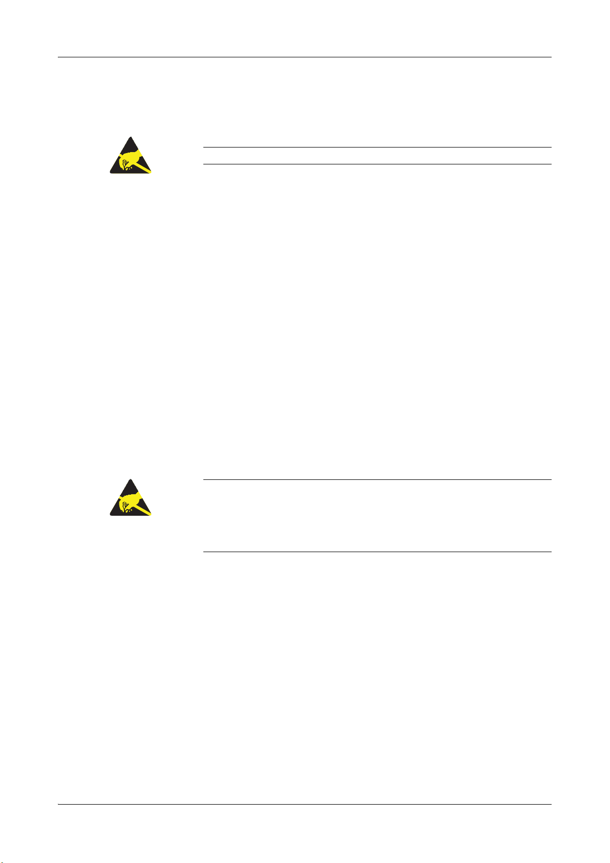
ESD protection measures All sections or passages that are marked with this
symbol warn of specific dangers in connection
with static discharge. Packages that are marked
with this symbol must only be opened by trained
technical staff.
Invisible Laser Radiation Avoid direct radiation to eyes
Laser Class 3R according to EN 60825-1
P0 < 5 mW
λ = 635 - 850 nm
e
For more information about warning symbols, refer to the cobas b 221 system Intructions
for Use.
e
For more information about ESD protection measures, see ESD protection measures on
page A-8.
Roche Diagnostics May 2009
8 Service Manual · Version 9.0

cobas b 221 system
Abbreviations The following abbreviations are used:
Abbreviation Definition
A
ADC Analogue to digital converter
ANSI American National Standards Institute
AQC AutoQC
B
BG Blood Gases
C
CCD Charge coupled device
CMOS Complementary Metal-Oxide Semiconductor
E
EEPROM Electrically erasable programmable read-only memory
e.g. exempli gratia – for example
EC European community
EN European standard
ESD Electro Static Discharge
F
FMS Fluid Mixing System
FTP File Transfer Protocol
H
HIV Human Immunodeficiency Virus
HW Hardware
I
IEC International Electrical Commission
IfS Interference sensor (part of the MSS cartridge)
ISE Ion selective electrode
IVD In vitro Diagnostics
L
LCD Liquid Cristal Display
M
MC Measuring chamber
MOS Metal-Oxide Semiconductor
MSDS Material safety data sheet
MSS Metabolite Sensitive Sensor
Q
QC Quality control
R
REF Reference solution for ISE module
S
S1 S1 Rinse Solution
S2 S2 Fluid Pack
S3 S3 Fluid Pack A
Roche Diagnostics May 2009
Service Manual · Version 9.0 9

Abbreviation Definition
SCD Sample container detection
SD Sample distributor
SIP Sample inlet path
SW Software
T
T&D Turn and Dock
TTL Transisitor-Transistor Logic
U
USB Universal Serial Bus
V
V19 Valve 19
VM FMS Mixing Valve
VPP (=VPS) Vacuum pump protector
cobas b 221 system
Roche Diagnostics May 2009
10 Service Manual · Version 9.0

System Description
1 Safety information . . . . . . . . . . . . . . . . . . . . . . . . . . . . . . . . . . . A-3
2 Fluid actions . . . . . . . . . . . . . . . . . . . . . . . . . . . . . . . . . . . . . . . A-11
A
May 2009


cobas b 221 system 1 Safety information
Tab le of co nt ent s
Safety information
Before the maintenance and repair of the cobas b 221 system, it is essential that the
warnings, cautions, and safety requirements contained in this manual are read and
understood by the user.
In this chapter
Important information ................................................................................................... 5
Operating safety information ......................................................................................... 6
Important notes and warnings ....................................................................................... 6
Disinfectants .................................................................................................................... 7
Deproteinizer .............................................................................................................7
Other disinfectants .................................................................................................... 7
ESD protection measures ................................................................................................ 8
Explanation of the phenomenon .............................................................................. 8
Influence of electrostatic charges on components ................................................... 8
Why is ESD protection so important today? ............................................................9
How can ESD protection be guaranteed? .................................................................9
Conclusion .................................................................................................................9
Chapter
1
Roche Diagnostics May 2009
Service Manual · Version 9.0 A-3

1 Safety information cobas b 221 system
Tab le of co nt ent s
Roche Diagnostics May 2009
A-4 Service Manual · Version 9.0

cobas b 221 system 1 Safety information
Important information
Important information
This Service Manual contains vital warning and safety information.
This instrument is only intended for one area of application which is described in the
instructions. The most important prerequisites for use, operation, and safety are
explained to ensure smooth operation. No warranty or liability claims will be covered
if the instrument is used in ways other than those described or if the necessary
prerequisites and safety measures are not observed.
The instrument may be operated only by persons whose qualifications enable them to
comply with the safety measures that are necessary during operation of the
instrument.
To avoid direct contact with biological materials, always wear appropriate protective
equipment such as lab clothing, protective gloves, safety glasses and, if necessary, a
face mask. Additionally a face shield must be worn if there is a potential of a
splashback. Appropriate disinfection and sterilization procedures must be followed.
To avoid direct contact with biological materials, wear lab clothing, protective gloves,
protective glasses and, if necessary, mouth cover and apply disinfection and
sterilization procedures.
Explanation
Adjustments and maintenance performed with removed covers and connected power
may be attempted only by a qualified technician who is aware of the associated
dangers.
Instrument repairs are only to be performed by the manufacturer or qualified service
personnel.
Only accessories and supplies either delivered by or approved by Roche are to be used
with the instrument. This ensures the performance and measuring accuracy of the
unit. These items are manufactured especially for use with this instrument and meet
the highest quality requirements.
Operation of the instrument with solutions whose composition is not consistent with
that of the original solutions' can negatively affect, above all, the long-term
measurement accuracy. Deviations in the composition of the solutions can also
decrease the service life of the electrodes.
The quality control requirements must be completed at least once daily for safety
reasons. Because the measurement results delivered by the instrument depend not
only on the instrument's proper operation but also on a variety of external influences
(for example: preanalytics), the results produced by this instrument should be
appraised by an expert before additional measures are taken based on the results.
Meaning: Important, see the cobas b 221 system Instructions for Use.
Roche Diagnostics May 2009
Service Manual · Version 9.0 A-5
1 Safety information cobas b 221 system
Operating safety information
Operating safety information
The instrument has been constructed and tested according to the following
European Standards:
o IEC/EN 61010-1
o IEC/EN 61010-2-101
o IEC/EN 61010-2-081 + A1
It was delivered from the factory in flawless condition with regards to safety features.
In order to preserve this condition and ensure safe operation, the user must respect
the notices and warnings that are contained in this Service manual.
o This equipment is a Class I laser product, and it complies with FDA Radiation
Performance Standards, 21 CFR Subchapter J (only valid for cobas b 221<1/3/5>
systems with tHb/SO
o This instrument is classified under the protection class I according to
IEC/EN 61010-1.
o The instrument meets the conditions for overvoltage category II.
o The instrument meets the conditions for contamination level 2.
o Do not operate the instrument in an explosive environment or in the vicinity of
explosive anesthetic mixtures containing oxygen or nitrous oxide.
o If objects or liquids enter the internal areas of the instrument, remove the
instrument from its power supply and allow an expert to check it thoroughly
before using it again.
o The instrument is suitable for long-term operation indoors.
module).
2
o
The power cord may be plugged only into a grounded socket. When using an extension cord,
make sure it is properly grounded.
o
Any rupture of the ground lead inside or outside the instrument or a loose ground connection
can render hazardous operation of the instrument. Intentional disconnection of the grounding
is not permitted.
o
The instrument is not suitable for operation with a direct current power supply. Use only the
original mains plug delivered with the cobas b 221 system.
o
The use of controls or adjustments or performance of procedures other than those specified
herein may result in hazardous radiation exposure.
Important notes and warnings
o
Never operate the analyzer in the vicinity of volatile or explosive gases
(e.g. anesthetic gases, etc.)!
o
The instrument must be connected to a 2-pin, grounded socket.
o
The power cable and the plug must be undamaged. Damaged power cables and plugs must be
replaced immediately.
o
Before opening the back panel switch off the instrument and disconnect the power cable.
o
Replace damaged fuses with the specified type of fuse.
Roche Diagnostics May 2009
A-6 Service Manual · Version 9.0
cobas b 221 system 1 Safety information
Disinfectants
o
Service and repair work must be done only as specified in this manual. Unqualified service or
repair work may result in warranty claims not being granted.
o
Use only suitable tools and test instruments for service and repair work.
o
Do not allow fluids to enter the interior of the instrument, because this may damage the
electronics.
o
Use only slightly moistened cloths or cotton sticks to clean the instrument.
Disinfectants
Use only liquid disinfectant such as protein remover (Roche deproteinizer) or an alcohol-based
(about 70%) surface disinfectant.
Do not spray disinfectant directly onto the instrument because this could cause malfunctions in the
electronics.
Do not use any type of bleaching agent. Exception: Roche Deproteinizer.
Deproteinizer
Composition Aqueous NaOCl solution with active chlorine (≤ 2%)
Hazards identification Due to the basic and oxidizing character of the reagent ("Deproteinizer") local
First aid measures
Other disinfectants
Do not attempt to clean/decontaminate any part of the instrument before shutting it down and
unplugging it from the power source.
Before plugging in the instrument again and switching it on always wait for 15 minutes to allow the
disinfectant to evaporate.
irritations after contact with eyes, skin or mucous membranes cannot be excluded.
After inhalation:
After skin contact:
After eye contact:
After drinking:
breath fresh air, drink large amounts of water
wash with generous amounts of water, remove contaminated clothing
rinse eyes with generous amounts of water, contact an eye specialist
drink large amounts of water, avoid vomiting, contact a doctor
Use standard alcohol-based (70%) disinfectants to clean the surface of the
instrument. Read the product information first.
Never use standard disinfectant to clean the tubes and tubing paths under any circumstances!
Do not use any type of bleaching agent. Exception: Roche Deproteinizer.
Roche Diagnostics May 2009
Service Manual · Version 9.0 A-7
1 Safety information cobas b 221 system
ESD protection measures
ESD protection measures
ESD = Electrostatic Sensitive Device
Explanation of the phenomenon
The most frequent cause of electrostatic discharge is friction of various materials such
as plastic, synthetic fiber, hard rubber or paper.
It can also be caused by bending or applying pressure to a material.
Discharges that are dangerous to components occur when "charged" bodies or
components do not have a discharge connection (ground) to discharge the
electrostatic charge.
The discharges normally do not have a high capacity, but there are often voltage
differences in the range of several thousand volts. The discharges are perceived as
small shocks or visible sparks.
Examples: o Shoes with rubber soles:
Friction is caused by walking. A person develops an electrical charge different
from the ground. A discharge occurs when an object (e.g. door handle) is
contacted.
o Synthetic fiber clothing:
Discharge is audible and is visible in darkness.
The dryer the air the greater the risk of electrical discharge caused by friction.
Eectrostatic charges are less likely to build up in humid air, particularly when saturated with water
vapor.
The probability of ESD phenomena is therefore particularly great in a northern hemisphere winter
in centrally heated rooms where the humidity is low.
Influence of electrostatic charges on components
If a person with an electrostatic charge touches a component, a discharge over a
connection of an IC or semiconductor element may occur. The resulting voltages may
damage the component.
Critical situations can occur while repairing or testing components if they are lying
on a more or less conductive surface (e.g. table top) and a person with an electrostatic
charge touches them. A discharge through a critical component connection can also
occur in this case.
Roche Diagnostics May 2009
A-8 Service Manual · Version 9.0

cobas b 221 system 1 Safety information
ESD protection measures
Why is ESD protection so important today?
Formerly, current controlling semiconductors were mostly used (TTL, normal
transistors, etc.).
Today the principle of current logic is virtually the only technology in use in MOS
and CMOS components.
Currents generated by an electrostatic discharge (as much as several kV!) destroy the
sensitive component inputs or cause hidden damage. This damage is generally not
immediately detectable.
Another effect is that the clearances inside the ICs continuously become smaller. The
internal wires become thinner and thinner, the allowable maximum input voltages
become smaller and the effects of any discharges become more and more critical.
How can ESD protection be guaranteed?
A continuous discharge is required when working on an electronic assembly. Do this
as follows:
o Use ESD wrist bands (special wrist bands connected to a protective ground).
o Repairs and tests on assemblies must only be conducted on tables with ESD mats
connected to grounds or ESD wrist bands.
o Always pick up components at the edge (e.g. like a photo).
o Components must always be transported in ESD packages or appropriate storage
or shipping containers (use original packaging!).
o Shoes with rubber soles or clothing of synthetic fibers must not be worn in
workshops where electronic components are repaired.
o Use a humidifier if necessary to maintain optimum humidity in the work area.
o Do not touch assemblies or components with the hand after testing.
o Always transport and ship assemblies or components for repair in ESD protective
packaging only. This will prevent further damage that may result in
misinterpretation of the original cause of the fault.
The ESD mat consists of materials that have a very low, defined conductivity (1012 ohms).
The following materials prevent charges caused by friction from building up and protect the
component from damage.
o
ESD mats
o
ESD packages
o
Shipping containers
Conclusion
Of course, not all circuit boards and electronic assemblies require such careful
handling. An electrical board that only carries simple plug connectors does not
require ESD packaging.
In cases of doubt always use ESD packaging.
Roche Diagnostics May 2009
Service Manual · Version 9.0 A-9

1 Safety information cobas b 221 system
ESD protection measures
Roche Diagnostics May 2009
A-10 Service Manual · Version 9.0

cobas b 221 system 2 Fluid actions
Tab le of co nt ent s
Fluid actions
This chapter provides information about the fluidic actions of the cobas b 221 system.
In this chapter
Fluid actions overview ..................................................................................................13
cobas b 221<1> system ...........................................................................................13
cobas b 221<2> system ...........................................................................................14
cobas b 221<3> system ...........................................................................................15
cobas b 221<4> system ...........................................................................................16
cobas b 221<5> system ...........................................................................................17
cobas b 221<6> system ...........................................................................................18
Pin assignment of S2 and S3 Fluid Packs ..................................................................... 19
S2 Fluid Pack ............................................................................................................19
S3 Fluid Pack A (cobas b 221<5/6> systems only) ................................................ 19
T&D positions ...............................................................................................................20
Measurement .................................................................................................................21
Sample input ............................................................................................................ 21
Sample distribution ................................................................................................. 23
Aspirating MSS standby solution and starting FMS .............................................25
Washing the measuring chamber vicinity ..............................................................27
Wash i ng t Hb/ SO
Recalibrating BG/ISE and drying tHb/SO
Calibration .....................................................................................................................31
BG/ISE cleaning ....................................................................................................... 31
Calibrating the conductivity for CAL A or CAL B ................................................32
O
zero point calibration ........................................................................................34
2
Na conditioning .......................................................................................................35
Mix1/Mix2 calibration, aspirating BG/ISE reference solution .............................36
O2-air calibration .................................................................................................... 38
Aspirating MSS reference solution, calibration with standby solution ................ 39
CAL 1 Calibration ...................................................................................................41
or COOX and preparing Mix1 .................................................28
2
or COOX ...........................................29
2
Chapter
2
Roche Diagnostics May 2009
Service Manual · Version 9.0 A-11

2 Fluid actions cobas b 221 system
Tab le of co nt ent s
CAL 2/CAL 3/CAL 4 Calibration ........................................................................... 42
COOX calibration ...................................................................................................43
Roche Diagnostics May 2009
A-12 Service Manual · Version 9.0
cobas b 221 system 2 Fluid actions
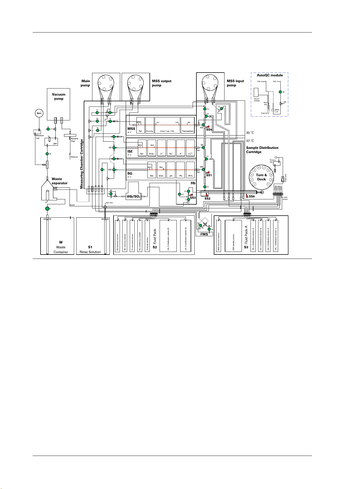
Fluid actions overview
Fluid actions overview
cobas b 221<1> system
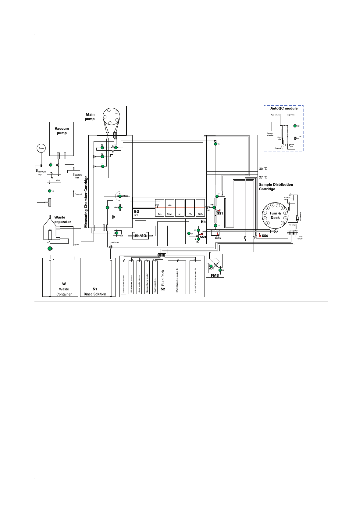
Figure A-1 cobas b 221<1> system
Roche Diagnostics May 2009
Service Manual · Version 9.0 A-13
2 Fluid actions cobas b 221 system
Fluid actions overview
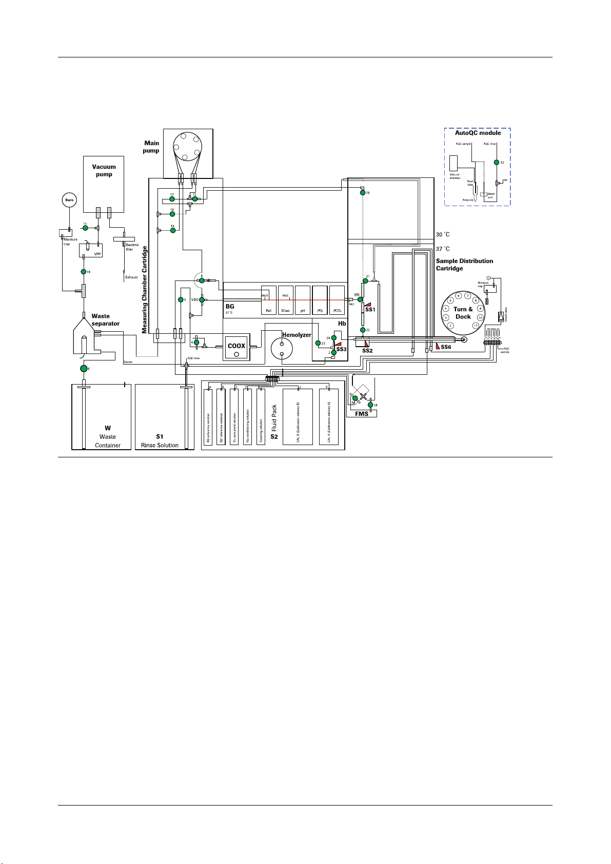
cobas b 221<2> system
Figure A-2 cobas b 221<2> system
Roche Diagnostics May 2009
A-14 Service Manual · Version 9.0
cobas b 221 system 2 Fluid actions
Fluid actions overview
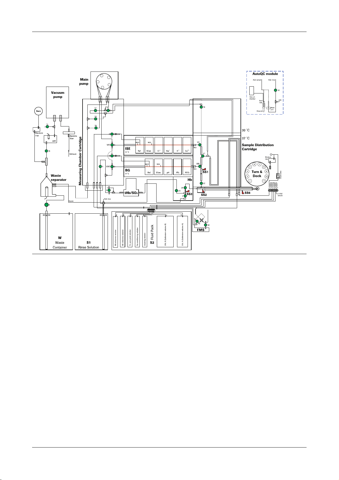
cobas b 221<3> system
Figure A-3 cobas b 221<3> system
Roche Diagnostics May 2009
Service Manual · Version 9.0 A-15
2 Fluid actions cobas b 221 system
Fluid actions overview
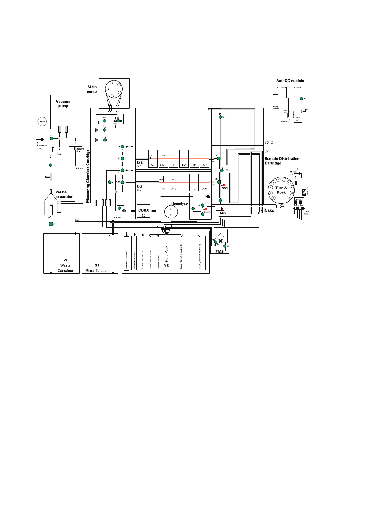
cobas b 221<4> system
Figure A-4 cobas b 221<4> system
Roche Diagnostics May 2009
A-16 Service Manual · Version 9.0
cobas b 221 system 2 Fluid actions
Fluid actions overview
cobas b 221<5> system
Figure A-5 cobas b 221<5> system
Roche Diagnostics May 2009
Service Manual · Version 9.0 A-17

2 Fluid actions cobas b 221 system
Fluid actions overview
cobas b 221<6> system
Figure A-6 cobas b 221<6> system
Roche Diagnostics May 2009
A-18 Service Manual · Version 9.0
cobas b 221 system 2 Fluid actions
C
D
F
E
B
A
G
H
C
D
F
E
B
A
G
H
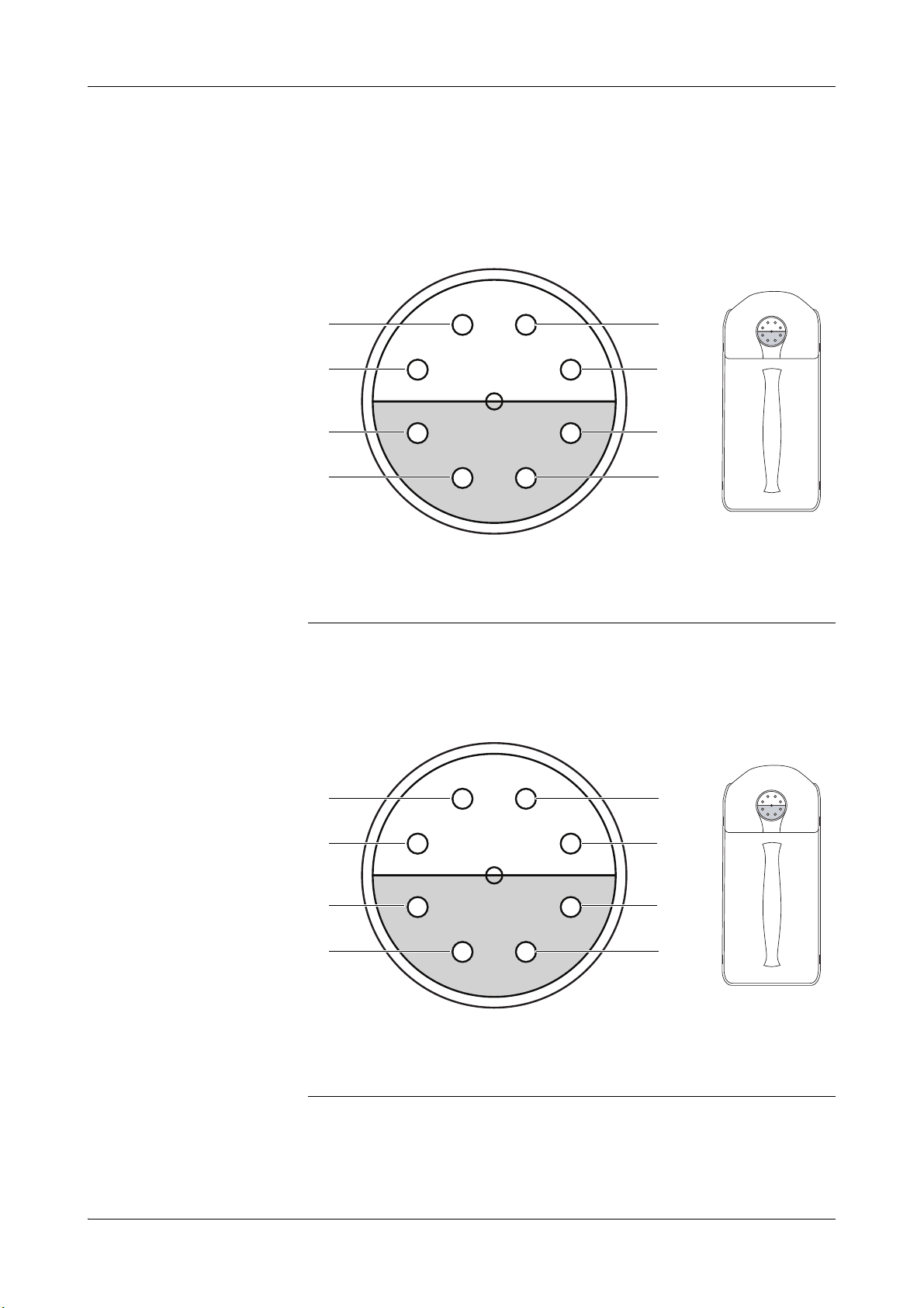
Pin assignment of S2 and S3 Fluid Packs
Pin assignment of S2 and S3 Fluid Packs
S2 Fluid Pack
A O2 zero point solution
B CAL B (calibration solution)
C CAL A (calibration solution)
D empty
Figure A-7 Pin assignment of S2 Fluid Pack
S3 Fluid Pack A (cobas b 221<5/6> systems only)
E ISE reference solution
F BG reference solution
G Na conditioning solution
H Cleaning solution
A CAL 2 (calibration solution 2)
B MSS standby solution
C CAL 1 (calibration solution 1)
Roche Diagnostics May 2009
Service Manual · Version 9.0 A-19
D empty
Figure A-8 Pin assignment of S3 Fluid Pack A
E empty
F MSS reference solution
G CAL 4 (calibration solution 4)
H CAL 3 (calibration solution 3)

2 Fluid actions cobas b 221 system
D
C
A
B
E
F
I
J
K
H
G
T&D positions
T&D positions
A 1: Releases the fill port for placing a sample
B 2: S1 Rinse Solution
C 3: Position for "aspiration from the syringe“
D 4: Dock position
E 5: O
F 6: CAL 2 from S3 Fluid Pack A
Figure A-9 T&D positions
zero point solution from S2 Fluid Pack
2
(cobas b 221<5/6> systems only)
G 7: Na conditioning solution from S2 Fluid
Pack
H 8: CAL 3 from S3 Fluid Pack A
(cobas b 221<5/6> systems only)
I 9: Cleaning solution from S2 Fluid Pack
J 10: AutoQC connection
K 11: CAL 4 from S3 Fluid Pack A
(cobas b 221<5/6> systems only)
Roche Diagnostics May 2009
A-20 Service Manual · Version 9.0
Loading...