


 Loading...
Roche Diagnostics / Hitachi
cobas e 411
Service Manual Version 1.0
May 2006
Service Manual
for cobas e411
Immunoassay
System
Revision Record |
|
|
Date Number |
Version |
New Chapter |
January 2006 |
Draft |
|
May 2006 |
1.0 |
|
Note
Part No. and Part name are different depending on the manufacturing time. Please refer to Parts List for details.
RD/Hitachi Immunoassay System cobas e411 Service Manual
1.Application/Introduction
1.1Instrument
1.2Specifications
1.3Operating Precautions and Hazards
1.4Service Concept
1.5Rack Sampler/Rack Conveyor System
2. |
Installation / Set Up |
|
2.1 |
Site Requirements |
|
2.2 |
Inventory |
|
2.3 |
Analyzer Installation |
|
2.4 |
Software Installation |
|
2.5 |
Rack Sampler Connected to CLAS 1 System Installation |
|
2.6 |
Check/Adjustment During Installation |
|
3. |
|
Fludics |
3.1Description of Flow Path
3.2System Volume
3.3Cleaning Procedures
3.4SysWash
4.Mechanics
4.1Overview
4.2Location of Mechanisms
4.3List of Motors, Sensors and Other Mechanisms
4.4Detailed Explanation of Each Mechanism
4.5Mechanical Adjustment
4.6Rack Sampler System
5.Electronics
5.1Boards
5.2Power Source
5.3Electronic Modules
5.4Printed Circuit Boards
5.5Cross Wiring Diagrams
5.6How to Check Photo Interrupters
6.Service Software
6.1 Overview
1
7.Troubleshooting
7.1. Alarms List
7.2Data Alarms
7.3Troubleshooting List
7.4Data File Load Errors
7.5Quality Control Check
8.Spare Parts/Recommended Parts
8.1Special Service Tools
8.2Complete Recommended Parts List
8.3Printed Circuit Boards List
9.Host Interface (not applicable)
10.Maintenance
10.1Operator Maintenance
10.2Preventive Maintenance
10.3Maintenance Material
Appendix
Timing Chart Tables
Assay Timetable
2

System Description
Chapter 1 System Description
1.1 INSTRUMENT .............................................................................................................................................. |
1 |
- 1 |
1.1.1 System Configuration ........................................................................................................................ |
1 - 1 |
|
1.1.2 System Introduction........................................................................................................................... |
1 - 2 |
|
1.1.3 Control Unit Components ................................................................................................................. |
1 - 5 |
|
1.1.4 Sample/Reagent Area Components ................................................................................................... |
1 - 7 |
|
1.1.5 Consumables Area Components...................................................................................................... |
1 - 22 |
|
1.1.6 Measuring Area Components.......................................................................................................... |
1 - 27 |
|
1.1.7 Power Components ......................................................................................................................... |
1 - 33 |
|
1.1.8 Mechanical Theory.......................................................................................................................... |
1 - 35 |
|
1.1.9 Detailed Assay Sequence................................................................................................................. |
1 - 38 |
|
1.1.10 Dilution Steps................................................................................................................................ |
1 - 47 |
|
1.1.11 Analyzer Status Conditions ........................................................................................................... |
1 - 48 |
|
1.2 TECHNICAL DATA .................................................................................................................................... |
1 - 52 |
|
1.2.1 Technical Data for Operation of Instrument................................................................................... |
1 - 52 |
|
1.3 POTENTIAL HAZARD AND SAFETY PRECAUTIONS .................................................................................... |
1 - 61 |
|
1.3.1 Safety Classifications ...................................................................................................................... |
1 - 61 |
|
1.3.2 Safety Information........................................................................................................................... |
1 - 62 |
|
1.3.3 Safety Labels on the cobas e411...................................................................................................... |
1 - 68 |
|
1.3.4 Approvals ........................................................................................................................................ |
1 - 70 |
|
1.4 SYSTEM LABEL ........................................................................................................................................ |
1 - 71 |
|
1.4.1 Disk System ..................................................................................................................................... |
1 - 71 |
|
1.4.2 Rack System..................................................................................................................................... |
1 - 73 |
|
Contents - 1

Installation / Set Up
Chapter 2 Installation / Set Up
2.1 SITE REQUIREMENTS.................................................................................................................................. |
2 |
- 1 |
2.1.1 Delivery Space Requirements............................................................................................................ |
2 - 1 |
|
2.1.2 Physical Space and weighs Requirements......................................................................................... |
2 - 1 |
|
2.1.3 Ambient Condition Requirements...................................................................................................... |
2 - 3 |
|
2.1.4 Electrical Requirements .................................................................................................................... |
2 - 3 |
|
2.1.5 Water Requirements .......................................................................................................................... |
2 - 3 |
|
2.2 INVENTORY................................................................................................................................................ |
2 |
- 4 |
2.3 ANALYZER INSTALLATION......................................................................................................................... |
2 |
- 7 |
2.3.1 Unpacking ......................................................................................................................................... |
2 - 7 |
|
2.3.2 Explanation of Packaging Position in the System........................................................................... |
2 - 14 |
|
2.3.3 Panel PC Installation and confirmation of AC Power Supply ........................................................ |
2 - 21 |
|
2.3.4 Setup................................................................................................................................................ |
2 - 25 |
|
2.3.5 Mounting a Measuring Cell ............................................................................................................ |
2 - 25 |
|
2.3.6 Installation of System Software ....................................................................................................... |
2 - 26 |
|
2.3.7 Fill Liquid System ........................................................................................................................... |
2 - 26 |
|
2.3.8 Adjustments to be Checked During Installation and After Replacement......................................... |
2 - 26 |
|
2.3.9 Measuring Cell Preparation ........................................................................................................... |
2 - 27 |
|
2.3.10 System Volume Check.................................................................................................................... |
2 - 28 |
|
2.3.11 High Voltage Check/Adjustment ................................................................................................... |
2 - 28 |
|
2.3.12 Initial BlankCell Calibrations....................................................................................................... |
2 - 35 |
|
2.3.13 Instrument Checks......................................................................................................................... |
2 - 39 |
|
2.3.14 Assay Calibration.......................................................................................................................... |
2 - 51 |
|
2.3.15 Installation Procedures Overview / Checklist............................................................................... |
2 - 51 |
|
2.3.16 Procedure for Multiple Installations............................................................................................. |
2 - 51 |
|
2.4 SOFTWARE INSTALLATION ....................................................................................................................... |
2 - 53 |
|
2.4.1 Application Instruction.................................................................................................................... |
2 - 53 |
|
2.4.2 Printer Driver Instruction ............................................................................................................... |
2 - 58 |
|
2.4.3 System Parameter Setup.................................................................................................................. |
2 - 69 |
|
2.5 RACK SAMPLER SYSTEM INSTALLATION.................................................................................................. |
2 - 70 |
|
2.5.1 Rack Sampler System Installation ................................................................................................... |
2 - 70 |
|
2.6 CHECKS/ADJUSTMENTS DURING INSTALLATION ..................................................................................... |
2 - 84 |
|
2.6.1 Bead Mixer...................................................................................................................................... |
2 - 84 |
|
2.6.2 Pipetter Adjustment......................................................................................................................... |
2 - 86 |
|
2.6.3 Sipper adjustment............................................................................................................................ |
2 - 86 |
|
2.6.4 Electronic adjustments .................................................................................................................... |
2 - 86 |
|
2.6.5 Rack Sampler adjustments .............................................................................................................. |
2 - 86 |
|
2.7 TABLE OF CONTENTS ............................................................................................................................... |
2 - 92 |
|
2.7.1 Method to detach the external covers.............................................................................................. |
2 - 92 |
|
2.7.2 Method to attach the external covers .............................................................................................. |
2 - 99 |
|
2.7.3 Mmethod to detach the PC Unit.................................................................................................... |
2 - 107 |
|
2.7.4 Method to attach the PC Unit ....................................................................................................... |
2 - 109 |
|
Contents - 1

Fluidics
Chapter 3 Fluidics |
|
3.1 DESCRIPTION OF FLOW PATH..................................................................................................................... |
3 - 1 |
3.1.1 Overall Piping Diagram.................................................................................................................... |
3 - 2 |
3.1.2 List of Parts....................................................................................................................................... |
3 - 3 |
3.2 SYSTEM VOLUME....................................................................................................................................... |
3 - 3 |
3.2.1 Definition of System Volume ............................................................................................................. |
3 - 3 |
3.2.2 Determination of System Volume ...................................................................................................... |
3 - 3 |
3.2.3 Storage of the System Volume Value / Data Handling...................................................................... |
3 - 4 |
3.3 CLEANING PROCEDURES ............................................................................................................................ |
3 - 5 |
3.3.1 Liquid Flow Cleaning ....................................................................................................................... |
3 - 5 |
3.3.2 Cleaning Procedure for Fluidics System........................................................................................... |
3 - 6 |
3.4 SYSWASH .................................................................................................................................................. |
3 - 8 |
3.4.1 Introduction....................................................................................................................................... |
3 - 8 |
3.4.2 SysWash Rinsing Procedure.............................................................................................................. |
3 - 8 |
Contents - 1

Mechanics
Chapter 4 Mechanics
4.1 OVERVIEW ................................................................................................................................................. |
4 |
- 1 |
4.1.1 Location ............................................................................................................................................ |
4 - 1 |
|
4.1.2 Outline of Mechanical Units ............................................................................................................. |
4 - 1 |
|
4.2 LOCATION OF MECHANISMS ...................................................................................................................... |
4 |
- 3 |
4.2.1 Analyzer ............................................................................................................................................ |
4 - 3 |
|
4.2.2 Rack Sampler System ........................................................................................................................ |
4 - 6 |
|
4.3 LIST OF MOTORS, SENSORS, AND OTHER MECHANISMS .......................................................................... |
4 - 10 |
|
4.3.1 List of Motors .................................................................................................................................. |
4 - 10 |
|
4.3.2 Motor Reference List....................................................................................................................... |
4 - 10 |
|
4.3.3 List of Sensors ................................................................................................................................. |
4 - 10 |
|
4.3.4 List of Peltier, Heater and Fan Motor ............................................................................................ |
4 - 11 |
|
4.3.5 List of Motors for Rack Sampler System ......................................................................................... |
4 - 12 |
|
4.3.6 List of Sensors for Rack Sampler System ........................................................................................ |
4 - 12 |
|
4.3.7 List of LEDs and Fan Motor for Rack Sampler System .................................................................. |
4 - 12 |
|
4.4 DETAILED EXPLANATION OF EACH MECHANISM ..................................................................................... |
4 - 13 |
|
4.4.1 Sample Disk Drive Mechanism ....................................................................................................... |
4 - 13 |
|
4.4.2 Reagent Disk Drive Mechanism...................................................................................................... |
4 - 19 |
|
4.4.3 Cap Open/Close Mechanism........................................................................................................... |
4 - 28 |
|
4.4.4 Beads Mixer Mechanism ................................................................................................................. |
4 - 33 |
|
4.4.5 Pipetter Mechanism ........................................................................................................................ |
4 - 40 |
|
4.4.6 Gripper Mechanism ........................................................................................................................ |
4 - 52 |
|
4.4.7 Sipper Mechanism........................................................................................................................... |
4 - 66 |
|
4.4.8 System Reagent Mechanism ............................................................................................................ |
4 - 74 |
|
4.4.9 Syringe Mechanism ......................................................................................................................... |
4 - 77 |
|
4.4.10 System Water Container (Float SW) Mechanism / Pump Assembly.............................................. |
4 - 81 |
|
4.4.11 Liquid Waste Container Mechanism ............................................................................................. |
4 - 87 |
|
4.4.12 Solid Waste Mechanism ................................................................................................................ |
4 - 91 |
|
4.4.13 Detection Unit ............................................................................................................................... |
4 - 94 |
|
4.4.14 Magnet Drive Mechanism ........................................................................................................... |
4 - 105 |
|
4.4.15 Matrix BCR Mechanism .............................................................................................................. |
4 - 110 |
|
4.4.16 SIPPER SAFETY COVER (INTER ROCK Mechanism).............................................................. |
4 - 121 |
|
4.5 MECHANICAL ADJUSTMENT................................................................................................................... |
4 - 123 |
|
4.5.1 Overview ....................................................................................................................................... |
4 - 123 |
|
4.5.2 Mechanical Adjustment Procedure ............................................................................................... |
4 - 123 |
|
4.5.3 Mechanical Adjustment Procedure for Rack Sampler .................................................................. |
4 - 129 |
|
4.6 RACK SAMPLER SYSTEM........................................................................................................................ |
4 - 132 |
|
4.6.1 Overview ....................................................................................................................................... |
4 - 132 |
|
4.6.2 Rack Sampler Movement............................................................................................................... |
4 - 132 |
|
4.6.3 A Line ............................................................................................................................................ |
4 - 133 |
|
4.6.4 B Line ............................................................................................................................................ |
4 - 134 |
|
4.6.5 C Line............................................................................................................................................ |
4 - 137 |
|
Contents - 1

Electronics
Chapter 5 Electronics
5.1 BOARDS ..................................................................................................................................................... |
5 |
- 1 |
5.1.1 System Overview ............................................................................................................................... |
5 - 1 |
|
5.1.2 Location of Boards............................................................................................................................ |
5 - 2 |
|
5.2 POWER SOURCE ....................................................................................................................................... |
5 - 10 |
|
5.2.1 AC Power ........................................................................................................................................ |
5 - 10 |
|
5.2.2 DC Power Supply............................................................................................................................ |
5 - 11 |
|
5.3 ELECTRONIC MODULES / ELECTRONIC ADJUSTMENTS............................................................................. |
5 - 17 |
|
5.3.1 Principle of Temperature Control................................................................................................... |
5 - 17 |
|
5.3.2 Principle of LLD ............................................................................................................................. |
5 - 18 |
|
5.3.3 Principle of Clot Detection ............................................................................................................. |
5 - 20 |
|
5.3.4 Adjustment / Check Procedure of LLD/Clot Detection ................................................................... |
5 - 20 |
|
5.3.5 Functional Details of FRONT SW (Operation Switch) ................................................................... |
5 - 27 |
|
5.3.6 Details of Temperature Control / Troubleshooting of Temp. Units ................................................ |
5 - 28 |
|
5.3.7 Serial Data Communication............................................................................................................ |
5 - 31 |
|
5.3.8 Adjustment of Mixer Speed.............................................................................................................. |
5 - 32 |
|
5.4 PRINTED CIRCUIT BOARDS....................................................................................................................... |
5 - 33 |
|
5.4.1 ECPU550 Board ............................................................................................................................. |
5 - 33 |
|
5.4.2 EECL300 Board.............................................................................................................................. |
5 - 36 |
|
5.4.3 EMOT300 Board............................................................................................................................. |
5 - 38 |
|
5.4.4 EIO3 Board ..................................................................................................................................... |
5 - 42 |
|
5.4.5 DO1 Board...................................................................................................................................... |
5 - 44 |
|
5.4.6 DO2 Board...................................................................................................................................... |
5 - 47 |
|
5.4.7 DO3 Board...................................................................................................................................... |
5 - 48 |
|
5.4.8 DIST-PA Board ............................................................................................................................... |
5 - 50 |
|
5.4.9 DIST-SA Board................................................................................................................................ |
5 - 51 |
|
5.4.10 DIST-TVA Board........................................................................................................................... |
5 - 52 |
|
5.4.11 DIST-F Board................................................................................................................................ |
5 - 52 |
|
5.4.12 DIST-F3 Board.............................................................................................................................. |
5 - 54 |
|
5.4.13 DIST232C Board........................................................................................................................... |
5 - 55 |
|
5.4.14 ANG-EP2 Board............................................................................................................................ |
5 - 56 |
|
5.4.15 PMT-SHV2 Board ......................................................................................................................... |
5 - 59 |
|
5.4.16 L-AMP(3) Board ........................................................................................................................... |
5 - 60 |
|
5.4.17 LLD-SA Board............................................................................................................................... |
5 - 62 |
|
5.4.18 LLD-P3 Board............................................................................................................................... |
5 - 63 |
|
5.4.19 UIRS-C Board ............................................................................................................................... |
5 - 64 |
|
5.4.20 MVLB110 Board ........................................................................................................................... |
5 - 65 |
|
5.4.21 S.AB-CE Board ............................................................................................................................. |
5 - 66 |
|
5.4.22 DET-A Board ................................................................................................................................ |
5 - 67 |
|
5.4.23 DET-B Board ................................................................................................................................ |
5 - 68 |
|
5.4.24 DET-C Board ................................................................................................................................ |
5 - 68 |
|
5.4.25 DETECT1 Board........................................................................................................................... |
5 - 69 |
|
5.4.26 RS CONTD Doard......................................................................................................................... |
5 - 69 |
|
5.4.27 PS CONTA Board ......................................................................................................................... |
5 - 71 |
|
5.4.28 DO4A Board ................................................................................................................................. |
5 - 73 |
|
5.4.29 BCR Board .................................................................................................................................... |
5 - 75 |
|
5.4.30 PH-D Board .................................................................................................................................. |
5 - 76 |
|
5.4.31 PH-T Board................................................................................................................................... |
5 - 76 |
|
5.5 CROSS WIRING DIAGRAMS ...................................................................................................................... |
5 - 77 |
|
5.5.1 Cross Wiring Diagrams for Rack Sampler System.......................................................................... |
5 - 77 |
|
5.5.2 Cross Wiring Diagrams for Rack Sampler...................................................................................... |
5 - 77 |
|
5.6 HOW TO CHECK PHOTO INTERRUPTERS ................................................................................................... |
5 - 78 |
|
5.6.1 Photo Interrupters........................................................................................................................... |
5 - 78 |
|
5.6.2 How to check the PCPs ................................................................................................................... |
5 - 80 |
|
Contents - 1
Service Software
Chapter 6 Service Software
6.1 OVERVIEW ................................................................................................................................................. |
6 |
- 1 |
6.1.1 Utility Screen of Print ....................................................................................................................... |
6 - 4 |
|
6.1.2 Interface Setup ................................................................................................................................ |
6 - 10 |
|
6.1.3 System Setup.................................................................................................................................... |
6 - 13 |
|
6.1.4 Storage Utility ................................................................................................................................. |
6 - 15 |
|
6.1.5 Documentation and Printer Setting................................................................................................. |
6 - 18 |
|
6.1.6 Keep Function Setup ....................................................................................................................... |
6 - 20 |
|
6.1.7 Retry Function Setup....................................................................................................................... |
6 - 20 |
|
6.1.8 Sample Reception Mode.................................................................................................................. |
6 - 21 |
|
6.2 MAINTENANCE......................................................................................................................................... |
6 - 22 |
|
6.2.1 Detailed Description of Each Maintenance Function..................................................................... |
6 - 24 |
|
6.3 MECHANISM CHECK ................................................................................................................................ |
6 - 27 |
|
6.3.1 System Volume Check...................................................................................................................... |
6 - 31 |
|
6.3.2 Assay Performance Check............................................................................................................... |
6 - 31 |
|
6.3.3 Voltage Monitor .............................................................................................................................. |
6 - 39 |
|
6.3.4 Temperature Monitor ...................................................................................................................... |
6 - 40 |
|
6.3.5 Sensor Monitor................................................................................................................................ |
6 - 41 |
|
6.4 SERVICE ................................................................................................................................................... |
6 - 43 |
|
6.4.1 Manual Adjustment ......................................................................................................................... |
6 - 44 |
|
6.4.2 Adjustment Rack.............................................................................................................................. |
6 - 47 |
|
6.4.3 BCR Setup ....................................................................................................................................... |
6 - 49 |
|
6.4.4 Service Setup ................................................................................................................................... |
6 - 52 |
|
6.4.5 Service Maintenance ....................................................................................................................... |
6 - 53 |
|
6.4.6 Alarm Setting................................................................................................................................... |
6 - 55 |
|
6.4.7 Initial Blank Cell ............................................................................................................................. |
6 - 56 |
|
6.4.8 Automatic Adjustment ..................................................................................................................... |
6 - 59 |
|
Contents - 1

Troubleshooting
Chapter 7 Troubleshooting
7.1 ALARM LIST............................................................................................................................................... |
7 |
- 1 |
7.2 DATA ALARM LIST .................................................................................................................................... |
7 |
- 2 |
7.3 TROUBLESHOOTING LIST............................................................................................................................ |
7 |
- 4 |
7.3.1 Reagent Disk ..................................................................................................................................... |
7 - 4 |
|
7.3.2 Cap Opener ....................................................................................................................................... |
7 - 5 |
|
7.3.3 Beads Mixer ...................................................................................................................................... |
7 - 6 |
|
7.3.4 Barcode Reader Mechanism ............................................................................................................. |
7 - 8 |
|
7.3.5 Sample Disk Mechanism ................................................................................................................... |
7 - 8 |
|
7.3.6 Pipetter Mechanism .......................................................................................................................... |
7 - 9 |
|
7.3.7 Pipetter / Sipper Syringe ................................................................................................................. |
7 - 11 |
|
7.3.8 Gripper Mechanism ........................................................................................................................ |
7 - 12 |
|
7.3.9 Solid Waste...................................................................................................................................... |
7 - 15 |
|
7.3.10 Sipper Mechanism......................................................................................................................... |
7 - 16 |
|
7.3.11 Magnet Drive Mechanism ............................................................................................................. |
7 - 17 |
|
7.3.12 Pipetter Buffer............................................................................................................................... |
7 - 18 |
|
7.3.13 Distilled Water Float Switch ......................................................................................................... |
7 - 18 |
|
7.3.14 System Reagent Unit ..................................................................................................................... |
7 - 19 |
|
7.3.15 Liquid Waste Mechanism .............................................................................................................. |
7 - 19 |
|
7.3.16 Rack Sampler System .................................................................................................................... |
7 - 21 |
|
7.3.17 CF card problem ........................................................................................................................... |
7 - 22 |
|
7.4 QUALITY CONTROL CHECK...................................................................................................................... |
7 - 26 |
|
7.4.1 Covers ............................................................................................................................................. |
7 - 26 |
|
7.4.2 Sample/Assay Reagent Rotation Mechanism................................................................................... |
7 - 26 |
|
7.4.3 Cap Open/Close Mechanism........................................................................................................... |
7 - 26 |
|
7.4.4 Beads Mixer Mechanism ................................................................................................................. |
7 - 26 |
|
7.4.5 Barcode Reader Mechanism ........................................................................................................... |
7 - 26 |
|
7.4.6 Pipetter, Sipper Mechanism ............................................................................................................ |
7 - 27 |
|
7.4.7 Syringes Mechanism (after exchange); ........................................................................................... |
7 - 27 |
|
7.4.8 Gripper Mechanism ........................................................................................................................ |
7 - 27 |
|
7.4.9 solid Waste Mechanism................................................................................................................... |
7 - 27 |
|
7.4.10 1Incubation Unit ........................................................................................................................... |
7 - 27 |
|
7.4.11 1Detection Unit ............................................................................................................................. |
7 - 28 |
|
7.4.12 1Pump Module (after exchange);.................................................................................................. |
7 - 28 |
|
Contents - 1

Spare Parts/Recommended Parts
Chapter 8 Spare Parts/Recommended Parts
8.1 SPECIAL SERVICE TOOLS ........................................................................................................................... |
8 - 1 |
8.2 COMPLETE PARTS LIST .............................................................................................................................. |
8 - 2 |
Contents - 1

Host Interface
Chapter 9 Host Interface
9.1 HOST INTERFACE ....................................................................................................................................... |
9 - 1 |
Contents - 1

Maintenance
Chapter 10 Maintenance
10.1 MAINTENANCE PROCEDURE OVERVIEW ................................................................................................ |
10 |
- 6 |
10.1.1 Replace pipettor tube 510 ............................................................................................................. |
10 - 8 |
|
10.1.2 Replace pipettor tube 465 with nozzle seal ................................................................................. |
10 - 10 |
|
10.1.3 Replace Pinch Valve Tubing ....................................................................................................... |
10 - 13 |
|
10.1.4 Replace Pipettor Seals ................................................................................................................ |
10 - 15 |
|
10.1.5 Exchange packings for sipper & pipettor syringe....................................................................... |
10 - 22 |
|
10.1.6 Clean Rinse Stations for S/R Probe, Mixer and Sipper Probe .................................................... |
10 - 24 |
|
10.1.7 Clean Sipper and S/R probe ........................................................................................................ |
10 - 26 |
|
10.1.8 Clean water filter main pump...................................................................................................... |
10 - 29 |
|
10.1.9 Clean System Water Container ................................................................................................... |
10 - 31 |
|
10.1.10 Clean Liquid Waste Container.................................................................................................. |
10 - 33 |
|
10.1.11 Clean ProCell/CleanCell Compartments .................................................................................. |
10 - 34 |
|
10.1.12 Clean Reagent Disk and Compartment ..................................................................................... |
10 - 35 |
|
10.1.13 Check drain tubes for contamination and exchange if necessary ............................................. |
10 - 37 |
|
10.1.14 Drain the outlet pipettor wash station and waste pipe.............................................................. |
10 - 39 |
|
10.1.15 Perform Liquid Flow Cleaning ................................................................................................. |
10 - 39 |
|
10.1.16 Perform system volume check ................................................................................................... |
10 - 41 |
|
10.1.17 Exchange mixer belt S ............................................................................................................... |
10 - 41 |
|
10.1.18 Clean mixer paddle ................................................................................................................... |
10 - 42 |
|
10.1.19 Check mixer speed; adjust if necessary..................................................................................... |
10 - 43 |
|
10.1.20 Check / Clean gripper finger..................................................................................................... |
10 - 44 |
|
10.1.21 Clean light barriers and mechanic parts................................................................................... |
10 - 45 |
|
10.1.22 Clean Incubator and Aspiration Station.................................................................................... |
10 - 45 |
|
10.1.23 Check LLD voltage pipettor ...................................................................................................... |
10 - 47 |
|
10.1.24 Check LLD voltage sipper......................................................................................................... |
10 - 47 |
|
10.1.25 Check clot voltage ..................................................................................................................... |
10 - 47 |
|
10.1.26 Check Temperature Monitor for Detection unit........................................................................ |
10 - 47 |
|
10.1.27 Check Temperature Monitor for Incubator............................................................................... |
10 - 47 |
|
10.1.28 Check Temperature Monitor for Reagent.................................................................................. |
10 - 47 |
|
10.1.29 Check Temperature Monitor for PC / CC ................................................................................. |
10 - 47 |
|
10.1.30 Clean peltier elements from dust if necessary........................................................................... |
10 - 47 |
|
10.1.31 Clean BCR window and window reagent disk .......................................................................... |
10 - 49 |
|
10.1.32 Perform artificial media check.................................................................................................. |
10 - 50 |
|
10.1.33 Perform TSH assay test ............................................................................................................. |
10 - 50 |
|
10.1.34 Perform initial blank cell .......................................................................................................... |
10 - 50 |
|
10.1.35 Perform assay calibration......................................................................................................... |
10 - 50 |
|
10.1.36 Perform assay control ............................................................................................................... |
10 - 50 |
|
10.1.37 Exchange measuring cell .......................................................................................................... |
10 - 51 |
|
10.1.38 Exchange tube B for MC ........................................................................................................... |
10 - 52 |
|
10.1.39 Exchange tube B for sipper with nozzle seal ............................................................................. |
10 - 54 |
|
10.1.40 Exchange tube B for sipper syringe .......................................................................................... |
10 - 56 |
|
10.1.41 Clean the valve body on the system water container................................................................. |
10 - 58 |
|
10.1.42 Exchange O-ring SV 1 / 2 / 5 / 6 / 7 .......................................................................................... |
10 - 59 |
|
10.1.43 Exchange sipper wash station ................................................................................................... |
10 - 61 |
|
10.1.44 Exchange the spring at the gripper finger................................................................................. |
10 - 64 |
|
10.2 OPERATOR MAINTENANCE................................................................................................................... |
10 - 66 |
|
10.3 MAINTENANCE MATERIALS ................................................................................................................. |
10 - 67 |
|
Contents - 1

RD/Hitachi cobas e411 |
Service Manual |
1.1 Instrument
1.1.1 System Configuration
Figure 1.1-1 cobas e411 disk system
Figure 1.1-2 cobas e411 rack system
Version 1.0 – May 2006 |
1 - 1 |
Chapter 1.1 |

RD/Hitachi cobas e411 |
Service Manual |
1.1.2 System Introduction
The Roche Diagnostics cobas e411 Immunoassay System is a fully automated, software-controlled system for immunoassay analysis. It is designed for both quantitative and qualitative in vitro determinations using a large variety of tests for analysis.
To assist you in quickly identifying which component is specific to either the disk or rack system, one of the following graphics appears to the right of the subsection header. If no graphic appears next to the header, then that component is common to both systems.
Figure 1.1-3 Disk
Figure 1.1-4 Rack
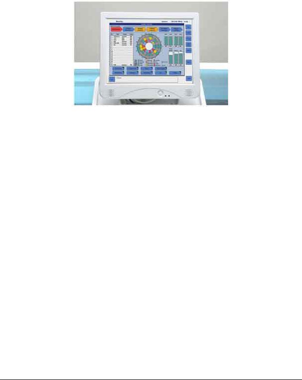
1.1.2.1 The Control Unit
The control unit of the e411 analyzer is a touchscreen, no-keyboard type computer, which is located on the left-center of the analyzer unit. This monitor unit contains the controlling software and also has an on-screen keyboard function.
Figure 1.1-5 Control unit
Version 1.0 – May 2006 |
1 - 2 |
Chapter 1.1 |

RD/Hitachi cobas e411 |
Service Manual |
1.1.2.2 The Analyzer Unit
Figure 1.1-6
The analyzer unit on the disk system consists of the:
•sample/reagent area
•consumables area
•measuring area
•operation switch
The only difference on the rack system is in the sample area. The sample disk is replaced by a rack sampling unit.
Refer to the photo below.
Figure 1.1-7
Version 1.0 – May 2006 |
1 - 3 |
Chapter 1.1 |

RD/Hitachi cobas e411 |
Service Manual |
1.1.2.3 Sample/Reagent Area
The sample/reagent area comprises the left half of the analyzer and consists of a sample disk or rack sampler (rack system), rack bar code reader (rack system), sample/reagent (S/R) probe, bar code reader, bar code card reading station, reagent disk, a cap open/close mechanism, a microparticle mixer, probe/ mixer rinse station and sample/reagent (S/R) pipettor.
The sample disk accommodates up to 30 samples. The A-Line of the rack sampler accommodates 75 samples on a single tray (15 racks at a time; each rack with five positions) and 25 samples in the input buffer for a total capacity of 100 samples. The reagent disk, temperature controlled at 20 ± 3 °C, accommodates up to 18 reagent packs.
1.1.2.4 Consumables Area
The consumables area is on the right of the analyzer, consisting of three tip trays, three AssayCup trays, a gripper unit, cup disposal opening, liquid waste container, solid waste tray and liner and system water container.
1.1.2.5 Measuring Area
The measuring area includes the incubator, the sipper probe, sipper rinse station, system reagents (ProCell and CleanCell), an aspiration station, sipper pipettor and the detection unit. The sipper probe aspirates the incubated reaction mixture into the detection unit for result determination.
1.1.2.6 Operation Switch
The operation ON/OFF switch is located on the front left of the analyzer. In addition, there is a circuit breaker for the analyzer located on the right side panel and a rack sampler circuit breaker located on the left side of the rack sampler.
Version 1.0 – May 2006 |
1 - 4 |
Chapter 1.1 |
RD/Hitachi cobas e411 |
Service Manual |
1.1.3 Control Unit Components
The control unit consists of a color touchscreen monitor, host interface and external printer.
1.1.3.1 Touchscreen Monitor
The touchscreen monitor is located on the left-center of the analyzer and displays the software. For details on the cobas e411 software, refer to the Software Guide.
Figure 1.1-8 Touchscreen monitor
Version 1.0 – May 2006 |
1 - 5 |
Chapter 1.1 |

RD/Hitachi cobas e411 |
Service Manual |
1.1.3.2 On-screen Keyboard
The e411 software has an on-screen keyboard. For details refer to the Software Guide.
Figure 1.1-9 On-screen keyboard
1.1.3.3 External Printer
The instrument uses an 80-column, graphics-capable, dot matrix printer.
The printer is connected to the analyzer via a USB port. The analyzer has two USB ports on its left side.
Figure 1.1-10 Location of the USB ports and Host port
1.1.3.4 Host Interface
The instrument can be bidirectionally interfaced with a host computer.
Please refer the Host Interface manual in detail.
Version 1.0 – May 2006 |
1 - 6 |
Chapter 1.1 |

RD/Hitachi cobas e411 |
Service Manual |
1.1.4 Sample/Reagent Area Components
The sample/reagent area consists of a sample disk or rack sampler (rack system), rack ID bar code reader (rack system), sample/reagent (S/R) probe, bar code reader, bar code card reading station, reagent disk, cap open/close mechanism, microparticle mixer, probe/mixer rinse station and sample/reagent (S/R) pipettor.
Figure 1.1-11 Sample Disk
The sample disk has 30 positions for samples, calibrators and controls. Patient samples may be placed in either primary sample tubes or sample cups. Built-in adapters allow intermixing of different size primary sample tubes.
Sample tubes that may be used are listed in chapter 2.7 Technical Data.
Sample cups [2 mL (Standard) Hitachi cups only] may be placed directly on the sample disk or on top of 16 mm primary sample tubes.
Figure 1.1-12 Sample disk
CAUTION
Micro cups cannot be used on the e411 analyzer!
Version 1.0 – May 2006 |
1 - 7 |
Chapter 1.1 |
RD/Hitachi cobas e411 |
Service Manual |
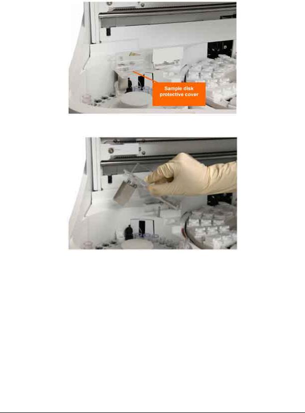
Note: How to raise the sample disk protective cover
To take out the sample disk, first you must raise the sample disk protective cover. The cover can be held at a certain angle. To lay the cover down, release the hold by raising the cover up to its limit angle. Be sure to lay it down before you start operation.
Figure 1.1-13 Sample disk protective cover
Figure 1.1-14 n Raising the sample disk protective cover
Version 1.0 – May 2006 |
1 - 8 |
Chapter 1.1 |
RD/Hitachi cobas e411 |
Service Manual |
|
|
|
|
|
|
|
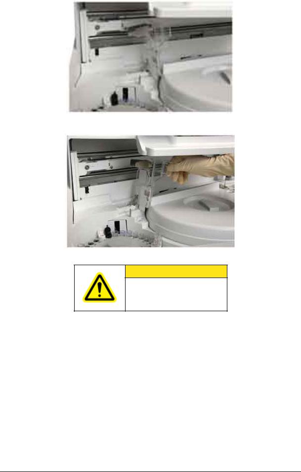
Figure 1.1-15 Standing angle
Figure 1.1-16 Limit angle
CAUTION
Be sure to lay down the sample disk protective cover before you start operation.
Version 1.0 – May 2006 |
1 - 9 |
Chapter 1.1 |
RD/Hitachi cobas e411 |
Service Manual |
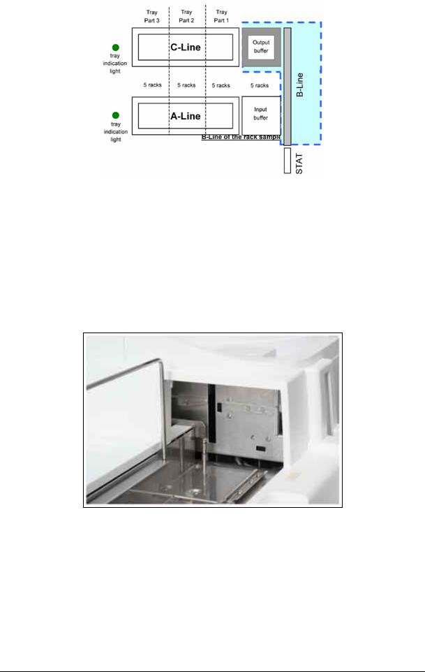
Figure 1.1-17
Rack Sampler
The rack sampler consists of an A-Line, B-Line, C-Line and STAT position.
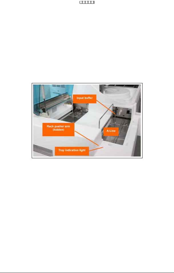
1.1.4.1 A-Line
Specimens are placed in 5-position sample racks and are loaded onto a tray. Once a tray is loaded, additional racks can be added to the tray one at a time during Operation, provided the tray indication light is green (ON). If the light is out (OFF), the pusher arm is preparing to move. The pusher arm is located at the far left of the A-Line and pushes the sample racks forward and onto the B-Line.
The A-Line holds a tray that accommodates 15 racks at one time. Another five racks can be in the input buffer. Therefore, you can have a total of 100 specimens loaded at any one time. Refer to the photo and graphic below.
Figure 1.1-18
Version 1.0 – May 2006 |
1 - 10 |
Chapter 1.1 |

RD/Hitachi cobas e411 |
Service Manual |
Figure 1.1-19
1.1.4.2 B-Line
The B-Line transports the sample racks, single file, first to the rack bar code reader. Here each position in the rack is scanned for a sample bar code. After the last position is scanned, the bar code reader scans the rack ID. After the last specimen is sampled, the rack is transferred via the output buffer onto the tray on the C-Line. Refer to the photo and graphic below.
Figure 1.1-20
Version 1.0 – May 2006 |
1 - 11 |
Chapter 1.1 |
RD/Hitachi cobas e411 |
Service Manual |
Figure 1.1-21 B-Line of the rack sampler
1.1.4.3 Rack Bar Code Reader
The rack bar code reader reads both sample bar code labels and the rack bar code label. The bar code reader is auto-discriminating, allowing the use of various types of bar codes during operation. Bar code symbologies read include:
•NW7 (Codabar)
•Code 39
•Code 128
•Interleaved 2 of 5
Figure 1.1-22 Rack bar code reader
Version 1.0 – May 2006 |
1 - 12 |
Chapter 1.1 |
RD/Hitachi cobas e411 |
Service Manual |
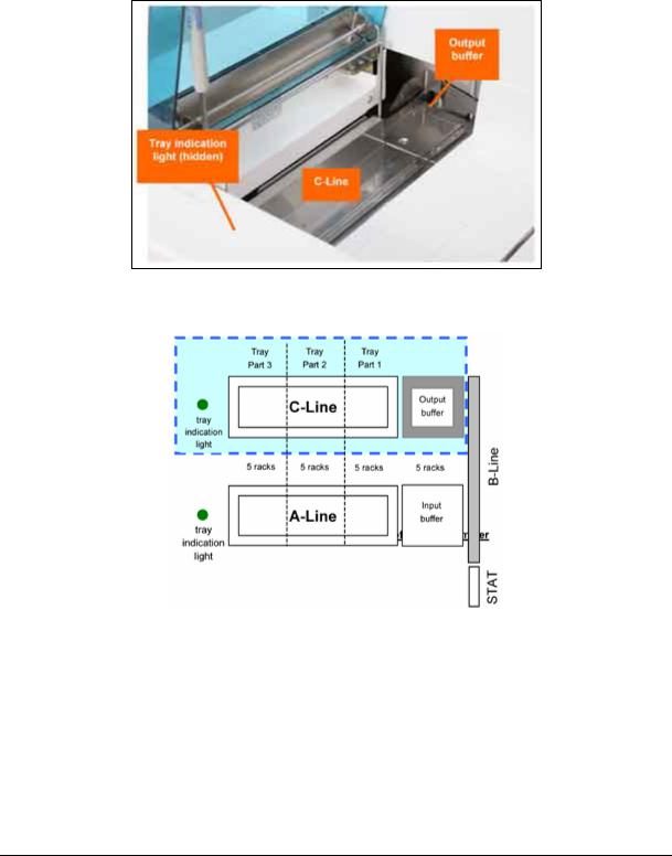
1.1.4.4 C-Line
Racks are off-loaded from the B-Line into the output buffer. If there is no tray, up to 5 racks can enter the output buffer, thereafter the sampling procedure is stopped. When the sixth rack is moved into the output buffer, a rack is pushed onto the tray on the C-Line. You can remove the tray from the C-Line any time the tray indication light is green (ON). If the light is out (OFF), the system is preparing to push a rack onto the C-Line tray. You cannot remove single racks from the C-Line. You must remove an entire tray at one time.
Figure 1.1-23
Figure 1.1-24 C-Line of the rack sampler
If the tray is removed, the system continues to push racks into the output buffer. If the buffer fills and there is no tray, the analyzer issues an alarm and stops sampling racks.
Version 1.0 – May 2006 |
1 - 13 |
Chapter 1.1 |

RD/Hitachi cobas e411 |
Service Manual |
|
|
|
|
|
|
|
Figure 1.1-25 Output buffer with racks
1.1.4.5 STAT Position
The STAT position is located at the front of the analyzer and is in line to feed directly onto the B-Line. Place a rack in the position as directed on the label and press the STAT key. When the rack currently being sampled is completed, the STAT rack is pushed onto the B-Line and is sent on to the rack bar code reader and sampling position.
Figure 1.1-26
Version 1.0 – May 2006 |
1 - 14 |
Chapter 1.1 |

RD/Hitachi cobas e411 |
Service Manual |
Figure 1.1-27 STAT position of the rack sampler
1.1.4.6 Sample Rack
Sample cups, primary sample tubes, calibrator or control vials are placed in sample racks shown below. Each sample rack holds a maximum of five samples. Each tube slot contains adapters that allow the rack to hold different sizes of primary sample tubes. Each rack has a unique ID found on the bar code label on the back end of the rack. This rack ID is read by the bar code reader and transferred to the system. This ID appears on the screens in the software and on the reports.
Figure 1.1-28 Sample rack
1.1.4.7 Sample/Reagent (S/R) Probe
The sample/reagent probe is located on the back left wall of the analyzer and is mounted on an arm (S/R arm) that moves horizontally between the sample and reagent disk. The probe uses disposable tips to avoid sample carryover, and has liquid level and clot detection for accurate pipetting. Liquid level detection is accomplished by capacitance measurement. Clot detection is accomplished by a pressure transducer.
A new AssayTip is utilized with every new pipetting sequence. For example, TSH = 1 tip for R1, R2 and sample, then one new tip for microparticles. The tip is washed externally at the rinse station between each aspiration. Additional tips are used for sample dilutions or pretreatment.
Version 1.0 – May 2006 |
1 - 15 |
Chapter 1.1 |
Loading...