

Page 1

cobas b 221 system
Service Manual
Page 2

COBAS, COBAS B and LIFE NEEDS ANSWERS
are trademarks of Roche.
©2009 Roche Diagnostics
Roche Diagnostics GmbH
D-68298 Mannheim
Germany
www.roche.com
Page 3

cobas b 221 system
Version History
Manual Version Software Version Version date Changes
1.0 1.0 May 2003 First edition
2.0 2.0 March 2004 Chapter 2, 3, 4, 5, 6, 7, 8, 9
3.0 3.01 June 2004 Chapter 2, 3, 4, 6, 8, 9
4.0 4.00 December 2004 Chapter 1, 2, 3, 6, 7, 8, 9
4.1 4.02 July 2005 All chapters
5.0 5.00 November 2005 Parts A, B, D, E, G
6.0 5.00 March 2006 All chapters
7.0 6.00 December 2006 All chapters
8.0 7.00 December 2007 All chapters
9.0 n./a. May 2009 Chapter 2, 3, 6, 7
Language Order Number
English 03309614001
Edition notice
cobas b 221 system
Service Manual
cobas b 221 system In the course of 2006 the Roche OMNI S system was rebranded under the Roche
e
For more information, see:
Software on page G-5
Service Manual on page G-6
This manual is for the maintenance and repair of the cobas b 221 system.
Diagnostics professional IVD user brand cobas®.
Systems with a serial number of 5001 or above are cobas b 221 systems.
Systems with a serial number up to 5000 are Roche OMNI S systems.
Every effort has been made to ensure that all the information contained in this
manual is correct at the time of printing. However, Roche Diagnostics GmbH reserves
the right to make any changes necessary without notice as part of ongoing product
development.
Any customer modification to the instrument will render the warranty or service
agreement null and void.
Software updates are done by Roche Service representatives.
Roche Diagnostics May 2009
Service Manual · Version 9.0 3
Page 4

Intended use
cobas b 221 system
This manual contains all of the information required for the maintenance and repair
of the cobas b 221 system.
The user must be familiar with the function and operation of the instrument to fully
understand the processes described here.
e
For more information about cobas b 221 system instructions, refer to:
cobas b 221 system Instructions for Use
cobas b 221 system Reference Manual
Observe the service and repair procedures described in this manual and use only
genuine Roche replacement parts and Roche-approved materials to guarantee the full
functionality of the cobas b 221 system.
e
For the order numbers of replacement parts, refer to the cobas b 221 system Spare Part
List.
e
For an overview of possible revisions and available software versions, see:
Software on page G-5
Service Manual on page G-6
Copyrights
Trademarks
Contact address
Manufacturer
© 2009 Roche Diagnostics GmbH, All rights reserved.
The contents of this document may not be reproduced in any form or communicated
to any third party without the prior written consent of Roche Diagnostics. Every
effort is made to ensure its correctness. Subject to change without notice.
COBAS, COBAS B, LIFE NEEDS ANSWERS, ROCHE OMNI, AUTOQC,
ROCHE MICROSAMPLER, COMBITROL, AUTO-TROL and COBAS BGE LINK
are trademarks of Roche.
Roche Diagnostics GmbH
D-68298 Mannheim / Germany
www.roche.com
Roche Diagnostics May 2009
4 Service Manual · Version 9.0
Page 5

cobas b 221 system
Table of contents
Ver si on Hi st or y 3
Edition notice 3
Intended use 4
Copyrights 4
Trademarks 4
Contact address 4
Preface 7
How to Use This Manual 7
Where to Find Information 7
Conventions used in this manual 8
System Description Part A
1 Safety information
Important information A-5
Operating safety information A-6
Important notes and warnings A-6
Disinfectants A-7
ESD protection measures A-8
2 Fluid actions
Fluid actions overview A-13
Pin assignment of S2 and S3 Fluid Packs A-19
T&D positions A-20
Measurement A-21
Calibration A-31
Servicing Part B
3 Protected software functions
Protected setup B-5
Protected system functions B-11
Protected infos B-12
Protected DB functions B-13
4 Components
Important notes B-19
Shutdown B-19
Removing the rear panel B-20
Folding up the central measuring unit B-20
T&D system (Turn & Dock) B-21
Fluid mixing system (FMS) B-33
Sample distributor (SD) B-35
BG measuring chamber B-40
ISE measuring chamber (cobas b 221<3>–<6>
systems only) B-42
MSS measuring chamber (cobas b 221<5/6> systems
only) B-44
Measuring chamber cartridge B-48
COOX module (cobas b 221<2/4/6> systems only)
B-51
tHb/SO
module (cobas b 221<1/3/5> systems only)
2
B-62
Peristaltic pumps (PP) B-64
Bottle compartment B-67
Vacuum system B-73
Valve s B -8 1
Mainboard unit B-89
Interface unit B-91
Touch screen/PC unit B-95
Printer B-108
Fan unit B-110
Replacing the valve bus cable B-110
Replacing the actuator bus main controller cable
B-112
Barcode scanner B-113
5 AutoQC module
AutoQC preparation for maintenance B-119
Initial installation of the AutoQC module B-119
Replacing the AutoQC module B-120
Replacing the AQC snap lock B-122
Replacing the AQC magnetic valve B-123
Replacing the AQC board B-124
Replacing the YZ distributor board B-125
Replacing the Z distributor board B-126
Replacing the flex cable (short) B-127
Replacing the flex cable (long) B-128
AQC sample tube B-129
Replacing the X motor B-131
Replacing the Y motor B-132
Replacing the Z motor B-132
Replacing the AutoQC steel tube B-133
Replacing the AQC temperature sensor B-134
Replacing the wash port B-135
Replacing the toothed belt (short) B-136
Replacing the toothed belt (long) B-137
Maintenance Part C
6 Maintenance
Decontamination C-5
cobas b 221<1/3/5> systems (tHb/SO2) C-10
cobas b 221<2/4/6> systems (COOX) C-12
AutoQC module C-14
Troubleshooting Part D
7 Troubleshooting
Important Notes D-11
Roche Diagnostics May 2009
Service Manual · Version 9.0 5
Page 6

General information D-11
System stops D-13
Module stops D-37
System warnings D-51
Valu e f l ag s D- 5 8
USB troubleshooting D-91
Touch screen/PC unit troubleshooting D-91
Important test routines D-95
Sensor limits (Sensor report) D-135
Glossary Part E
Glossary E-3
Index Part F
Index F-3
cobas b 221 system
Versions Part G
8 Versions
Software G-5
Service Manual G-6
Roche Diagnostics May 2009
6 Service Manual · Version 9.0
Page 7

cobas b 221 system
Preface
This manual contains all of the information required for the maintenance and repair
of the cobas b 221 system.
The user must be familiar with the function and operation of the instrument to fully
understand the processes described here.
e
For more information about cobas b 221 system instructions, refer to:
cobas b 221 system Instructions for Use
cobas b 221 system Reference Manual
Observe the service and repair procedures described in this manual and use only
genuine Roche replacement parts and Roche-approved materials to guarantee the full
functionality of the cobas b 221 system.
e
For the order numbers of replacement parts, refer to the cobas b 221 system Spare Part
List.
e
For an overview of possible revisions and available software versions, see:
Software on page G-5
Service Manual on page G-6
How to Use This Manual
o
Keep this manual in a safe place to ensure that it is not damaged and remains available for use.
o
This Service Manual should be easily accessible at all times.
To help finding information quickly, there is a table of contents at the beginning of
the book and each chapter. In addition, a complete index can be found at the end.
Where to Find Information
In addition to the Service Manual, the following documents are also provided to assist
in finding desired information quickly:
o cobas b 221 system Instructions for Use
o cobas b 221 system Operator’s CD
o cobas b 221 system Reference Manual
o cobas b 221 system Short Instruction
o cobas b 221 system Service Manual (PDF or iSDoc version in GRIPS)
o cobas b 221 system Spare Part List (PDF or iSDoc version in GRIPS)
Roche Diagnostics May 2009
Service Manual · Version 9.0 7
Page 8
Conventions used in this manual
Visual cues are used to help locate and interpret information in this manual quickly.
This section explains formatting conventions used in this manual.
Symbols The following symbols are used:
Symbol Used for
a Procedural step
o List item
e
h Call up of screen
Cross-reference
Note All sections or text locations marked with
Caution / Warning All sections / passages that are marked with this
Biohazard Risk of infection!
cobas b 221 system
"NOTE" describe safe procedures that are
intended to provide the user with additional help.
symbol describe procedures and/or indicate
conditions or dangers that could damage or lead
to a malfunction in the cobas b 221 system, and
which therefore should never be attempted to
avoid potential injuries (to patients, users and
third parties).
High Voltage Passages that are marked with this symbol warn
of an immediate danger in connection with
electrical wiring or components.
ESD protection measures All sections or passages that are marked with this
symbol warn of specific dangers in connection
with static discharge. Packages that are marked
with this symbol must only be opened by trained
technical staff.
Invisible Laser Radiation Avoid direct radiation to eyes
Laser Class 3R according to EN 60825-1
P0 < 5 mW
λ = 635 - 850 nm
e
For more information about warning symbols, refer to the cobas b 221 system Intructions
for Use.
e
For more information about ESD protection measures, see ESD protection measures on
page A-8.
Roche Diagnostics May 2009
8 Service Manual · Version 9.0
Page 9

cobas b 221 system
Abbreviations The following abbreviations are used:
Abbreviation Definition
A
ADC Analogue to digital converter
ANSI American National Standards Institute
AQC AutoQC
B
BG Blood Gases
C
CCD Charge coupled device
CMOS Complementary Metal-Oxide Semiconductor
E
EEPROM Electrically erasable programmable read-only memory
e.g. exempli gratia – for example
EC European community
EN European standard
ESD Electro Static Discharge
F
FMS Fluid Mixing System
FTP File Transfer Protocol
H
HIV Human Immunodeficiency Virus
HW Hardware
I
IEC International Electrical Commission
IfS Interference sensor (part of the MSS cartridge)
ISE Ion selective electrode
IVD In vitro Diagnostics
L
LCD Liquid Cristal Display
M
MC Measuring chamber
MOS Metal-Oxide Semiconductor
MSDS Material safety data sheet
MSS Metabolite Sensitive Sensor
Q
QC Quality control
R
REF Reference solution for ISE module
S
S1 S1 Rinse Solution
S2 S2 Fluid Pack
S3 S3 Fluid Pack A
Roche Diagnostics May 2009
Service Manual · Version 9.0 9
Page 10

Abbreviation Definition
SCD Sample container detection
SD Sample distributor
SIP Sample inlet path
SW Software
T
T&D Turn and Dock
TTL Transisitor-Transistor Logic
U
USB Universal Serial Bus
V
V19 Valve 19
VM FMS Mixing Valve
VPP (=VPS) Vacuum pump protector
cobas b 221 system
Roche Diagnostics May 2009
10 Service Manual · Version 9.0
Page 11

System Description
1 Safety information . . . . . . . . . . . . . . . . . . . . . . . . . . . . . . . . . . . A-3
2 Fluid actions . . . . . . . . . . . . . . . . . . . . . . . . . . . . . . . . . . . . . . . A-11
A
May 2009
Page 12

Page 13

cobas b 221 system 1 Safety information
Tab le of co nt ent s
Safety information
Before the maintenance and repair of the cobas b 221 system, it is essential that the
warnings, cautions, and safety requirements contained in this manual are read and
understood by the user.
In this chapter
Important information ................................................................................................... 5
Operating safety information ......................................................................................... 6
Important notes and warnings ....................................................................................... 6
Disinfectants .................................................................................................................... 7
Deproteinizer .............................................................................................................7
Other disinfectants .................................................................................................... 7
ESD protection measures ................................................................................................ 8
Explanation of the phenomenon .............................................................................. 8
Influence of electrostatic charges on components ................................................... 8
Why is ESD protection so important today? ............................................................9
How can ESD protection be guaranteed? .................................................................9
Conclusion .................................................................................................................9
Chapter
1
Roche Diagnostics May 2009
Service Manual · Version 9.0 A-3
Page 14

1 Safety information cobas b 221 system
Tab le of co nt ent s
Roche Diagnostics May 2009
A-4 Service Manual · Version 9.0
Page 15

cobas b 221 system 1 Safety information
Important information
Important information
This Service Manual contains vital warning and safety information.
This instrument is only intended for one area of application which is described in the
instructions. The most important prerequisites for use, operation, and safety are
explained to ensure smooth operation. No warranty or liability claims will be covered
if the instrument is used in ways other than those described or if the necessary
prerequisites and safety measures are not observed.
The instrument may be operated only by persons whose qualifications enable them to
comply with the safety measures that are necessary during operation of the
instrument.
To avoid direct contact with biological materials, always wear appropriate protective
equipment such as lab clothing, protective gloves, safety glasses and, if necessary, a
face mask. Additionally a face shield must be worn if there is a potential of a
splashback. Appropriate disinfection and sterilization procedures must be followed.
To avoid direct contact with biological materials, wear lab clothing, protective gloves,
protective glasses and, if necessary, mouth cover and apply disinfection and
sterilization procedures.
Explanation
Adjustments and maintenance performed with removed covers and connected power
may be attempted only by a qualified technician who is aware of the associated
dangers.
Instrument repairs are only to be performed by the manufacturer or qualified service
personnel.
Only accessories and supplies either delivered by or approved by Roche are to be used
with the instrument. This ensures the performance and measuring accuracy of the
unit. These items are manufactured especially for use with this instrument and meet
the highest quality requirements.
Operation of the instrument with solutions whose composition is not consistent with
that of the original solutions' can negatively affect, above all, the long-term
measurement accuracy. Deviations in the composition of the solutions can also
decrease the service life of the electrodes.
The quality control requirements must be completed at least once daily for safety
reasons. Because the measurement results delivered by the instrument depend not
only on the instrument's proper operation but also on a variety of external influences
(for example: preanalytics), the results produced by this instrument should be
appraised by an expert before additional measures are taken based on the results.
Meaning: Important, see the cobas b 221 system Instructions for Use.
Roche Diagnostics May 2009
Service Manual · Version 9.0 A-5
Page 16
1 Safety information cobas b 221 system
Operating safety information
Operating safety information
The instrument has been constructed and tested according to the following
European Standards:
o IEC/EN 61010-1
o IEC/EN 61010-2-101
o IEC/EN 61010-2-081 + A1
It was delivered from the factory in flawless condition with regards to safety features.
In order to preserve this condition and ensure safe operation, the user must respect
the notices and warnings that are contained in this Service manual.
o This equipment is a Class I laser product, and it complies with FDA Radiation
Performance Standards, 21 CFR Subchapter J (only valid for cobas b 221<1/3/5>
systems with tHb/SO
o This instrument is classified under the protection class I according to
IEC/EN 61010-1.
o The instrument meets the conditions for overvoltage category II.
o The instrument meets the conditions for contamination level 2.
o Do not operate the instrument in an explosive environment or in the vicinity of
explosive anesthetic mixtures containing oxygen or nitrous oxide.
o If objects or liquids enter the internal areas of the instrument, remove the
instrument from its power supply and allow an expert to check it thoroughly
before using it again.
o The instrument is suitable for long-term operation indoors.
module).
2
o
The power cord may be plugged only into a grounded socket. When using an extension cord,
make sure it is properly grounded.
o
Any rupture of the ground lead inside or outside the instrument or a loose ground connection
can render hazardous operation of the instrument. Intentional disconnection of the grounding
is not permitted.
o
The instrument is not suitable for operation with a direct current power supply. Use only the
original mains plug delivered with the cobas b 221 system.
o
The use of controls or adjustments or performance of procedures other than those specified
herein may result in hazardous radiation exposure.
Important notes and warnings
o
Never operate the analyzer in the vicinity of volatile or explosive gases
(e.g. anesthetic gases, etc.)!
o
The instrument must be connected to a 2-pin, grounded socket.
o
The power cable and the plug must be undamaged. Damaged power cables and plugs must be
replaced immediately.
o
Before opening the back panel switch off the instrument and disconnect the power cable.
o
Replace damaged fuses with the specified type of fuse.
Roche Diagnostics May 2009
A-6 Service Manual · Version 9.0
Page 17
cobas b 221 system 1 Safety information
Disinfectants
o
Service and repair work must be done only as specified in this manual. Unqualified service or
repair work may result in warranty claims not being granted.
o
Use only suitable tools and test instruments for service and repair work.
o
Do not allow fluids to enter the interior of the instrument, because this may damage the
electronics.
o
Use only slightly moistened cloths or cotton sticks to clean the instrument.
Disinfectants
Use only liquid disinfectant such as protein remover (Roche deproteinizer) or an alcohol-based
(about 70%) surface disinfectant.
Do not spray disinfectant directly onto the instrument because this could cause malfunctions in the
electronics.
Do not use any type of bleaching agent. Exception: Roche Deproteinizer.
Deproteinizer
Composition Aqueous NaOCl solution with active chlorine (≤ 2%)
Hazards identification Due to the basic and oxidizing character of the reagent ("Deproteinizer") local
First aid measures
Other disinfectants
Do not attempt to clean/decontaminate any part of the instrument before shutting it down and
unplugging it from the power source.
Before plugging in the instrument again and switching it on always wait for 15 minutes to allow the
disinfectant to evaporate.
irritations after contact with eyes, skin or mucous membranes cannot be excluded.
After inhalation:
After skin contact:
After eye contact:
After drinking:
breath fresh air, drink large amounts of water
wash with generous amounts of water, remove contaminated clothing
rinse eyes with generous amounts of water, contact an eye specialist
drink large amounts of water, avoid vomiting, contact a doctor
Use standard alcohol-based (70%) disinfectants to clean the surface of the
instrument. Read the product information first.
Never use standard disinfectant to clean the tubes and tubing paths under any circumstances!
Do not use any type of bleaching agent. Exception: Roche Deproteinizer.
Roche Diagnostics May 2009
Service Manual · Version 9.0 A-7
Page 18
1 Safety information cobas b 221 system
ESD protection measures
ESD protection measures
ESD = Electrostatic Sensitive Device
Explanation of the phenomenon
The most frequent cause of electrostatic discharge is friction of various materials such
as plastic, synthetic fiber, hard rubber or paper.
It can also be caused by bending or applying pressure to a material.
Discharges that are dangerous to components occur when "charged" bodies or
components do not have a discharge connection (ground) to discharge the
electrostatic charge.
The discharges normally do not have a high capacity, but there are often voltage
differences in the range of several thousand volts. The discharges are perceived as
small shocks or visible sparks.
Examples: o Shoes with rubber soles:
Friction is caused by walking. A person develops an electrical charge different
from the ground. A discharge occurs when an object (e.g. door handle) is
contacted.
o Synthetic fiber clothing:
Discharge is audible and is visible in darkness.
The dryer the air the greater the risk of electrical discharge caused by friction.
Eectrostatic charges are less likely to build up in humid air, particularly when saturated with water
vapor.
The probability of ESD phenomena is therefore particularly great in a northern hemisphere winter
in centrally heated rooms where the humidity is low.
Influence of electrostatic charges on components
If a person with an electrostatic charge touches a component, a discharge over a
connection of an IC or semiconductor element may occur. The resulting voltages may
damage the component.
Critical situations can occur while repairing or testing components if they are lying
on a more or less conductive surface (e.g. table top) and a person with an electrostatic
charge touches them. A discharge through a critical component connection can also
occur in this case.
Roche Diagnostics May 2009
A-8 Service Manual · Version 9.0
Page 19

cobas b 221 system 1 Safety information
ESD protection measures
Why is ESD protection so important today?
Formerly, current controlling semiconductors were mostly used (TTL, normal
transistors, etc.).
Today the principle of current logic is virtually the only technology in use in MOS
and CMOS components.
Currents generated by an electrostatic discharge (as much as several kV!) destroy the
sensitive component inputs or cause hidden damage. This damage is generally not
immediately detectable.
Another effect is that the clearances inside the ICs continuously become smaller. The
internal wires become thinner and thinner, the allowable maximum input voltages
become smaller and the effects of any discharges become more and more critical.
How can ESD protection be guaranteed?
A continuous discharge is required when working on an electronic assembly. Do this
as follows:
o Use ESD wrist bands (special wrist bands connected to a protective ground).
o Repairs and tests on assemblies must only be conducted on tables with ESD mats
connected to grounds or ESD wrist bands.
o Always pick up components at the edge (e.g. like a photo).
o Components must always be transported in ESD packages or appropriate storage
or shipping containers (use original packaging!).
o Shoes with rubber soles or clothing of synthetic fibers must not be worn in
workshops where electronic components are repaired.
o Use a humidifier if necessary to maintain optimum humidity in the work area.
o Do not touch assemblies or components with the hand after testing.
o Always transport and ship assemblies or components for repair in ESD protective
packaging only. This will prevent further damage that may result in
misinterpretation of the original cause of the fault.
The ESD mat consists of materials that have a very low, defined conductivity (1012 ohms).
The following materials prevent charges caused by friction from building up and protect the
component from damage.
o
ESD mats
o
ESD packages
o
Shipping containers
Conclusion
Of course, not all circuit boards and electronic assemblies require such careful
handling. An electrical board that only carries simple plug connectors does not
require ESD packaging.
In cases of doubt always use ESD packaging.
Roche Diagnostics May 2009
Service Manual · Version 9.0 A-9
Page 20

1 Safety information cobas b 221 system
ESD protection measures
Roche Diagnostics May 2009
A-10 Service Manual · Version 9.0
Page 21

cobas b 221 system 2 Fluid actions
Tab le of co nt ent s
Fluid actions
This chapter provides information about the fluidic actions of the cobas b 221 system.
In this chapter
Fluid actions overview ..................................................................................................13
cobas b 221<1> system ...........................................................................................13
cobas b 221<2> system ...........................................................................................14
cobas b 221<3> system ...........................................................................................15
cobas b 221<4> system ...........................................................................................16
cobas b 221<5> system ...........................................................................................17
cobas b 221<6> system ...........................................................................................18
Pin assignment of S2 and S3 Fluid Packs ..................................................................... 19
S2 Fluid Pack ............................................................................................................19
S3 Fluid Pack A (cobas b 221<5/6> systems only) ................................................ 19
T&D positions ...............................................................................................................20
Measurement .................................................................................................................21
Sample input ............................................................................................................ 21
Sample distribution ................................................................................................. 23
Aspirating MSS standby solution and starting FMS .............................................25
Washing the measuring chamber vicinity ..............................................................27
Wash i ng t Hb/ SO
Recalibrating BG/ISE and drying tHb/SO
Calibration .....................................................................................................................31
BG/ISE cleaning ....................................................................................................... 31
Calibrating the conductivity for CAL A or CAL B ................................................32
O
zero point calibration ........................................................................................34
2
Na conditioning .......................................................................................................35
Mix1/Mix2 calibration, aspirating BG/ISE reference solution .............................36
O2-air calibration .................................................................................................... 38
Aspirating MSS reference solution, calibration with standby solution ................ 39
CAL 1 Calibration ...................................................................................................41
or COOX and preparing Mix1 .................................................28
2
or COOX ...........................................29
2
Chapter
2
Roche Diagnostics May 2009
Service Manual · Version 9.0 A-11
Page 22

2 Fluid actions cobas b 221 system
Tab le of co nt ent s
CAL 2/CAL 3/CAL 4 Calibration ........................................................................... 42
COOX calibration ...................................................................................................43
Roche Diagnostics May 2009
A-12 Service Manual · Version 9.0
Page 23
cobas b 221 system 2 Fluid actions
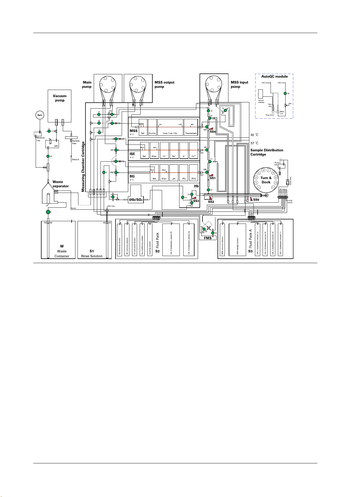
Fluid actions overview
Fluid actions overview
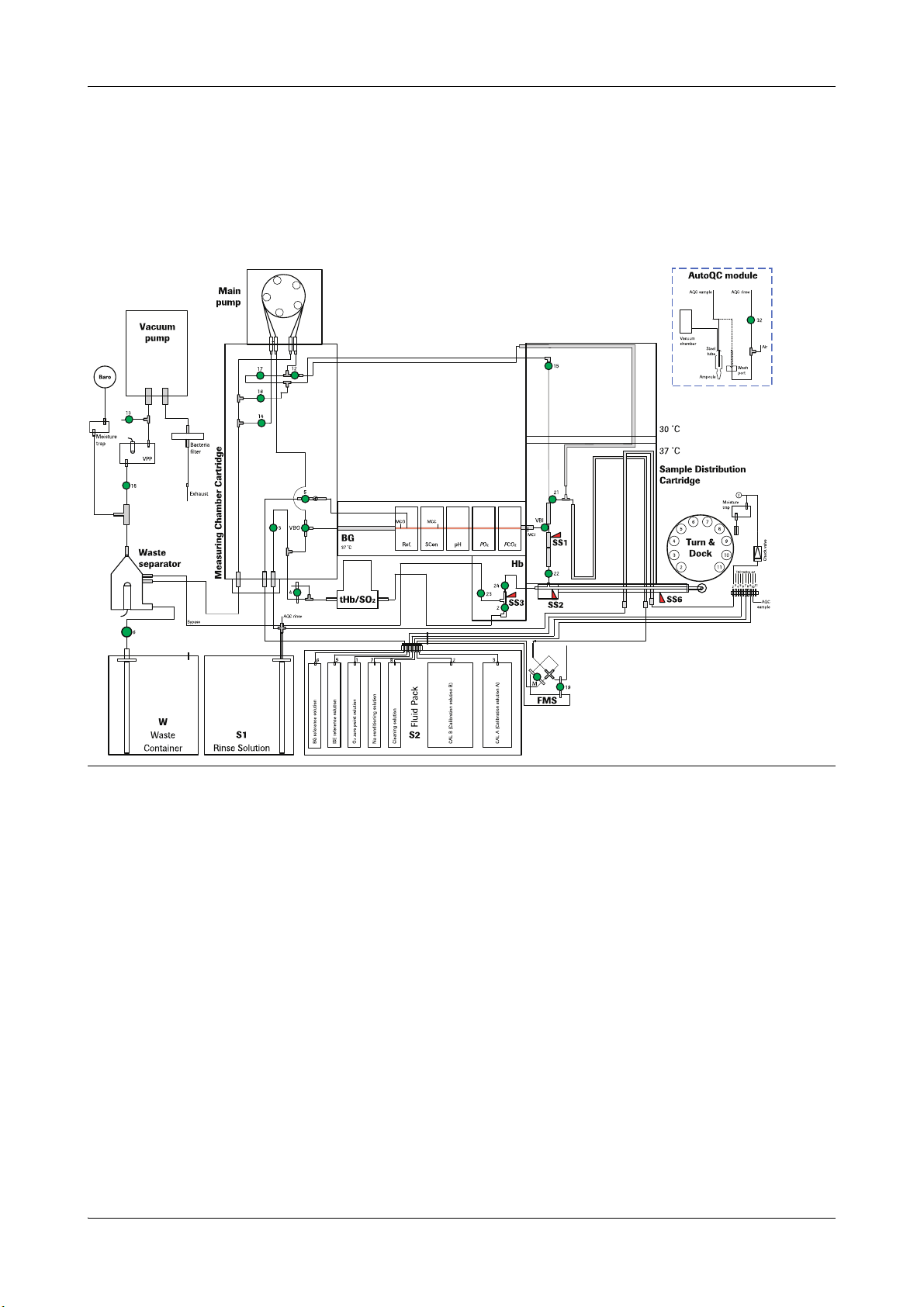
cobas b 221<1> system
Figure A-1 cobas b 221<1> system
Roche Diagnostics May 2009
Service Manual · Version 9.0 A-13
Page 24
2 Fluid actions cobas b 221 system
Fluid actions overview
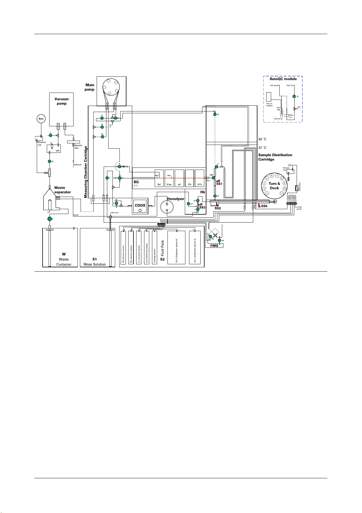
cobas b 221<2> system
Figure A-2 cobas b 221<2> system
Roche Diagnostics May 2009
A-14 Service Manual · Version 9.0
Page 25
cobas b 221 system 2 Fluid actions
Fluid actions overview
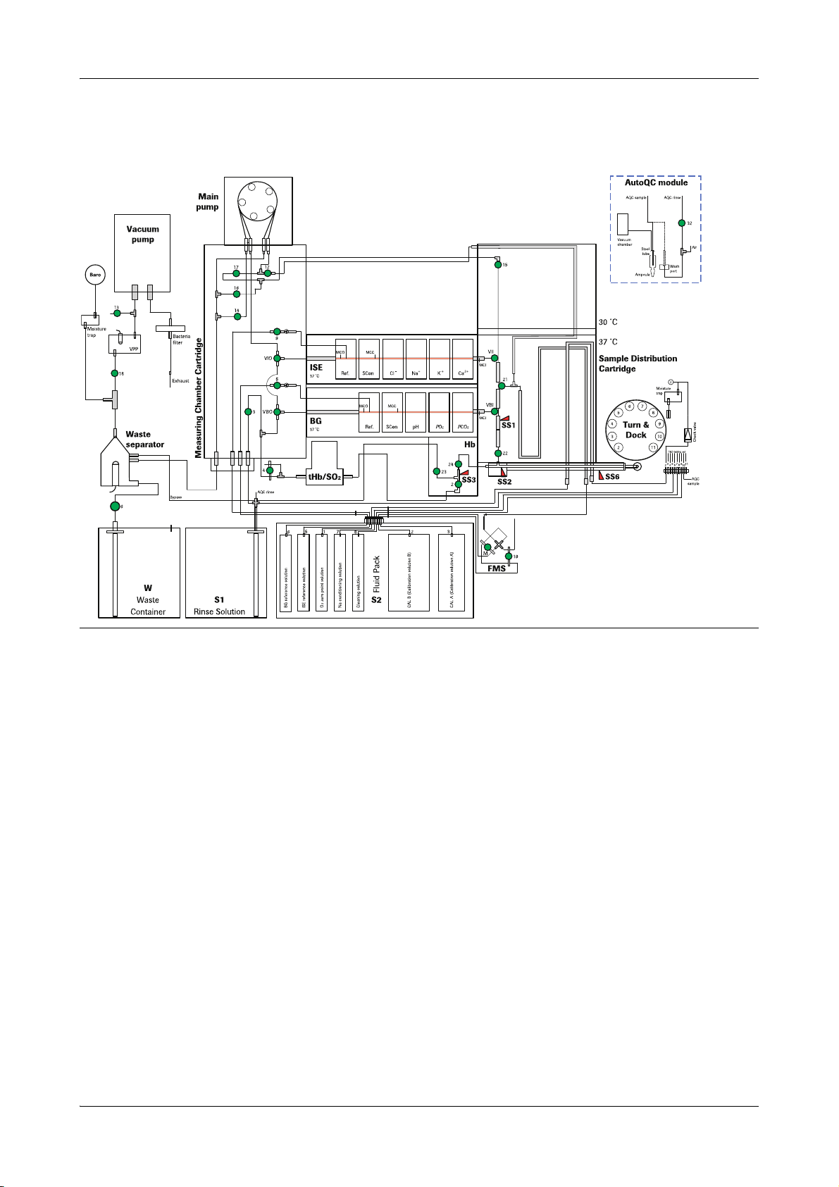
cobas b 221<3> system
Figure A-3 cobas b 221<3> system
Roche Diagnostics May 2009
Service Manual · Version 9.0 A-15
Page 26
2 Fluid actions cobas b 221 system
Fluid actions overview
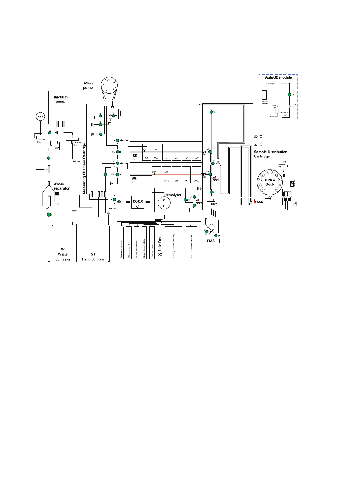
cobas b 221<4> system
Figure A-4 cobas b 221<4> system
Roche Diagnostics May 2009
A-16 Service Manual · Version 9.0
Page 27
cobas b 221 system 2 Fluid actions
Fluid actions overview
cobas b 221<5> system
Figure A-5 cobas b 221<5> system
Roche Diagnostics May 2009
Service Manual · Version 9.0 A-17
Page 28

2 Fluid actions cobas b 221 system
Fluid actions overview
cobas b 221<6> system
Figure A-6 cobas b 221<6> system
Roche Diagnostics May 2009
A-18 Service Manual · Version 9.0
Page 29
cobas b 221 system 2 Fluid actions
C
D
F
E
B
A
G
H
C
D
F
E
B
A
G
H
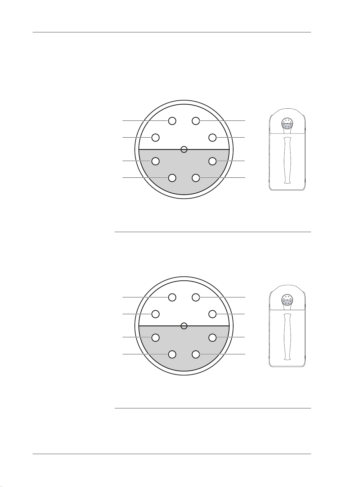
Pin assignment of S2 and S3 Fluid Packs
Pin assignment of S2 and S3 Fluid Packs
S2 Fluid Pack
A O2 zero point solution
B CAL B (calibration solution)
C CAL A (calibration solution)
D empty
Figure A-7 Pin assignment of S2 Fluid Pack
S3 Fluid Pack A (cobas b 221<5/6> systems only)
E ISE reference solution
F BG reference solution
G Na conditioning solution
H Cleaning solution
A CAL 2 (calibration solution 2)
B MSS standby solution
C CAL 1 (calibration solution 1)
Roche Diagnostics May 2009
Service Manual · Version 9.0 A-19
D empty
Figure A-8 Pin assignment of S3 Fluid Pack A
E empty
F MSS reference solution
G CAL 4 (calibration solution 4)
H CAL 3 (calibration solution 3)
Page 30
2 Fluid actions cobas b 221 system
D
C
A
B
E
F
I
J
K
H
G
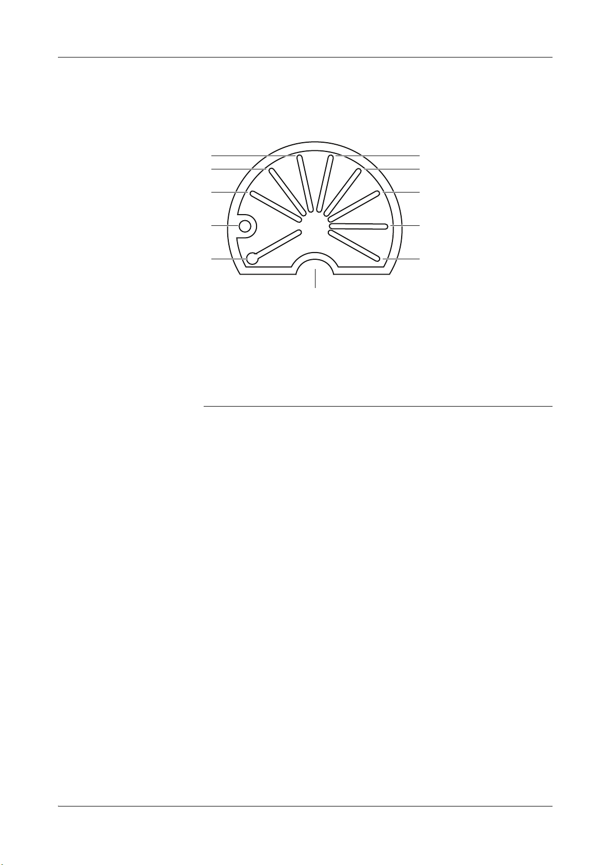
T&D positions
T&D positions
A 1: Releases the fill port for placing a sample
B 2: S1 Rinse Solution
C 3: Position for "aspiration from the syringe“
D 4: Dock position
E 5: O
F 6: CAL 2 from S3 Fluid Pack A
Figure A-9 T&D positions
zero point solution from S2 Fluid Pack
2
(cobas b 221<5/6> systems only)
G 7: Na conditioning solution from S2 Fluid
Pack
H 8: CAL 3 from S3 Fluid Pack A
(cobas b 221<5/6> systems only)
I 9: Cleaning solution from S2 Fluid Pack
J 10: AutoQC connection
K 11: CAL 4 from S3 Fluid Pack A
(cobas b 221<5/6> systems only)
Roche Diagnostics May 2009
A-20 Service Manual · Version 9.0
Page 31

cobas b 221 system 2 Fluid actions
A
B C D E F G
Measurement
Measurement
Sample input
Injecting sample
A V24
B Waste separator
Figure A-10 Injecting sample
C V23
D SS3
Sample path: o fill port >
E SS2
F SS6
G Fill port
The sample container is detected by a light barrier on the T&D module.
o sample inlet path >
o SS2
o When the sample has reached SS2 the user is prompted (by beeping and prompt
window) to remove the sample container.
Roche Diagnostics May 2009
Service Manual · Version 9.0 A-21
Page 32

2 Fluid actions cobas b 221 system
A
B
C
Measurement
Excess sample material: o V24 (open) >
o V23 (open) >
o Bypass >
o Waste separator
Aspirate sample
A Main pump
B SS2
Figure A-11 Aspirate sample
Sample path: o fill port >
C Fill port
The sample container is detected by a light barrier on the T&D module. The sample is
aspirated through the cross channel with the main pump.
o sample inlet path >
o SS2
o When the sample has reached SS2 the user is prompted (by beeping and prompt
window) to remove the sample container.
Roche Diagnostics May 2009
A-22 Service Manual · Version 9.0
Page 33

cobas b 221 system 2 Fluid actions
C
A
B
DEF
G
F
LKJ
H/I
I
Measurement
Sample distribution
A Waste separator
B Wash rail
C Main pump
D MSS output pump
E Position MSS
F Position ISE
G Separate MSS
Figure A-12 Sample distribution
H Separate BG
I Position BG, separate ISE
J Separate tHb/SO
K Position tHb/SO2 or COOX
L S1 Rinse solution
When the sample is detected by SS2 the sample distribution is started. The sequence
of the individual aspiration phases depends on the existing or requested modules.
or COOX
2
Separating BG: The start of the sample is aspirated from SS2 to SS1. The volume SS2-SS1 is specified
for filling the BG measuring chamber.
Separating tHb/SO
or COOX: One sample segment is aspirated from SS2 to SS3. The volume SS2-SS3 is specified for
2
filling the tHb/SO2 or COOX module.The user can specify in the setup whether
tHb/SO2 / COOX or ISE is separated first.
Roche Diagnostics May 2009
Service Manual · Version 9.0 A-23
Page 34

2 Fluid actions cobas b 221 system
Measurement
Positioning BG and
separating ISE:
This aspiration process assumes that the sample column tip is at SS1. It is aspirated
via VBI and VBO with the main pump. The start of the sample movement is detected
by the conductivity (breaking of the calibration solution column in the measuring
chamber). If this does not occur at the right time, an aspiration error is displayed. The
positioning of the sample is controlled by the MCI-MCO contact path. If a timeout
occurs because an excessively low signal or a non-reproducible conductivity signal, an
aspiration error is displayed. During the aspiration the sample is "observed" with SS1;
if the volume of the sample is too small, this interferes with the aspiration process.
After closing the VBI the ratio of the conductivities of MCI-MCO to MCI-MCC is
checked. If there are air bubbles in the MCI-MCO area, this can result is the
aspiration process restarting and the VBI opening again. When the corresponding
conductivity level is reached, the positioning of the sample is complete.
During the BG positioning ISE is separated between SS2 and SS1.
Positioning ISE: This aspiration process is similar to positioning BG. If an ISE measurement is not
required, the remainder of the sample is aspirated to VII through the sample
distributor to establish the required initial state for a subsequent MSS positioning.
Separating MSS and
A sample segment is aspirated to the SS4.
washing rail:
Positioning MSS: The sample is aspirated by turning the MSS output pump and opening the VSI. The
tearing of the standby solution and the start of the sample is detected by the
conductivity at the MSS input. Then it must also be possible to detect the tearing of
the standby solution and the sample start, at which the MSS output pump is stopped.
The completed sample positioning is checked again for freedom from bubbles via the
conductivity distances.
Positioning tHb/SO
or COOX: The sample segment for measurement of tHb/SO2 or COOX is positioned last. The
2
valves V2, V4, V17 and V16 are opened and aspirated with the main pump. The
sample is still hemolyzed in the event of a COOX measurement.
Roche Diagnostics May 2009
A-24 Service Manual · Version 9.0
Page 35

cobas b 221 system 2 Fluid actions
ABC
G
F
E
D
Measurement
Aspirating MSS standby solution and starting FMS
A MSS output pump
B MSS input pump
C Aspirating MSS standby solution
D CAL B
Figure A-13 Aspirating MSS standby solution and starting FMS
The MSS is positioned in four subsections:
Preconditioning by aspiration of
standby solution (1)
This process is done before aspiration of the sample. A little reference solution is
aspirated via V8 and the MSS reference electrode and is checked with the conductivity
section at the MSS output.
e
For more information, see Aspirating MSS reference solution, calibration with standby
solution on page A-39.
Then the measuring chamber is filled with standby solution.
E CAL A
F Starting FMS
G MSS standby solution
Roche Diagnostics May 2009
Service Manual · Version 9.0 A-25
Page 36

2 Fluid actions cobas b 221 system
Measurement
Aspirate sample The sample is aspirated by turning the MSS output pump and opening the VSI.
e
For more information, see Sample distribution on page A-23.
The tearing of the standby solution and the start of the sample is detected by the
conductivity at the MSS input. Then it must also be possible to detect the tearing of
the standby solution and the sample start, at which the MSS output pump is stopped.
The completed sample positioning is checked again for freedom from bubbles via the
conductivity distances.
Aspiration of standby solution
(2) to determine glu and lac
Aspiration of standby solution
(3) to determine urea
The determination of the MSS measurement values is always based on the reference
potential of the standby solution; for this reason the MSS cassette is filled with
standby solution (by stopping the MSS input pump) after washing out the sample
(with a mixture of standby solution and air by rotating the two MSS pumps). The
quality of the aspiration is assessed by the conductivity distance at the MSS output.
The MSS input pump is used to fill the tube in the lateral channel (with standby
solution), for defined aspiration (aspirating the standby solution) of the MSS
measuring chamber cassette and for washing valve V10.
The MSS cassette is filled with standby solution again. The quality of the aspiration
and the stroke (after repeated aspiration of standby solution) is assessed by the
conductivity distance at the MSS output.
The sample segment for measurement of tHb/SO
or COOX is positioned last. The
2
valves V2, V4, V17 and V16 are opened and aspirated with the main pump.
e
For more information, see Sample distribution on page A-23.
The sample is still hemolyzed in the event of a COOX measurement.
At the same time the FMS is started for these procedures (for the pending
recalibration of the BG and ISE modules) and mixed from the A and B Mix1
solutions.
Roche Diagnostics May 2009
A-26 Service Manual · Version 9.0
Page 37

cobas b 221 system 2 Fluid actions
A B
DC
Measurement
Washing the measuring chamber vicinity
A Vacuum pump
B T&D module (position 2)
Figure A-14 Washing the measuring chamber vicinity
C Waste separator
D S1 Rinse solution
This section is used to clean sample residues from the aspiration path, the bypass and
the sample distributor.
The T&D disk docks at position 2 (S1 Rinse solution); then a rinse solution-air mix is
aspirated into the waste separator over the aspiration path and the bypass or the
sample distributor (with V15 and V16 open) by creating a low pressure with the
vacuum pump. The correct rinse solution to air ratio is assessed with the SS2 sensor.
Roche Diagnostics May 2009
Service Manual · Version 9.0 A-27
Page 38

2 Fluid actions cobas b 221 system
AB
G
D
C
F
E
Measurement
Washing tHb/SO2 or COOX and preparing Mix1
A Vacuum pump
B Main pump
C Preparing Mix1
D Waste separator
Figure A-15 Washing tHb/SO2 or COOX and preparing Mix1
When the measuring chamber area is clean, the tHb/SO2 or COOX module is washed.
The vacuum pump runs rinse solution "in the reverse direction" from V3 through the
measuring module to the Hb cartridge; air packets are mixed in through V4 to
increase the cleaning effect.
Mix1 is aspirated from the FMS to the FMS tube simultaneously.
Then the measuring chamber area is dried. During this procedure the T&D disk is
undocked with the vacuum pump running until the measuring chamber area is dry.
The valve positions are the same as when washing the measuring chamber area.
e
For more information, see Washing the measuring chamber vicinity on page A-27.
E S1 Rinse solution
F Washing tHb/SO
G FMS
or COOX
2
Roche Diagnostics May 2009
A-28 Service Manual · Version 9.0
Page 39

cobas b 221 system 2 Fluid actions
A B C
GFED
Measurement
Recalibrating BG/ISE and drying tHb/SO2 or COOX
A Vacuum pump
B Main pump
C Recalibrating BG/ISE
D Waste separator
Figure A-16 Recalibrating BG/ISE and drying tHb/SO2 or COOX
E V4
F Drying tHb/SO
G FMS
2
To recalibrate BG and ISE the main pump first aspirates a mixture of air (from a
reservoir between sample distributor and measuring chamber cartridge) and Mix1
through the measuring chambers. When this has sufficiently washed them, the
measuring chambers are filled with Mix1 by shutting off the air feed.
This filling is assessed by conductivity measurement: with liquid solution a stable and
plausible value must be measured between MCI and MCO.
Then the inlet valve is closed and reference solution is aspirated through valves V5 or
V9 until a clear increase in conductivity between MCI and MCO can be detected.
e
For more information, see Mix1/Mix2 calibration, aspirating BG/ISE reference solution on
page A-36.
or COOX
Roche Diagnostics May 2009
Service Manual · Version 9.0 A-29
Page 40

2 Fluid actions cobas b 221 system
Measurement
Finally the outlet and reference valves are closed and the conductivity is checked
again.
After each washing of the BG or ISE, the rail is washed and emptied to counteract
electrical couplings to the pump elastomer.
Along with the recalibration the tHb/SO
or COOX module is dried. Air is aspirated
2
into the waste separator with the vacuum pump through V4, measuring module, V2
and V23.
Before the instrument is released for the next measurement, Mix1 residue is aspirated
into the waste separator with the main pump with valves V22, V15 open.
Roche Diagnostics May 2009
A-30 Service Manual · Version 9.0
Page 41

cobas b 221 system 2 Fluid actions
C
A B
D
Calibration
Calibration
BG/ISE cleaning
A Main pump
B T&D module (position 9)
Figure A-17 BG/ISE cleaning
C Waste separator
D Cleaning solution
This procedure removes deposits in the BG or ISE measuring chamber. The required
cleaning solution is in the S2 Fluid Pack and is aspirated into the measuring chambers
through the T&D disk (position 9), the aspiration channel and the sample distributor.
The calibration of the conductivity is performed next.
Roche Diagnostics May 2009
Service Manual · Version 9.0 A-31
Page 42

2 Fluid actions cobas b 221 system
A
C DB
Calibration
Calibrating the conductivity for CAL A or CAL B
A Main pump
B CAL B
Figure A-18 Calibrating the conductivity for CAL A or CAL B
FMS adjustment: This procedure starts by aspirating the FMS through V19 (air) until it is empty. After
a short pressure equalization V19 is closed and CAL B is aspirated into the BG
measuring chamber (
CAL B must be detected in the BG measuring chamber by the conductivity measuring
distance within a set period (after 9.64 sec at the earliest and after 12.34 sec at the
latest).
C CAL A
D FMS
e
Figure A-18).
Roche Diagnostics May 2009
A-32 Service Manual · Version 9.0
Page 43

cobas b 221 system 2 Fluid actions
Calibration
Calibrating the conductivity for
CAL B
Calibrating the conductivity for
CAL A
In this section the conductivity of calibration solution CAL B is precisely measured in
the BG and ISE measuring chamber. The precision of this measurement is very
significant for Mix1 and Mix2, because they are based on this measurement.
CAL B is already in the sample distributor at V21. The BG measuring chamber is
cleaned with a mixture of air and CAL B after the FMS adjustment. Then the BG
measuring chamber is filled with CAL B with no air bubbles and the conductivity is
determined.
Then CAL B is aspirated into the ISE measuring chamber and also measured there.
This procedure is similar to the calibration of the conductivity for CAL B, with the
only difference being that a FMS adjustment is not made first.
Roche Diagnostics May 2009
Service Manual · Version 9.0 A-33
Page 44

2 Fluid actions cobas b 221 system
ED
A
B C
Calibration
O2 zero point calibration
A Main pump
B O2 electrode
C T&D module (position 5)
Figure A-19 O2 zero point calibration
This procedure determines the second calibration point of the O2 electrode. The O2
zero point solution is in the S2 Fluid Pack and is aspirated into the BG measuring
chamber with the vacuum pump and the main pump through the T&D disk (position
5) and the aspiration channel through SS2 and SS1.
After completing this procedure the measuring chamber area is briefly washed.
e
D Waste separator
E O2 zero point solution
For more information, see Washing the measuring chamber vicinity on page A-27.
Roche Diagnostics May 2009
A-34 Service Manual · Version 9.0
Page 45

cobas b 221 system 2 Fluid actions
A
F
B C D
E
Calibration
Na conditioning
A Vacuum pump
B Main pump
C Na electrode
Figure A-20 Na conditioning
D T&D module (position 7)
E Waste separator
F Na conditioner
This procedure is necessary to retain the sensitivity of the Na electrode. The Na
conditioner is in the S2 Fluid Pack and is aspirated into the ISE measuring chamber
with the vacuum pump and the main pump through the T&D disk (position 7) and
the sample inlet path through SS2 and SS1.
After this procedure the measuring chamber area is washed, and the tHb/SO
2
or
COOX module is also washed and Mix1 is prepared.
e
For more information, see:
Washing the measuring chamber vicinity on page A-27
Washing tHb/SO
or COOX and preparing Mix1 on page A-28
2
In the case of the tHb/SO2 module a calibration is conducted during the washing
procedure by measuring the rinse solution values.
Roche Diagnostics May 2009
Service Manual · Version 9.0 A-35
Page 46

2 Fluid actions cobas b 221 system
A DB C
IE F G H
Calibration
Mix1/Mix2 calibration, aspirating BG/ISE reference solution
A Main pump
B Aspirating BG reference solution
C Aspirating ISE reference solution
D Mix1/Mix2 Calibration
E BG Reference solution
Figure A-21 Mix1/Mix2 calibration, aspirating BG/ISE reference solution
F ISE Reference solution
G CAL B
H CAL A
I FMS
Roche Diagnostics May 2009
A-36 Service Manual · Version 9.0
Page 47

cobas b 221 system 2 Fluid actions
Calibration
Mix1 Calibration This section refers to the BG and ISE measuring chamber only. The Mix1 mixture is
prepared similarly to a recalibration in the sample distributor after a measurement
and is ready for entry to the measuring chamber at V21.
e
For more information, see Recalibrating BG/ISE and drying tHb/SO2 or COOX on
page A-29.
The main pump first aspirates a mixture of air (from a reservoir between sample
distributor and measuring chamber cartridge) and Mix1 through the measuring
chambers. When this has sufficiently washed them, the measuring chambers are filled
with Mix1 by shutting off the air feed.
This filling is assessed by conductivity measurement: with liquid solution a stable and
plausible value must be measured between MCI and MCO.
Then the inlet valves are closed and reference solution is aspirated through valves V5
or V9 until a clear increase in conductivity between MCI and MCO can be detected.
Finally the outlet and reference valves are closed and the conductivity is checked
again.
Mix2 Calibration The fluid procedure corresponds exactly to the Mix1 calibration.
The only difference is the mixture ratio of CAL A and CAL B:
Mix1: 33.3% CAL A
66.6% CAL B
Mix2: 60.0% CAL A
40.0% CAL B
The Mix2 calibration determines the slopes of the BG electrodes CO
with all ISE electrodes.
and pH along
2
Roche Diagnostics May 2009
Service Manual · Version 9.0 A-37
Page 48

2 Fluid actions cobas b 221 system
A B C
Calibration
O2-air calibration
A Main pump
B O2 electrode
Figure A-22 O
C T&D module (position 4)
-air calibration
2
This procedure determines the first calibration point of the O2 electrode. Ambient air
is slowly aspirated from the T&D disk (position 4) into the BG measuring chamber
over the aspiration channel and sample distributor.
Then the electrodes are conditioned with Mix1.
e
For more information, see Mix1/Mix2 calibration, aspirating BG/ISE reference solution on
page A-36.
Roche Diagnostics May 2009
A-38 Service Manual · Version 9.0
Page 49

cobas b 221 system 2 Fluid actions
A B
C D E F
Calibration
Aspirating MSS reference solution, calibration with standby solution
A MSS output pump
B Calibration with standby solution
C Waste separator
Figure A-23 Aspirating MSS reference solution, calibration with standby solution
D Aspirating MSS reference solution
E MSS Reference solution
F MSS Standby solution
Roche Diagnostics May 2009
Service Manual · Version 9.0 A-39
Page 50

2 Fluid actions cobas b 221 system
Calibration
The MSS cassette is calibrated in the following sequence:
First a MSS standby solution packet is positioned through a metal pipe in the sample
distributor and valves V10 and VSI into the MSS measuring chamber which is called
"Ref. point D1". Following this one of the calibration solutions (CAL 1, CAL 2, CAL 3
or CAL 4) is aspirated and positioned into the MSS measuring chamber. After this
another MSS standby solution packet is positioned into the MSS measuring chamber
which is called "D2" and last followed by a third MSS standby solution packet called
"D3".
For instruments with Urea installed only: The reference measurement for urea is done
by aspirating reference solution after positioning the "D1" and the "D2" packets.
e
For more information, see:
CAL 1 Calibration on page A-41
CAL 2/CAL 3/CAL 4 Calibration on page A-42
Roche Diagnostics May 2009
A-40 Service Manual · Version 9.0
Page 51

cobas b 221 system 2 Fluid actions
A
C
B
D
Calibration
CAL 1 Calibration
A MSS output pump
B V20
Figure A-24
C Waste separator
D Calibration solution CAL 1
This procedure determines the sensitivity of the sensors. CAL 1 is aspirated into the
MSS measuring chamber from the S3 Fluid Pack A through a metal pipe in the
sample distributor and valves V20 and VSI and measured. The positioning is checked
by conductivity measurements.
Roche Diagnostics May 2009
Service Manual · Version 9.0 A-41
Page 52

2 Fluid actions cobas b 221 system
A
C
B
D E F
Calibration
CAL 2/CAL 3/CAL 4 Calibration
A MSS output pump
B T&D module (CAL 2=Pos.6, CAL 3=Pos.8, CAL 4= Pos.11)
C Waste separator
Figure A-25 CAL 2/CAL 3/CAL 4 Calibration
CAL 2 Calibration This procedure determines the linearity of the sensors. CAL 2 is aspirated from the
S3 Fluid Pack A via the T&D disk (position 6), sample inlet path and sample
distributor into the MSS measuring chamber and measured.
CAL 3 Calibration This procedure determines the interference sensitivity of the sensors. CAL 3 is
aspirated from the S3 Fluid Pack A via the T&D disk (position 8), sample inlet path
and sample distributor into the MSS measuring chamber and measured.
CAL 4 Calibration This procedure determines the interference sensitivity of the sensors. CAL 4 is
aspirated from the S3 Fluid Pack A via the T&D disk (position 11), sample inlet path
and sample distributor into the MSS measuring chamber and measured.
D CAL 2
E CAL 3
F CAL 4
Roche Diagnostics May 2009
A-42 Service Manual · Version 9.0
Page 53

cobas b 221 system 2 Fluid actions
A
G
B
C D E F H
Calibration
COOX calibration
A Main pump
B Aspirate excess out
C Waste separator
D Position calibrator
Figure A-26 COOX calibration
E Separator COOX
F SS2
G Calibrator input
H Fill port
Roche Diagnostics May 2009
Service Manual · Version 9.0 A-43
Page 54

2 Fluid actions cobas b 221 system
Calibration
The calibration does not begin automatically but must be initiated by the user. The fill
port of the T&D module is released for input from an external tHb calibrator.
Once the SS2 sensor has detected the solution and the sample container has been
removed, the positioning begins: a separation at the SS3 sensor is made, then the
excess solution is aspirated out through the sample distributor. The calibration
solution is now aspirated through V2 and the hemolyzer through the cuvette with the
main pump. The optical measurement and storage of the cuvette layer thickness is
made here.
Finally the COOX module is washed and dried.
e
For more information, see:
Washing tHb/SO
Recalibrating BG/ISE and drying tHb/SO
or COOX and preparing Mix1 on page A-28
2
or COOX on page A-29
2
Roche Diagnostics May 2009
A-44 Service Manual · Version 9.0
Page 55

Servicing
3 Protected software functions . . . . . . . . . . . . . . . . . . . . . . . . . . . B-3
4 Components . . . . . . . . . . . . . . . . . . . . . . . . . . . . . . . . . . . . . . . . B-15
5 AutoQC module . . . . . . . . . . . . . . . . . . . . . . . . . . . . . . . . . . . . . B-117
B
May 2009
Page 56

Page 57

cobas b 221 system 3 Protected software functions
Tab le of co nt ent s
Protected software functions
This chapter provides information about the protected software functions of the
cobas b 221 system.
In this chapter
Protected setup ................................................................................................................5
Sample counter .......................................................................................................... 5
Baro settings ..............................................................................................................5
Miscellaneous settings ...............................................................................................6
Serial number ............................................................................................................6
Instrument type ......................................................................................................... 6
Polarization voltages ...............................................................................................10
COOX module (cobas b 221<2/4/6> systems only) ............................................. 10
AutoQC module ...................................................................................................... 10
Log monitor ............................................................................................................. 11
Protected system functions ........................................................................................... 11
System backup / restore ...........................................................................................11
AQC adjustment ...................................................................................................... 12
Protected infos ............................................................................................................... 12
Service log file export .............................................................................................. 12
Protected DB functions ................................................................................................. 13
Delete all databases .................................................................................................. 13
Delete databases & archives ....................................................................................13
Chapter
3
Roche Diagnostics May 2009
Service Manual · Version 9.0 B-3
Page 58

3 Protected software functions cobas b 221 system
Tab le of co nt ent s
Roche Diagnostics May 2009
B-4 Service Manual · Version 9.0
Page 59

cobas b 221 system 3 Protected software functions
A
Protected setup
Protected setup
Sample counter
This function allows manual editing of the internal sample counter. See Samples for
the sum of all samples input (can be edited by the keyboard symbol), QC samples for
the number of QC samples input (can be edited by the keyboard symbol) and
Measurements for the number of measurements made (can be edited by the keyboard
symbol).
Baro settings
This function allows various barometer settings to be manually edited.
The following options are available:
P_atm, SENS, ZERO In case of errors read the factory settings from the label on the vacuum control board
and type them in here. See Figure B-1 on page B-5.
Baro [mmHg] input the baro value with the keyboard symbol.
[Update EEPROM] this key allows the data of the vacuum EEPROM to be updated by the cobas b 221
system software. The data on the hard disk are written to the EEPROM.
A Label
Figure B-1 Baro settings, factory settings (label)
P_atm, SENS and ZERO are default settings which may only be changed in case of errors according
to the values on the label!
IMPORTANT:
o
From approx. 3000 m above sea level or air pressure < 526 mmHg (70.13 kPa), the
specifications for parameter PO
used for evaluation of the clinical decisions.
o
After successful installation, the parameter must be permanently deactivated!
are no longer fulfilled and the parameter must no longer be
2
Roche Diagnostics May 2009
Service Manual · Version 9.0 B-5
Page 60

3 Protected software functions cobas b 221 system
Protected setup
Miscellaneous settings
This function is used to activate various auxiliary programs and service actions.
The following options are available:
[Demo mode] This function simulates the cobas b 221 system with all measurement values for
demonstration purposes. The measurement values are not calibrated; instead they are
spread around a mean value.
[Logon with Operator ID] This function allows a user to logon to the instrument by entering the operator ID
only (without password).
[Measurement report
[Cal. intervals U.S.] This key reduces the 2P calibration interval of PO
[Service mode] This key activates an external keyboard connected to the cobas b 221 system.
[Hotline info] This key edits the information hotline (that appears under Customer Information).
[cobas b 221 auto.] This key will switch instruments with serial number > 5000 to cobas b 221 system.
Roche OMNI S]
Serial number
With deactivated function no operator ID will be printed on the measurement report.
operator ID]
from 72 hours to the 2P
2
calibration interval of the other parameters to correspond to specific legal
requirements in the USA.
[Bili] This key activates (green) or deactivates (red) the parameter bilirubin
(cobas b 221<2/4/6> systems only). If activated, bilirubin will be ready for
measurement after a calibration.
[cobas b 221
This key switches the instrument to Roche OMNI S or to the cobas b 221 system.
This function assigns a serial number after pressing the keyboard symbol. Be sure the
serial number is the same as the serial number on the name plate on the rear panel of
the instrument.
Instrument type
Changing instrument type
This function is used to define the instrument type that is valid for the respective
instrument. Marking the desired instrument types and pressing the key [Save and
exit] assigns the new type to the cobas b 221 system software.
The key [Load default setup] resets any changes made to the instrument type and
loads the default settings of the instrument stored on the hard disk.
Load the allowed default setup
It is only allowed to load the default setup according to the available module configuration.
Roche Diagnostics May 2009
B-6 Service Manual · Version 9.0
Page 61

cobas b 221 system 3 Protected software functions
Protected setup
Instrument Setup Configuration
cobas b 221<1> system 10 BG + tHb
cobas b 221<2> system 20 BG + COOX
cobas b 221<3> system 30 BG + ISE + tHb
cobas b 221<4> system 40 BG + ISE + COOX
cobas b 221<5> system 50 BG + ISE + tHb + Glu/Lac
cobas b 221<6> system 60 BG + ISE + COOX + Glu/Lac
61 BG + ISE + COOX + Glu/Lac/Urea
Ta b le B - 1 Instrument configurations
e
For details, see Fluid actions overview on page A-13.
After replacing the touch screen/PC unit or the hard disk, assign the valid instrument type and load
the default settings. When system stop 10005 occurs after replacing the touch screen/PC unit or the
hard disk and booting the PC, assign the valid instrument type and load the default settings.
Load default setup
Following default settings will be loaded depending on the instrument type:
Setting Default Comment
1P cal. interval 60 min
2P cal. interval 12 hours
System calibration interval 24 hours
System calibration start time 05:00
Full backup: Start day Sunday
Full backup: Start time 00:00
Incemental backup: Start time 00:00
DB export: compression OFF
DB export: separator 1;2
DB export: file name export
DB export: decimal point 12.34
Print sensor report OFF
Print parameter report ON
Print measurement report ON
Auto. cut OFF
Density 4
ASTM host ------
ASTM port ------
Enable ASTM OFF
Tra n sm i t l og d at a OFF
Economy mode: OFF
Economy mode: daily: start time 18:00
Economy mode: daily: stop time 05:00
Economy mode: weekly OFF
Ta b le B - 2 Default settings
Roche Diagnostics May 2009
Service Manual · Version 9.0 B-7
Page 62

3 Protected software functions cobas b 221 system
Protected setup
Setting Default Comment
Economy mode: weekly: start day Friday
Economy mode: weekly: start time 18:00
Economy mode: weekly: stop day Moday
Economy mode: weekly: stop time 05:00
Aspirate from syringe ON
Auto patient ID OFF
Auto save results ON
Apply corrections ON
Supress negative values ON
Display – message box 30 sec
Switch to measurement report 10 sec
Display – measurement report 10 sec
Automatic menu back 3600 sec
Remove sample cont. warning 1 10 sec
Remove sample cont. warning 2 20 sec
Log off user 900 sec
Sound ON
Vo l um e 3
Cal. intervals U.S. OFF
SW upgrade: Server 0.0.0.0
SW upgrade: Path -----
SW upgrade: User anonymous
SW upgrade: Password 0
Language German
Date format TT.M.JJJJ
Time format HH:MM
Log monitor prinout OFF
Log file generations 5
Log file entries 30000
Module priority BG-COOX-ISE-MSS
Activated for calibrations ON for all measurement
parameters
Activated for measurements ON for all measurement
parameters
QC lock ON for all measurement
parameters
QC warning OFF for all measurement
parameters
activated Multirules rule 1 and rule 2 for all measurement
parameters
AutoQC timing all times deleted
Ta b le B - 2 Default settings
Roche Diagnostics May 2009
B-8 Service Manual · Version 9.0
Page 63

cobas b 221 system 3 Protected software functions
Protected setup
Setting Default Comment
AutoQC mat assignment all settings deleted
Service mode OFF
PC Demo mode OFF
Ta b le B - 2 Default settings
Default maintenance schedule:
Maintenance Remind. Interval Samples
BG cleaning No Never 500
ISE cleaning No Never 200
MSS cleaning No Never ---
COOX cleaning No Never 20
tHb cleaning No Never 20
Change SD cartridge No 1095 days ---
Change MC cartridge No 1095 days ---
Change Hb cartridge No 1095 days ---
Change main pump tubing No 365 days ---
Change MSS output pump
tubing
Change MSS input pump
tubing
Change FMS tubing No 365 days ---
Change V6, V13, V18 tubing No 365 days ---
Change fill port No 365 days ---
Change T&D tubing No 365 days ---
Change AQC steel tube No 365 days ---
Change AQC barex tube No 365 days ---
Change AQC wash port No 365 days ---
Ta b le B - 3 Default maintenance schedule
No 365 days ---
No 365 days ---
Unmodified settings:
o User management
o Profile management
o Measurement reports
o Instrument type
o Network settings
o QC material setup and QC timing
o Sample counter
o COOX adjustments
o Serial number
o AQC module
o AQC temperature correction
o Bili
o Units
Roche Diagnostics May 2009
Service Manual · Version 9.0 B-9
Page 64

3 Protected software functions cobas b 221 system
Protected setup
Polarization voltages
Upol O
Upol MSS (cobas b 221<5/6> systems only)
2
The keyboard symbol under Upol O2 can be used to change the polarization voltage of
the oxygen electrode (default value 750 mV). The [Adjust] key is used to confirm and
import the newly defined value.
The keyboard symbol under Upol MSS can be used to change the polarization voltage
of the MSS sensors (default value -350 mV). The [Adjust] key is used to confirm and
import the newly defined value. The polarization voltage can only be changed with
the MSS cassette inserted.
COOX module (cobas b 221<2/4/6> systems only)
Setup
The number of samples during a measurement is shown under Scans
(1, 2, 4, 8 and 16 samples are possible).
The duration of sampling during a measurement is shown under Integration time
(12 ms to 12000 ms are possible).
COOX switches
COOX adjustments
AutoQC module
This setting is intended for internal purposes only and must be changed only when specifically
directed!
The [Suppress negative values] key activates (green) or deactivates (red) the
suppression of the output of negative values during a measurement. The
measurement values are set to 0 in the event of activation and a matching tHb
compensation is made.
The offset values for the polychromator bilirubin are stored here. After replacing the
polychromator bilirubin, the touch screen/PC unit or the hard disk, they must be reentered by means of entering the code. The code is located on the polychromator and
must be entered using the keyboard symbol under Set.
The [Set default value] key loads the default settings of the polychromator bilirubin
stored on the harddisk.
The [Temperature correction] key activates (green) or deactivates (red) the
temperature correction of the pH, PO2 and PCO2 measurement values during a QC
measurement to receive standardized measurement results.
Roche Diagnostics May 2009
B-10 Service Manual · Version 9.0
Page 65

cobas b 221 system 3 Protected software functions
Protected system functions
Log monitor
The [Log monitor printout] key activates (green) or deactivates (red) the output of all
log monitor data at the internal thermal printer.
The keyboard symbol can also be used to specify the number of generations and the
number of log file entries in the printout.
Deactivate this function to prevent permanent stress on the thermal printer!
Protected system functions
System backup / restore
This function allows to backup all instrument related data to USB mass storage. It is
intended to be used when replacing the hard disk, replacing the touch screen/PC unit
or for a full backup.
Important system backup information
The data from the system backup may only be imported on the same instrument on which the
backup was created. If this is not considered this may lead to incorrect patient measurements, which
may result in incorrect clinical decisions, possibly endangering the patient's health.
USB mass storage required
This function uses USB mass storage.
e
For detailed requirements, see USB troubleshooting on page D-91.
a Starting the system backup
1
At the ready screen, press h [System] > [Protected functions] > [System backup
/ restore].
2
Press h [Save system data].
The system data are being prepared and the instrument software will be restarted.
3
After restart of the software, press h [Save system data on USB device].
The system data will be saved into the folder "Roche\data\". This process may take
several minutes.
After replacing the hard disk, replacing the thouch screen/PC unit or to restore the
backup do the following.
a Restoring the system backup
1
At the ready screen, press h [System] > [Protected functions] > [System backup
/ restore].
2
Press h [Load system data from USB device].
Roche Diagnostics May 2009
Service Manual · Version 9.0 B-11
Page 66

3 Protected software functions cobas b 221 system
Protected infos
3
Press h [Activate system data].
The instrument software will be restarted and the restored system data is available.
AQC adjustment
The start [Start] key initializes a position compensation of the AutoQC motors to
ensure that ampoules are pierced at the correct position after replacement of the
AutoQC board. This should be performed in the course of AQC maintenance.
To avoid damage, the AQC ampoule mats must be removed from the AQC ampoule block before
starting the adjustment!
Be aware of possible injuries due to moving parts!
Protected infos
Service log file export
USB functionality
When USB mass storage devices (USB flash drives) are connected to the instrument export and
import will use USB instead of floppy disk. Export to and import from USB mass storage requires
software version 5.00 or higher to be installed on instruments using touch screen/PC units version
4.X or higher and interface unit cobas b 221 system > SN 3000.
This function exports log files to USB mass storage or to a floppy disk.
The naming of the logfile archive is as follows:
logfile_xxxx_yyyyyy_zzzz.pck
x...serial number
y...date
z...time
In case of USB, the destination folder is Roche\log\.
When there is too little free space on the floppy disk, data can be deleted. If this is confirmed with
„Yes“, all existing data on the floppy disk will be deleted.
The log file may not be exported during any active procedures (calibration, measurement, fill
routines, diagnostics, ...).
Roche Diagnostics May 2009
B-12 Service Manual · Version 9.0
Page 67

cobas b 221 system 3 Protected software functions
Protected DB functions
Protected DB functions
Delete all databases
This function is used to delete all patient, measurement, QC measurement,
calibration and instrument databases.
The instrument will be restarted!
Delete databases & archives
This function deletes all databases and archives (corresponds to backups).
Roche Diagnostics May 2009
Service Manual · Version 9.0 B-13
Page 68

3 Protected software functions cobas b 221 system
Protected DB functions
Roche Diagnostics May 2009
B-14 Service Manual · Version 9.0
Page 69

cobas b 221 system 4 Components
Tab le of co nt ent s
Components
This chapter provides general information about components of the cobas b 221
system.
In this chapter
Important notes ............................................................................................................. 19
Shutdown .......................................................................................................................19
The cobas b 221 system remains switched off for more than 24 hours ................ 19
Removing the rear panel ............................................................................................... 20
Folding up the central measuring unit ......................................................................... 20
T&D system (Turn & Dock) .........................................................................................21
Replacing the T&D module ....................................................................................21
Replacing the fill port .............................................................................................. 23
Replacing the fill port holder .................................................................................. 23
Replacing the needle ................................................................................................23
Replacing the sample inlet path .............................................................................. 24
Replacing the bypass nipple .................................................................................... 24
Replacing the optical sensor SS6 .............................................................................25
Replacing the T&D sensor cover ............................................................................ 26
Replacing the T&D disk .......................................................................................... 26
Replacing the T&D tubing set .................................................................................27
Replacing the plug control ...................................................................................... 28
Replacing the T&D actuator board ........................................................................ 30
Replacing the stepper motor ................................................................................... 30
Replacing the T&D linear actuators ....................................................................... 32
Fluid mixing system (FMS) ..........................................................................................33
Replacing the FMS ...................................................................................................33
Replacing the FMS control board ........................................................................... 35
Replacing the FMS tubing set .................................................................................35
Sample distributor (SD) ...............................................................................................35
Replacing the sample distributor cartridge ............................................................35
Chapter
4
Roche Diagnostics May 2009
Service Manual · Version 9.0 B-15
Page 70

4 Components cobas b 221 system
Tab le of co nt ent s
Replacing the sample distributor ............................................................................ 37
Replacing the SS1, SS2, SS3 and SS4 optical sensors ............................................. 39
BG measuring chamber ................................................................................................40
Replacing the BG measuring chamber ................................................................... 40
Replacing the fan protector (BG module) .............................................................41
Replacing the electrode locking lever (BG module) .............................................. 42
Replacing the center seal (BG module) ..................................................................42
ISE measuring chamber (cobas b 221<3>–<6> systems only) ..................................42
Replacing the ISE measuring chamber ................................................................... 42
Replacing the fan protector (ISE module) ............................................................. 43
Replacing the electrode locking lever (ISE module) ..............................................43
Replacing the center seal (ISE module) ..................................................................43
MSS measuring chamber (cobas b 221<5/6> systems only) ...................................... 44
Replacing the MSS measuring chamber ................................................................. 44
Replacing the MSS MC cover ................................................................................. 45
Replacing the MSS clip ............................................................................................ 46
Replacing the fan protector (MSS module) ........................................................... 46
Replacing the electrode locking lever (MSS module) ............................................46
Replacing the center seal (MSS module) ................................................................47
Replacing the MSS measuring chamber amplifier ................................................47
Measuring chamber cartridge ....................................................................................... 48
Replacing the measuring chamber cartridge .........................................................48
Replacing the MC Actor Control Board ................................................................. 50
COOX module (cobas b 221<2/4/6> systems only) ...................................................51
Overview .................................................................................................................. 51
Replacing the lamp unit bilirubin ..........................................................................51
Replacing the PolyOX-KX control board ............................................................... 53
Replacing the Polychromator Bilirubin .................................................................. 54
Replacing the primary light guide .......................................................................... 56
Replacing the cuvette holder ...................................................................................58
Replacing the cuvette ...............................................................................................59
Replacing the cuvette seals ...................................................................................... 59
Replacing the tubing set tHb/PolyOX .................................................................... 59
Replacing the hemolyzer .........................................................................................60
Replacing the Hemolyzer tube ................................................................................61
Replacing the HSIN board ...................................................................................... 61
tHb/SO
module (cobas b 221<1/3/5> systems only) ................................................ 62
2
Replacing the tHb/SO
module .............................................................................. 62
2
Replacing the tubing set tHb/PolyOX .................................................................... 63
Replacing the tHb/SO
heating unit .......................................................................63
2
Replacing the Hb cartridge ..................................................................................... 63
Peristaltic pumps (PP) .................................................................................................. 64
Replacing a peristaltic pump ..................................................................................64
Replacing the pump head ....................................................................................... 66
Replacing the pump tube ........................................................................................ 67
Bottle compartment ...................................................................................................... 67
Replacing the bottle compartment cover ...............................................................67
Replacing the gas dampers ......................................................................................68
Replacing the waste separator ................................................................................. 68
Roche Diagnostics May 2009
B-16 Service Manual · Version 9.0
Page 71

cobas b 221 system 4 Components
Tab le of co nt ent s
Replacing the waste docking mechanism ............................................................... 69
Replacing the docking mechanism S1 (rinse solution) ......................................... 70
Replacing the docking mechanisms S2 and S3 (fluid packs) ................................ 70
Replacing the clamp docking mechanism .............................................................. 71
Replacing the micro switch module ....................................................................... 71
Replacing the bacteria filter .................................................................................... 72
Replacing the Transponder Control (waste, S1, S2, S3) ........................................ 72
Vacuum system .............................................................................................................. 73
Replacing the vacuum pump completely ............................................................... 73
Replacing the vacuum pump .................................................................................. 76
Replacing the moisture trap .................................................................................... 77
Replacing the waste tube .........................................................................................77
Replacing the vacuum pump protector .................................................................78
Replacing the VP tube set ....................................................................................... 78
Replacing the vacuum control board ..................................................................... 80
Replacing the Actuator Board V4/V6 ..................................................................... 80
Valves .............................................................................................................................. 81
Replacing the valves of the measuring chamber cartridge .................................... 81
Replacing the valves from sample distributor cartridge and Hb cartridge ..........83
Replacing the waste valves V13/V18 .......................................................................85
Replacing the waste valve V6 .................................................................................. 86
Replacing the air valve V4 ....................................................................................... 88
Replacing the FMS valve (MIX) .............................................................................88
Mainboard unit ............................................................................................................. 89
Replacing the Mainboard unit ................................................................................ 89
Replacing the sample sensor board ........................................................................ 91
Interface unit .................................................................................................................91
Compatibility chart .................................................................................................91
Replacing the Interface unit .................................................................................... 92
Replacing the AutoQC/COOX cable ......................................................................94
Touch screen/PC unit .................................................................................................... 95
Compatibility chart .................................................................................................95
Replacing the touch screen/PC unit ....................................................................... 95
Replacing the hard disk ...........................................................................................99
Replacing the floppy disk drive .............................................................................101
Replacing the battery and charger ........................................................................ 102
Replacing the screen cable ....................................................................................103
Software update ..................................................................................................... 104
Printer ..........................................................................................................................108
Replacing the Printer .............................................................................................108
Replacing the winder unit ..................................................................................... 109
Replacing the paper lid ..........................................................................................109
Replacing the printer-cutter lid ............................................................................ 109
Fan unit ........................................................................................................................ 110
Replacing the main fan unit ..................................................................................110
Replacing the valve bus cable ...................................................................................... 110
Replacing the actuator bus main controller cable ..................................................... 112
Barcode scanner ..........................................................................................................113
General ...................................................................................................................113
Roche Diagnostics May 2009
Service Manual · Version 9.0 B-17
Page 72

4 Components cobas b 221 system
Tab le of co nt ent s
Connection of a second barcode scanner .............................................................115
Testing the barcode scanner .................................................................................. 116
Roche Diagnostics May 2009
B-18 Service Manual · Version 9.0
Page 73

cobas b 221 system 4 Components
Important notes
Important notes
Various components of the cobas b 221 system, such as T&D module, tubes, waste container, waste
separator etc., contain liquid biological residues after use that may cause infection.
Handle these components with care and avoid skin contact. To avoid direct contact with biological
materials, always wear appropriate protective equipment such as lab clothing, protective gloves,
safety glasses and, if necessary, a face mask. Additionally a face shield must be worn if there is a
potential of a splashback. Appropriate disinfection and sterilization procedures must be followed.
Always wear gloves when working with the instrument! The tubes may drip a little after being
disconnected. Remove excess fluids with a clean, absorbent cloth.
After components have been replaced the previous calibration parameters may have changed and it
may be necessary to input new values.
For this reason after modifications the system must be calibrated and then QC measurements must
be conducted to adapt the calibration parameters to the new conditions.
Always use screwdrivers of suitable size.
Shutdown
Unless otherwise specified, always switch off the cobas b 221 system before you start modifying it!
The cobas b 221 system remains switched off for more than 24 hours
h Press [System] > [Utilities] > [Put out of operation] and follow the instructions on
the screen.
Use only recommended disinfectants to decontaminate the tubing paths!
e
For details, see Disinfectants on page A-7.
Roche Diagnostics May 2009
Service Manual · Version 9.0 B-19
Page 74

4 Components cobas b 221 system
A
B
A
Removing the rear panel
Removing the rear panel
1
Switch off the cobas b 221 system.
e
Please pay attention to Shutdown on page B-19!
2
Unscrew the screw holding the power supply in place and pull the power supply
towards the back.
3
Remove the top cover and the printer cover.
4
Unscrew the five rear-panel screws and remove the rear panel.
Use the reverse order for assembly.
Folding up the central measuring unit
1
Remove the top cover, printer cover and T&D cover of the cobas b 221 system.
2
Rotate the T&D lock on the T&D module 90 degrees to the right.
e
For details, see Figure B-4 on page B-22.
3
Carefully pull the sample inlet path out to the right and remove it.
4
Unscrew the three screws holding the central measuring unit (see below).
Do not remove the fastening screws completely, because they are secured against loss.
A Two medium screws B One longer crew
Figure B-2 Central measuring unit
5
Raise the central measuring unit forward until it clicks audibly into place.
Roche Diagnostics May 2009
B-20 Service Manual · Version 9.0
Page 75

cobas b 221 system 4 Components
A
T&D system (Turn & Dock)
The sample inlet path must be removed at this time, because otherwise it will be irreparably
damaged by raising the central measuring unit.
6
To fold back down the central measuring unit, hold it on the top handle, lift the
metal bracket on the left and lower the unit slowly. Be sure that the tubing
between V4 and MC cartridge is correctly positioned (see below) and not pinched
between central measuring unit and chassis of the instrument.
A Correctly positioned tube
Figure B-3 Tubing V4 – MC cartridge
T&D system (Turn & Dock)
Replacing the T&D module
1
Switch off the cobas b 221 system.
e
Please pay attention to Shutdown on page B-19.
2
Remove the top cover and T&D cover of the cobas b 221 system.
3
Rotate the T&D lock on the T&D module 90 degrees to the right (see below).
4
Carefully pull the sample inlet path out to the right and remove it.
5
Turn the T&D lock back and pull the tubing strip on the right side of the T&D
module out of its retainer.
Roche Diagnostics May 2009
Service Manual · Version 9.0 B-21
Page 76

4 Components cobas b 221 system
B
A
C
E
D
A
T&D system (Turn & Dock)
A Three screws fastening the T&D module
B T&D lock
C AutoQC tube
Figure B-4 T&D module
6
Unplug the AutoQC tube from the tube connection.
A AutoQC tube
Figure B-5 T&D module - AutoQC tube
7
Unscrew the three screws fastening the T&D module.
e
For details, see Figure B-4 on page B-22.
D Sample inlet path
E Tubing strip
Do not remove the fastening screws completely, because they are retained in place by plastic rings to
prevent loss.
8
Pull the T&D module forward and unplug the actuator bus cable.
Roche Diagnostics May 2009
B-22 Service Manual · Version 9.0
Page 77

cobas b 221 system 4 Components
A
T&D system (Turn & Dock)
A Actuator bus cable
Figure B-6 T&D module - actuator bus cable
9
Remove T&D module.
Use the reverse order for assembly.
Replacing the fill port
1
Remove T&D cover.
2
Rotate fill port to the right and remove it.
Use the reverse order for assembly.
Replacing the fill port holder
1
Remove T&D cover.
2
Rotate fill port to the right and remove it.
3
Remove the fill port holder from the linear actuators.
Use the reverse order for assembly.
Replacing the needle
1
Remove T&D cover.
2
Rotate fill port to the right and remove it.
3
Rotate needle to the right and remove it.
Use the reverse order for assembly.
After replacing the needle start a T&D needle calibration!
h [Component test] > [Aggregates] > [T&D module]
Roche Diagnostics May 2009
Service Manual · Version 9.0 B-23
Page 78

4 Components cobas b 221 system
A
B
T&D system (Turn & Dock)
Replacing the sample inlet path
Various components of the cobas b 221 system, such as T&D module, tubes, waste bottle, waste
separator etc., contain liquid biological residues after use that may cause infection.
Handle these components with care and avoid skin contact. To avoid direct contact with biological
materials, always wear appropriate protective equipment such as lab clothing, protective gloves,
safety glasses and, if necessary, a face mask. Additionally a face shield must be worn if there is a
potential of a splashback. Appropriate disinfection and sterilization procedures must be followed.
Always wear gloves when working with the instrument! The tubes may drip a little after being
disconnected. Remove excess fluids with a clean, absorbent cloth.
1
Remove the top cover and T&D cover of the cobas b 221 system.
2
Rotate the T&D lock on the T&D module 90 degrees to the right.
e
For details, see Figure B-7 on page B-24.
A T&D lock B Sample inlet path
Figure B-7 Replacing the sample inlet path
3
Carefully pull the sample inlet path out to the right and remove it.
Use the reverse order for assembly.
After replacing the sample inlet path start a T&D needle calibration (Component test > Aggregates
> T&D module).
Replacing the bypass nipple
1
Remove the cobas b 221 system top cover.
2
Slide the bypass holder down.
e
For details, see Figure B-8 on page B-25.
Roche Diagnostics May 2009
B-24 Service Manual · Version 9.0
Page 79

cobas b 221 system 4 Components
A
B
A
B
C
T&D system (Turn & Dock)
3
Pull the bypass nipple up and disconnect it.
e
For details, see Figure B-8 on page B-25.
A Bypass nipple B Bypass holder
Figure B-8 Replacing the bypass nipple
Use the reverse order for assembly.
Replacing the optical sensor SS6
1
Disassemble T&D module.
e
For instructions, see Replacing the T&D module on page B-21.
2
Remove the sensor cover on the left side of the T&D module.
3
Hold down the locking button of the sensor plug and pull the sensor plug out.
Roche Diagnostics May 2009
Service Manual · Version 9.0 B-25
A Sensor plug
B Sensor SS6
Figure B-9 Sensor SS6
C Sensor cover
Page 80

4 Components cobas b 221 system
A
B
T&D system (Turn & Dock)
4
Slide the optical sensor out and remove it.
Use the reverse order for assembly.
Note the position of the optical sensor during installation: there are three possible positions and it
must be replaced in the one from which it was removed.
Replacing the T&D sensor cover
1
Remove the sample inlet path.
e
For instructions, see Replacing the sample inlet path on page B-24.
2
Remove the sensor cover.
e
For details, see Figure B-9 on page B-25.
Use the reverse order for assembly.
Replacing the T&D disk
Various components of the cobas b 221 system, such as T&D module, tubes, waste bottle, waste
separator etc., contain liquid biological residues after use that may cause infection.
Handle these components with care and avoid skin contact. To avoid direct contact with biological
materials, always wear appropriate protective equipment such as lab clothing, protective gloves,
safety glasses and, if necessary, a face mask. Additionally a face shield must be worn if there is a
potential of a splashback. Appropriate disinfection and sterilization procedures must be followed.
Always wear gloves when working with the instrument! The tubes may drip a little after being
disconnected. Remove excess fluids with a clean, absorbent cloth.
Activate the function program h[System] > [Component test] > [T&D module] and press [P1]
to put the T&D disk in the position needed for replacement.
1
Remove T&D cover.
2
Rotate fill port to the right and remove it.
A Fill port B Removing the fill port
Figure B-10 Fill port
Roche Diagnostics May 2009
B-26 Service Manual · Version 9.0
Page 81

cobas b 221 system 4 Components
B
C
D
E
A
T&D system (Turn & Dock)
3
Now use the fill port as a tool:
Insert the fill port with the flat side into the slot in the T&D disk and turn it 90
degrees to the right or left. Hold the T&D disk in place during this process.
4
Remove T&D disk.
Use the reverse order for assembly.
Replacing the T&D tubing set
1
Remove the T&D disk.
e
For instructions, see Replacing the T&D disk on page B-26.
2
Pull the T&D moisture trap forward.
A Moisture Trap
B Check valve
C Tu bing s e t
Figure B-11 T&D tubing set
3
Pull the tubing strip on the right side of the T&D module upwards from its holder.
4
Unplug the AutoQC tube from the tube connection.
5
Pull the T&D tubing set forward and remove it.
D T&D disk
E Tubing strip
Use the reverse order for assembly.
Make sure that the tubes are correctly positioned in the holder guides when installing the new T&D
tubing set.
Roche Diagnostics May 2009
Service Manual · Version 9.0 B-27
Page 82

4 Components cobas b 221 system
A
B
T&D system (Turn & Dock)
Replacing the plug control
Various components of the cobas b 221 system, such as T&D module, tubes, waste bottle, waste
separator etc., contain liquid biological residues after use that may cause infection.
Handle these components with care and avoid skin contact. To avoid direct contact with biological
materials, always wear appropriate protective equipment such as lab clothing, protective gloves,
safety glasses and, if necessary, a face mask. Additionally a face shield must be worn if there is a
potential of a splashback. Appropriate disinfection and sterilization procedures must be followed.
Always wear gloves when working with the instrument! The tubes may drip a little after being
disconnected. Remove excess fluids with a clean, absorbent cloth.
1
Disassemble T&D module.
e
For instructions, see Replacing the T&D module on page B-21.
2
Remove T&D disk.
e
For instructions, see Replacing the T&D disk on page B-26.
3
Rotate needle to the right with the needle holder and remove it.
A Needle B Needle holder
Figure B-12 Needle
4
Unplug the SCD (Sample Container Detection) cable on the actuator board and
slide it out of the holder.
Roche Diagnostics May 2009
B-28 Service Manual · Version 9.0
Page 83

cobas b 221 system 4 Components
A
B
A
T&D system (Turn & Dock)
A SCD cable
Figure B-13 T&D module - SCD cable
5
Unscrew the three screws holding the housing cover at the bottom of the T&D
module and remove the cover.
A Three screws holding the housing cover B Housing cover
Figure B-14 T&D module - housing cover on the bottom
6
Unscrew the four screws on the back of the plug control.
Roche Diagnostics May 2009
Service Manual · Version 9.0 B-29
Page 84

4 Components cobas b 221 system
A
T&D system (Turn & Dock)
A Plug control fixing screws
Figure B-15 T&D module
7
Pull the plug control out to the front.
Use the reverse order for assembly.
Replacing the T&D actuator board
Electrostatically sensitive components!
1
Disassemble T&D module.
e
For instructions, see Replacing the T&D module on page B-21.
2
Disconnect all cables and the optical sensor from the actuator board.
3
Unscrew the three screws holding the actuator boards and remove the actuator
board.
Use the reverse order for assembly.
Note the correct positions of the various plug connectors on the cables during installation.
Replacing the stepper motor
Electrostatically sensitive components!
Roche Diagnostics May 2009
B-30 Service Manual · Version 9.0
1
Disassemble T&D module.
e
For instructions, see Replacing the T&D module on page B-21.
2
Disconnect the two plugs (labeled POS and TURN) from the actuator board.
Page 85

cobas b 221 system 4 Components
A
B
B
A
T&D system (Turn & Dock)
A Linear actuator connectors B "POS" and "TURN" connectors
Figure B-16 T&D module - Actuator board
3
Unscrew the screws (stainless steel) holding the stepper motor and remove the
stepper motor (see below, B).
A T&D stepper motor B Screws holding the stepper motor
Figure B-17 T&D stepper motor
Use the reverse order for assembly.
Roche Diagnostics May 2009
Service Manual · Version 9.0 B-31
Page 86

4 Components cobas b 221 system
A
B
T&D system (Turn & Dock)
Replacing the T&D linear actuators
Electrostatically sensitive components!
1
Disassemble T&D module.
e
For instructions, see Replacing the T&D module on page B-21.
2
Remove T&D disk.
e
For instructions, see Replacing the T&D disk on page B-26.
3
Disconnect the linear actuator plug on the actuator board.
4
Unscrew the three screws holding the housing cover at the bottom of the T&D
module and remove the cover.
5
Unscrew the two screws holding the linear actuator.
6
Unscrew the spindle nut of the linear actuator with a 4.5 mm wrench and remove
it together with the washer.
A Linear actuators B Spindle nuts
Figure B-18 T&D module - linear actuators
7
Pull the linear actuator back and remove it.
8
Remove the spindle cover and support plate from the linear actuator and fasten to
the new one.
Use the reverse order for assembly.
Before assembling the new linear actuator, unscrew the spindle 1 cm on the motor side to ensure
that the front end of the spindle does not press against the tube of the sample distributor cartridge
during installation.
Roche Diagnostics May 2009
B-32 Service Manual · Version 9.0
Page 87

cobas b 221 system 4 Components
A
Fluid mixing system (FMS)
Fluid mixing system (FMS)
Replacing the FMS
Electrostatically sensitive components!
1
Remove the rear panel of the instrument.
e
For instructions, see Removing the rear panel on page B-20.
2
Remove T&D cover.
3
Unscrew the four screws holding the right side panel and remove the side panel.
Do not remove the fastening screws completely, because they are secured against loss.
4
If an AutoQC module (optional) is installed in the cobas b 221 system, remove it
to allow free access to the FMS (from the back of the instrument).
5
Unscrew the two screws holding the plug protective plate of the control board and
remove the protective plate (see below, A).
A Two screws
Figure B-19 FMS control board-1
Roche Diagnostics May 2009
Service Manual · Version 9.0 B-33
Page 88

4 Components cobas b 221 system
A
B
A
Fluid mixing system (FMS)
A Cable connectors (red/greet/blue, yellow/red)
Figure B-20 FMS control board-2
6
Disconnect the two FMS cable connectors on the board (see above).
7
Disconnect the two cable connectors (ground) from the FMS actuators.
8
Open the bottle compartment cover and remove all bottles or packs from the
cobas b 221 system.
9
Disconnect all tube connections exiting from the FMS (see below, A).
A Tu be con n e ctio n s B FMS holding screws
Figure B-21 FMS unit
10
Unscrew the four screws (see above, B) holding the FMS and pull the FMS
forward.
Do not remove the fastening screws completely, because they are secured against loss.
Use the reverse order for assembly.
Test the functioning of the FMS valves (V19 and VM) under h[System] > [Component test] >
[Valves] > [FMS].
Roche Diagnostics May 2009
B-34 Service Manual · Version 9.0
Page 89

cobas b 221 system 4 Components
Sample distributor (SD)
Replacing the FMS control board
Electrostatically sensitive components!
1
Remove the rear panel.
e
For instructions, see Removing the rear panel on page B-20.
2
If an AutoQC module (optional) is installed in the cobas b 221 system, remove it
to allow free access to the FMS (from the back of the instrument).
3
Unscrew the two screws holding the plug protection plate of the actuator board
and remove the plug protection plate.
e
For details, see: Figure B-19 on page B-33.
4
Pull out all plug connectors on the FMS control board.
5
Unscrew the two screws holding the FMS control board and remove the board.
Use the reverse order for assembly.
Replacing the FMS tubing set
Activate the function program h[System] > [Utilities] > [Maintenance] > [Change FMS
tubing] and follow the instructions on the screen.
Sample distributor (SD)
Replacing the sample distributor cartridge
Activate the function program h[System] > [Utilities] > [Maintenance] >
[Change SD cartridge] to position all valve actuators correctly.
1
Remove the top cover and T&D cover of the cobas b 221 system.
2
Rotate the T&D lock on the T&D module 90 degrees to the right
e
For details, see Figure B-4 on page B-22.
3
Carefully pull the sample inlet path out to the right and remove it.
4
Disconnect the two tubes that run from the sample distributor cartridge to the
measuring chamber cartridge.
Roche Diagnostics May 2009
Service Manual · Version 9.0 B-35
Page 90

4 Components cobas b 221 system
A
B
C
D
E
Sample distributor (SD)
A Linear clamp
B Tubes to measuring chamber cartridge
C Six screws holding the sample distributor
cartridge
Figure B-22 Sample distributor cartridge
5
Open the locking lever (Plexiglas cover) of the MSS input pump and slide the
linear clip (white plastic piece) upwards.
6
Slide the bypass holder down and raise the bypass nipple.
e
For details, see Figure B-8 Replacing the bypass nipple on page B-25.
7
Unscrew the six screws holding the sample distributor cartridge and pull the
D Bypass nipple
E Sample distributor liquid connection
sample distributor cartridge up and to the right.
e
For details, see Figure B-22 on page B-36.
Do not open the cartridge!
Do not open the cartridge during replacement.
Do not remove the fastening screws completely, because they are secured against loss.
Use the reverse order for assembly.
Roche Diagnostics May 2009
B-36 Service Manual · Version 9.0
Page 91

cobas b 221 system 4 Components
Sample distributor (SD)
Make sure that there is no contamination between heating plate and sample distributor cartridge.
Replacing the sample distributor
Electrostatically sensitive components!
1
Disassemble the sample distributor cartridge.
e
For instructions, see Replacing the sample distributor cartridge on page B-35.
2
Remove printer cover.
3
Unscrew the three screws holding the central measuring unit.
e
For details, see Figure B-2 on page B-20.
Do not remove the fastening screws completely, because they are secured against loss.
4
Raise the central measuring unit forward until it clicks audibly into place.
The sample inlet path must be removed at this time, because otherwise it will be irreparably
damaged by raising the central measuring unit.
5
Disassemble the cobas b 221 system fan unit.
e
For instructions, see Replacing the main fan unit on page B-110.
6
Unscrew the two screws holding the mainboard unit.
e
For details, see Figure B-66 on page B-89.
7
Fold the mainboard unit down.
8
Disconnect the two MSS measuring chamber connector cables on the mainboard
and remove the MSS measuring chamber.
e
For instructions, see Replacing the MSS measuring chamber on page B-44.
9
Remove the ISE measuring chamber.
e
For instructions, see Replacing the ISE measuring chamber on page B-42.
10
Remove the BG measuring chamber.
e
For instructions, see Replacing the BG measuring chamber on page B-40.
11
Remove the Hb cartridge.
e
For instructions, see Replacing the Hb cartridge on page B-63.
12
Disconnect the two connector cables of the sample distributor (name: PELT-QK,
VB) on the mainboard.
13
Disconnect the two capacitor mainboard connecting wires on the sample
distributor.
Roche Diagnostics May 2009
Service Manual · Version 9.0 B-37
Page 92

4 Components cobas b 221 system
A
A
Sample distributor (SD)
14
Disconnect the sample sensor board from the mainboard.
A Sample sensor board
Figure B-23 Sample sensor board
15
Pull the liquid connector of the sample distributor down.
e
For details, see Figure B-22 on page B-36.
16
Unscrew the four screws holding the sample distributor (see below, A).
A Four screws
Figure B-24 Fastening screws of the sample distributor
17
Pull the sample distributor unit forward and remove it.
Use the reverse order for assembly.
Roche Diagnostics May 2009
B-38 Service Manual · Version 9.0
Page 93

cobas b 221 system 4 Components
Sample distributor (SD)
Make sure that there is no contamination between heating plate and sample distributor cartridge.
When installing the BG, ISE and MSS modules, make sure not to confuse the modules and plug-in
connectors!
During assembly, ensure the correct installation of the fluid seal between lateral channel and pump
frame!
Replacing the SS1, SS2, SS3 and SS4 optical sensors
Electrostatically sensitive components!
1
Remove the top cover, printer cover and T&D cover of the
cobas b 221 system.
2
SS1, SS2, SS4: disassemble the sample distributor cartridge.
e
For instructions, see Replacing the sample distributor cartridge on page B-35.
SS3: disassemble the Hb cartridge.
e
For instructions, see Replacing the Hb cartridge on page B-63.
3
Rotate the T&D lock on the T&D module 90 degrees to the right.
e
For details, see Figure B-4 on page B-22.
4
Carefully pull the sample inlet path out to the right and remove it.
5
Unscrew the three screws holding the central measuring unit.
e
For details, see Figure B-2 on page B-20.
Do not remove the fastening screws completely, because they are secured against loss.
6
Raise the central measuring unit forward until it clicks audibly into place.
The sample inlet path must be removed at this time, otherwise it will be destroyed by folding the
central measuring unit out.
7
Disassemble the cobas b 221 system fan unit.
e
For instructions, see Replacing the main fan unit on page B-110.
8
Unscrew the two screws holding the mainboard unit.
e
For details, see Figure B-66 on page B-89.
9
Fold the mainboard unit down.
10
Disconnect the sensor on the sample sensor board.
e
For instructions, see Replacing the sample sensor board on page B-91.
11
Optical sensor SS1:
a) Disassemble the mainboard unit.
e
For instructions, see Replacing the Mainboard unit on page B-89.
Roche Diagnostics May 2009
Service Manual · Version 9.0 B-39
Page 94

4 Components cobas b 221 system
BG measuring chamber
b) Unscrew the two screws holding the VBI valve.
e
For details, see Figure B-62 on page B-83.
c) Remove the valve. Now slide the sensor out and remove it.
Optical sensor SS2:
a) Disassemble the mainboard unit.
e
For instructions, see Replacing the Mainboard unit on page B-89.
b) Unscrew the two screws holding the V22 valve.
e
For details, see Figure B-62 on page B-83.
c) Remove the valve. Now slide the sensor out and remove it.
Optical sensor SS3:
a) Disassemble the mainboard unit.
e
For instructions, see Replacing the Mainboard unit on page B-89.
b) Unscrew the two screws holding the V2 valve.
e
For details, see Figure B-62 on page B-83.
c) Remove the valve. Now slide the sensor out and remove it.
Optical sensor SS4:
a) Unscrew the two screws holding the VSI valve.
e
For details, see Figure B-62 on page B-83.
b) Remove the valve. Now slide the sensor out and remove it.
Use the reverse order for assembly.
BG measuring chamber
Replacing the BG measuring chamber
1
Disassemble the sample distributor cartridge.
e
For instructions, see Replacing the sample distributor cartridge on page B-35.
2
Open the BG measuring chamber, remove the electrodes and the electrode locking
lever and pull out the tube to the measuring chamber cartridge on the left side.
3
Close the measuring chamber and unscrew the three screws holding the BG
module (see below, B)
Roche Diagnostics May 2009
B-40 Service Manual · Version 9.0
Page 95

cobas b 221 system 4 Components
A
B
A
BG measuring chamber
A Three screws holding the ISE module B Three screws holding the BG module
Figure B-25 Screws holding the BG and ISE modules
4
Unscrew the three screws holding the ISE module (see above, A).
5
Lift the ISE module and pull the BG module forward.
6
Disconnect the mainboard plugs from the BG module and remove the BG
module.
Use the reverse order for assembly.
Make sure that there is no contamination between heating plate and sample distributor cartridge.
Replacing the fan protector (BG module)
A Fan protector
Figure B-26 Fan protector
1
Disassemble the BG module.
e
For instructions, see Replacing the BG measuring chamber on page B-40.
Roche Diagnostics May 2009
Service Manual · Version 9.0 B-41
Page 96

4 Components cobas b 221 system
ISE measuring chamber (cobas b 221<3>–<6> systems only)
2
Release the four hooks at the end of the fan protector.
3
Lever the head of the NTC cable out of the fan protector with a screwdriver and
slide the cable out.
4
Remove the fan protector.
Use the reverse order for assembly.
Replacing the electrode locking lever (BG module)
1
Remove the cobas b 221 system top cover, open the BG measuring chamber and
remove the electrodes.
2
Half open the electrode locking lever, hold it in place with both hands and pull it
up.
3
Disconnect the tube and remove the electrode locking lever.
Use the reverse order for assembly.
Replacing the center seal (BG module)
1
Remove the cobas b 221 system top cover and open the BG measuring chamber.
2
Open the electrode locking lever.
3
Remove the electrodes.
4
Remove the center seal (blue plastic ring on the right interior panel) with
tweezers.
Use the reverse order for assembly.
Do not use tools to install the new center seal, otherwise it may be damaged.
ISE measuring chamber (cobas b 221<3>–<6> systems only)
Replacing the ISE measuring chamber
1
Disassemble the sample distributor cartridge.
e
For instructions, see Replacing the sample distributor cartridge on page B-35.
2
Open the ISE measuring chamber, remove the electrodes and the electrode
locking lever and pull out the tube to the measuring chamber cartridge on the left
side.
3
Close measuring chamber and unscrew the three screws holding the ISE module.
e
For details, see Figure B-25 on page B-41.
4
Disconnect the tube adapter to the MSS output pump.
Roche Diagnostics May 2009
B-42 Service Manual · Version 9.0
Page 97

cobas b 221 system 4 Components
ISE measuring chamber (cobas b 221<3>–<6> systems only)
5
Unscrew the five screws holding the MSS module.
6
Lift the MSS module and pull the ISE module forward.
7
Remove the board plug from the ISE module and remove the ISE module.
Use the reverse order for assembly.
Make sure that there is no contamination between heating plate and sample distributor cartridge.
Replacing the fan protector (ISE module)
1
Disassemble the ISE module.
e
For instructions, see Replacing the ISE measuring chamber on page B-42.
2
Loosen the four hooks at the ends of the fan protector.
e
For details, see Figure B-26 on page B-41.
3
Release the head of the NTC cable from the fan protector with a screwdriver and
slide it out.
4
Remove fan protector.
Use the reverse order for assembly.
Replacing the electrode locking lever (ISE module)
1
Remove the cobas b 221 system top cover and open the ISE measuring chamber.
2
Half open the electrode locking lever, hold it in place with both hands and pull it
up.
3
Disconnect the tube and remove the electrode locking lever.
Use the reverse order for assembly.
Replacing the center seal (ISE module)
1
Remove the cobas b 221 system top cover and open the ISE measuring chamber.
2
Open the electrode locking lever.
3
Remove the electrodes.
4
Remove the center seal (blue plastic ring on the right interior panel) with
tweezers.
Use the reverse order for assembly.
Do not use tools to install the new center seal, otherwise it may be damaged.
Roche Diagnostics May 2009
Service Manual · Version 9.0 B-43
Page 98

4 Components cobas b 221 system
A
B
C
D
MSS measuring chamber (cobas b 221<5/6> systems only)
MSS measuring chamber (cobas b 221<5/6> systems only)
Replacing the MSS measuring chamber
Electrostatically sensitive components!
1
Disassemble the sample distributor cartridge.
e
For instructions, see Replacing the sample distributor cartridge on page B-35.
2
Open the locking lever (Plexiglas cover) of the MSS output pump and slide the
linear clamp (white plastic part) up.
e
For details, see Figure B-46 on page B-65.
3
Pull the tubes out of the tube guide and remove the tube adapter from the MSS
module.
A MSS output pump
B Linear clamp
Figure B-27 Tube adapter
4
Open the MSS measuring chamber, remove the electrodes and the MSS cassette
C Tube adapter
D Tube guide
and pull out the tube on the left side.
5
Unscrew the three screws holding the central measuring unit.
e
For details, see Figure B-2 on page B-20.
Do not remove the fastening screws completely, because they are secured against loss.
6
Raise the central measuring unit forward until it clicks audibly into place.
The sample inlet path must be removed at this time, otherwise it will be destroyed by folding the
central measuring unit out.
Roche Diagnostics May 2009
B-44 Service Manual · Version 9.0
Page 99

cobas b 221 system 4 Components
A
A
B
A
C
C
MSS measuring chamber (cobas b 221<5/6> systems only)
7
Disconnect the two MSS connecting cables on the mainboard.
8
Unscrew the five screws (internal hex) holding the MSS module and remove the
module (see below, A and C).
A Three module screws without washers
B Three screws (internal hex)
Figure B-28 MSS module screws
9
Slide the new MSS module into position, starting from the left to the right.
Treat module sealings carefully!
When sliding the new MSS module into position, treat the module sealings carefully. Slide the
module into position starting from the left to the right. Align the module properly and gently push it
into position.
10
Align the module and gently push it into position. Keep pushing the module on
C Two module screws with washers
the right top.
11
Tighten the five MSS module screws (internal hex) beginning at the top right (see
above, A) proceeding counter-clockwise and at last tighten the screws with
washers (see above, C).
Use step 7 backwards for remaining assembly.
Make sure that there is no contamination between heating plate and sample distributor cartridge.
Replacing the MSS MC cover
Roche Diagnostics May 2009
Service Manual · Version 9.0 B-45
1
Remove the cobas b 221 system top cover and open the MSS measuring chamber.
2
Pull the MC cover upward.
Use the reverse order for assembly.
Page 100

4 Components cobas b 221 system
MSS measuring chamber (cobas b 221<5/6> systems only)
Replacing the MSS clip
Electrostatically sensitive components!
1
Remove the cobas b 221 system top cover and open the MSS measuring chamber.
2
Unscrew the screws marked A and B of the MSS module and open the module.
e
For details, see Figure B-28 on page B-45.
Do not remove the fastening screws completely, because they are secured against loss.
3
Remove the MSS clip.
Use the reverse order for assembly.
Replacing the fan protector (MSS module)
1
Disassemble the MSS module.
e
For instructions, see Replacing the MSS measuring chamber on page B-44.
2
Loosen the four hooks at the ends of the fan protector.
e
For details, see Figure B-26 on page B-41.
3
Release the head of the NTC cable from the fan protector with a screwdriver and
slide it out.
4
Remove the fan protector.
Use the reverse order for assembly.
Replacing the electrode locking lever (MSS module)
1
Remove the cobas b 221 system top cover and open the MSS measuring chamber.
2
Half open the electrode locking lever, hold it in place with both hands and pull it
up.
3
Disconnect the tube and remove the electrode locking lever.
Use the reverse order for assembly.
Roche Diagnostics May 2009
B-46 Service Manual · Version 9.0
 Loading...