

Page 1
Service Manual
- HIF-5803MP
R
HIF-5803MP
Service Manual
- HIF-5803MP
Page 2
CAUTION: Before servicing the chassis, read the " important service safety information"
section on page 2 of this manual.
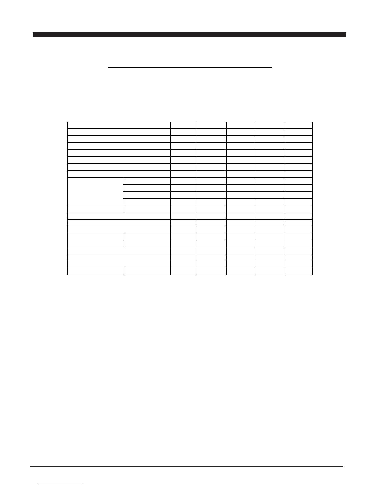
SPECIFICATIONS CONTENTS
AM/FM TUNER SECTION
DISASSEMBLY INSTRUCTIONS---------------------3
ADJUSTMENTLOCATIONS----------------------------4
ALIGNMENTPROCEDURES---------------------5 - 10
IC BLOCK DIAGRAMS----------------------------14 -20
VOLTAGE CHARTS--------------------------------11-13
BLOCK DIAGRAM---------------------------------------21
WIRING DIAGRAM-------------------------------------22
PRINTED CIRCUIT BOARDS---------------------30 -33
SCHEMATIC DIAGRAMS-------------------------23 - 29
EXPLODED VIEW/PARTSLIST(CABINET)---34- 36
IMPORTANT SERVICE SAFETYINFORMATION---2
ANTENNASYSTEM
FM:LEADWIRE OR75OHMJACK
TUNING RANGE
FM: 87.5 - 108MHz
AUDIO SECTION
SPEAKER IMPEDANCE : 4 OHM
GENERAL : 4.5W x 2
POWERINPUT :~AC 230V
AC POWER CONSUMPTION
MAIN DIM : 234(L)x156(W)x 237(H)mm
WEIGHT : 5.49Kg
NOTE: All the specifications and features are subject to change without notice.
7th Floor, Chung Mei Centre,
15A Hing Yip Street, Kwun Tong, Kowloon, Hong Kong.
Tel:(852)2790 3392 (12 Line), Fax: (852)2341 8874
Email Address: info@nelson.com.hk
MODEL:NE-599
SERVICE PUBLICATION
AM: 522 - 1620kHz
AM: FERRITE BAR
SPEAKER DIM : 196(L) x156(W) x237(H)mm
PORTABLE RADIO CASSETTE WITH CD/MP3 PLAYER
Page 3
2
IMPORTANT SERVICE SAFETY INFORMATION
ANTENNA
TERMINAL
OHMMETER
OM
EXPOSED
METAL
PART
TEST ALL
EXPOSED METAL
SURFACES
(READING SHOULD
NOTBEABOVE
0.5mA)
LEAKAGE
CURRENT
TESTER
EARTH
GROUND
DEVICE
UNDER
TEST
2-WIRE CORD
ALSO TESTWITH
PLUG REVERSED
(USING ACADAPTER
PLUG ASREQUIRED)
AC LEAKAGETEST
2. PRODUCT SAFETY NOTICE
some electrical and mechanical parts have special safety
related characteristics which are often not evident from
visual inspection. Nor can the protection they give
necessarily be obtained by replacing them with
components rated for higher voltage , wattage, etc. Parts
that have special safety characteristics are identified by
a on schematic and parts list. Use of a substitute
replacement that dose not have the same safety
characteristics as the recommended replacement part
might create shock, fire, and/or other hazards. Product
safety is under review continuously and new instructions are
issued whenever Appropriate.
3. Servicing precautions
CAUTION: before servicing the unit covered by this service
by this service manual and its supplements. Read and follow
the SAFETY PRECAUTIONS on this page.
NOTE: if unforeseen circumstances create a conflict
between the following servicing precautions and any of the
Safety precautions, always follow the safety precautions.
Remember: safety first.
General servicing precautions.
a. Always unplug the unit s AC power cord from the AC
power source Before:
(1)removing or reinstalling any component, circuit board,
module or any other unit assembly.
(2)disconnecting or reconnecting any unit electrical plug or
other Electrical connection.
(3)connecting a test substitute in parallel with an electrical
capacitor caution: a wrong part substitution or incorrect
polarity installation Of electrolytic capacitors may result in
an explosion hazard
b. Do not defeat any plug/socket b+ voltage interlocks with
which the unit covered by this service manual might be
equipped.
c. Do not apply AC power to this unit and/or any its electrical
assemblies unless all solid-state device heat sinks are
correctly installed.
d. Always connect a test unit instrument s ground lead to
the unit s chassis ground before connecting the test
instrument s positive lead always remove the test
instrument s ground lead last.
CAUTION: USE OF CONTROLS, ADJUSTMENTS OR
PERFORMANCE OF PROCEDURES HEREIN MAY
RESULT IN HAZARDOUS RADIATION
EXPOSURE.
DANGER: IF INTERLOCK FAILS OR IS DEFEATED, THE LASER
LIGHT IS ABLE TO FUNCTION. THE LASER IS
INVISIBLE, AVOID DIRECT EXPOSURE TO BEAM.
4. Laser precautions
Warning!
(1)When servicing.(Incase it isnecessary to confirmlaser
Beam emission ) besure not to place your eyesany
closer than 1or 30cm from thesurface of the objective
lens on the optical pickup block.
HANDLING THE LASERPICKUP
( 2)Laser Diodesare Extremely Susceptibleto damage from
static electricity even ifa static dischargedies not ruin
the diode, itcan shorten its lifeor cause itto work
improperly.When replacing the pickup, usea conductive
maton the floorand desk andwear a wrist band
connected to groundthrough a 1Mohm resistor
to protect the laserdiode from staticdamage. If thelens
should get dusty, blow off thedust carefully fromthe
object.
(3)There areno adjustable partsin the pickupassembly. If it
is defective, replace the wholepickup assembly.
1. SAFETY PRECAUTIONS
Before returning a unit to the customer, always make a safety
check of the entire unit, including, but not limited to the
following items:
a. Be sure that no built-in protective devices are defective
and/or have been defeated during servicing.
(1)protective shields are provided to protect both the
technician and the customer. Correctly replace all
missing protective shields including any removed for
servicing convenience.
(2)when reinstalling the chassis and/or other assemblies in
the cabinet, be sure to put back in place all protective
devices, including , but not limited to , nonmetallic
control knobs, insulating fishpapers. adjustment and
compartment covers/shields and isolating resistor/
capacitor networks. Do not operate this or permit it to be
operated Without all protective devices correctly
installed and functioning .
b. Be sure that there are no cabinet openings through which
an adult or child might be able to insert their fingers and
contact a hazardous voltage. Such openings include, but
are not limited to, excessively wide cabinet ventilation
slots, and an improperly fitted and/or incorrectly secured
cabinet back cover.
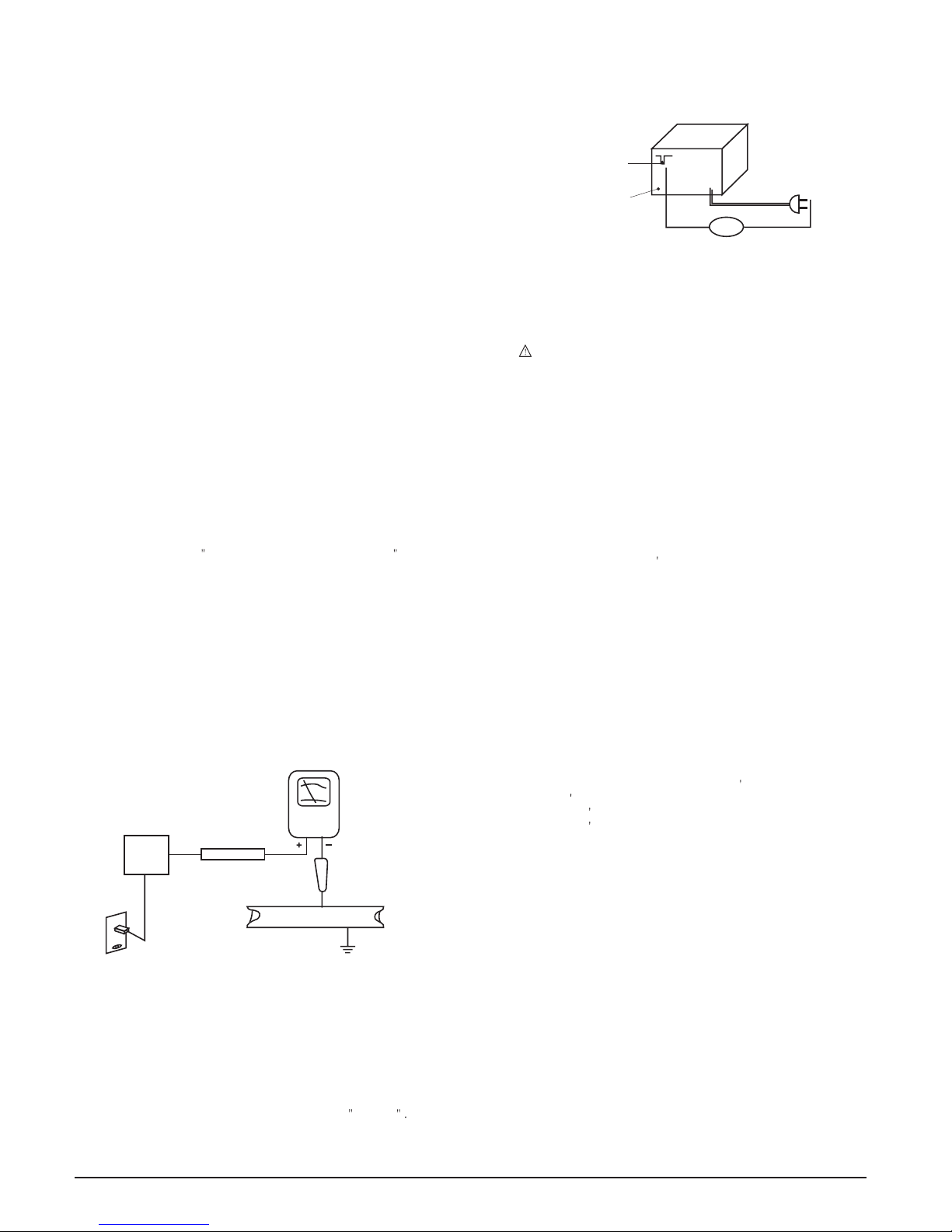
c. Leakage current hot check - with the unit completely
reassembled ,plug the AC line cord directly into a 120V
AC outlet. (Do not use an isolation transformer during this
test.) Use a leakage current tester or a metering system
that complies with American National standards Institute
(ANSI) C101.1 Leakage Current for Appliances and
Underwriters Laboratories(UL) 1410 (50.7). WITH THE
UNIT AC switch first in the ON position And then in the
OFF position, measure from a known earth ground (metal
water pipe, conduit, etc.) To all exposed metal parts of
the Unit (antennas, handle bracket, metal cabinet, screw
heads , metallic overlays, control shaft, etc.) Especially
any exposed metal parts that offer an electrical return
path to the chassis. Any current measured must not
exceed 0.5 milliamp, reverse the unit power cord plug in
the outlet and repeat test .
ANY MEASUREMENTS NOT WITHIN THE LIMITS
SPECIFIED HERENING INDICATE A POTENTIAL SHOCK
HAZARD THAT MUST BE ELIMINATED
RETURNING THE
UNIT TO THE CUSTOMER.
d. Insulation resistance test cold check:
unplug the power supply cord and connect a jumper wire
between the two prongs of the plug .
Turn on the power switch of the unit.
Measure the resistance with an ohmmeter between
jumpered AC PLUG AND EACH Exposed metallic cabinet
part on the unit, such as screw heads, antenna, control
shafts, handle brackets, etc. When the exposed metallic
part has a return path to the chassis , the reading should
be between 1 and 5.2 megohms. When there is no return
path to the chassis, the reading must be infinite If it is
not within the limits specified, there is the possibility of a
shock hazard, and the unit must be repaired and
rechecked before it is returned to the customer.
Page 4

DISASSEMBLY INSTRUCTIONS
3
Page 5
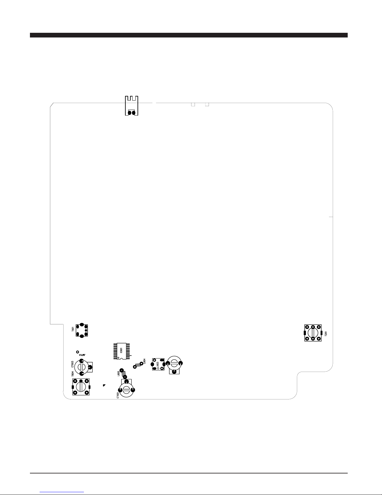
ADJUSTMENTLOCATIONS
4
Page 6
ALIGNMENT PROCEDURES
5
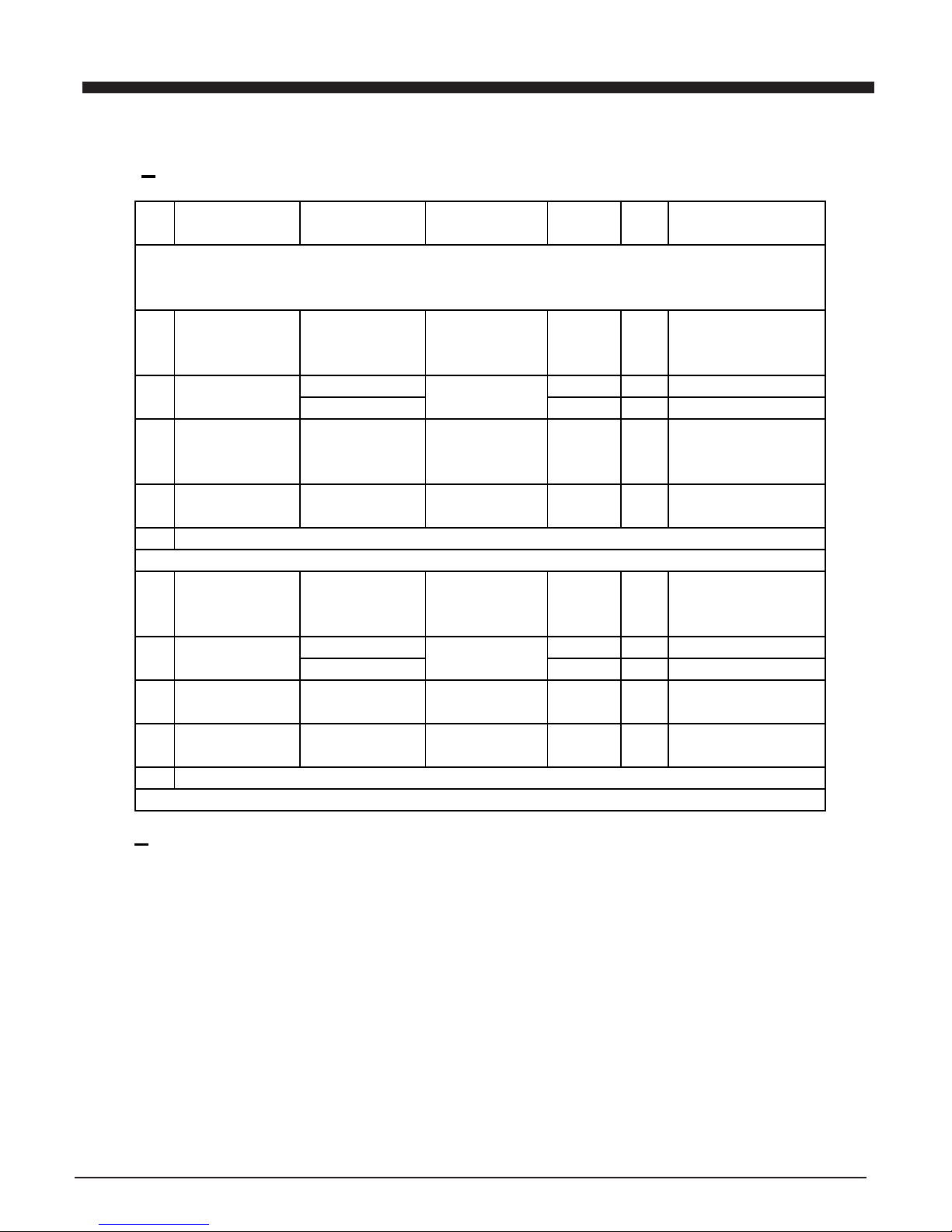
FM AND AM RF ALIGNMENT CHART ( IF )
Step item Input Circuit Output Circuit Tuner Adj - Adjustment
Setup Setup setting Point
Unless otherwise specified set switches as follows:
FM Function: FM
Adjust generator frequency to a center of the FM band where no FM broadcast exists
IF Connect FM IF Connect Co19 and GND FM in band Adjust for straight and
1 Adjustment sweep output IF-OUT terminal to end T602 symmetrical S-curve
terminal to IC102 IF sweep input terminal with max.amplitude.
2 FM Headphone jack or 87.5 MHz L604 Adjust L103 for max output
Band setup speaker terminal 108MHz C632 Adjust CT102 for max output
FM SG ANT. Headphone jack or 90.1 MHZ L605 Adjust for max.output and
3 Tracking (1) Terminal 90.1 MHz, speaker terminal MONO best waveform
1kHz, +-22.5kHz dev
4 Tracking (2) 106.1 MHz, 1 kHz Headphone jack or 106.1 MHz CT601 Same as above.
+-22.5 MHz dev speaker terminal
5 Repeat steps 3 and 4.
MW
IF Connect standard loop Connect input terminal MW in band Adjust tor max. amplitude
1 Adjustment antenna to output ter- genescope to detector end T601 with symmetrical 450 kHz.
minal of genescope output
2 MW Headphone jack or 522 kHz L603 Adjust L603 for max output
Band speaker terminal 1620 kHz CT602 Adjust CT602 for max output
3 Tracking (1) 612 kHz 400 kHz, Headphone jack or 612 kHz L604 Adjust for max.output and
3% mod speaker terminal best waveform
4 Tracking (2) 1404 kHz 400 kHz, Headphone jack or 1404 kHz CT603 Same as above.
3% mod speaker terminal
5 Repeat steps 3 and 4.
TAPE SECTION
HEAD ADJUSTMENT (AZIMUTH)
10 kHz test tape (example:MTT-114N) must be used for this adjustment. Connect to VTVM or oscilloscope to the headphone JCK or speaker terminal Press the play button.
Adjust the azimuth by using a screw driver to maintain the maximum L & R output voltage. Adjust tape. Please secure the
azimuth position by using locking paint.
RECODING BIAS OSCILLATOR FREQUENCY ADJUSTMENT
Connect the frequency counter to of R601 two ends.
Press REC button of tape B.
Adjust T201 obtain 60 kHz +-100 HZ
Page 7
ALIGNMENT PROCEDURES
10
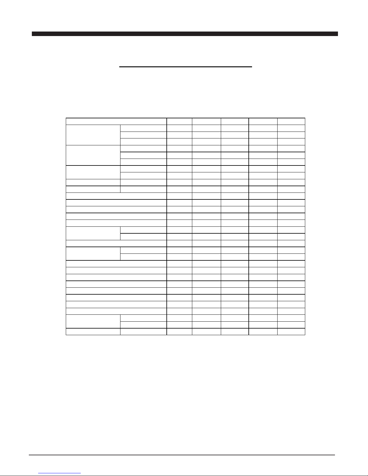
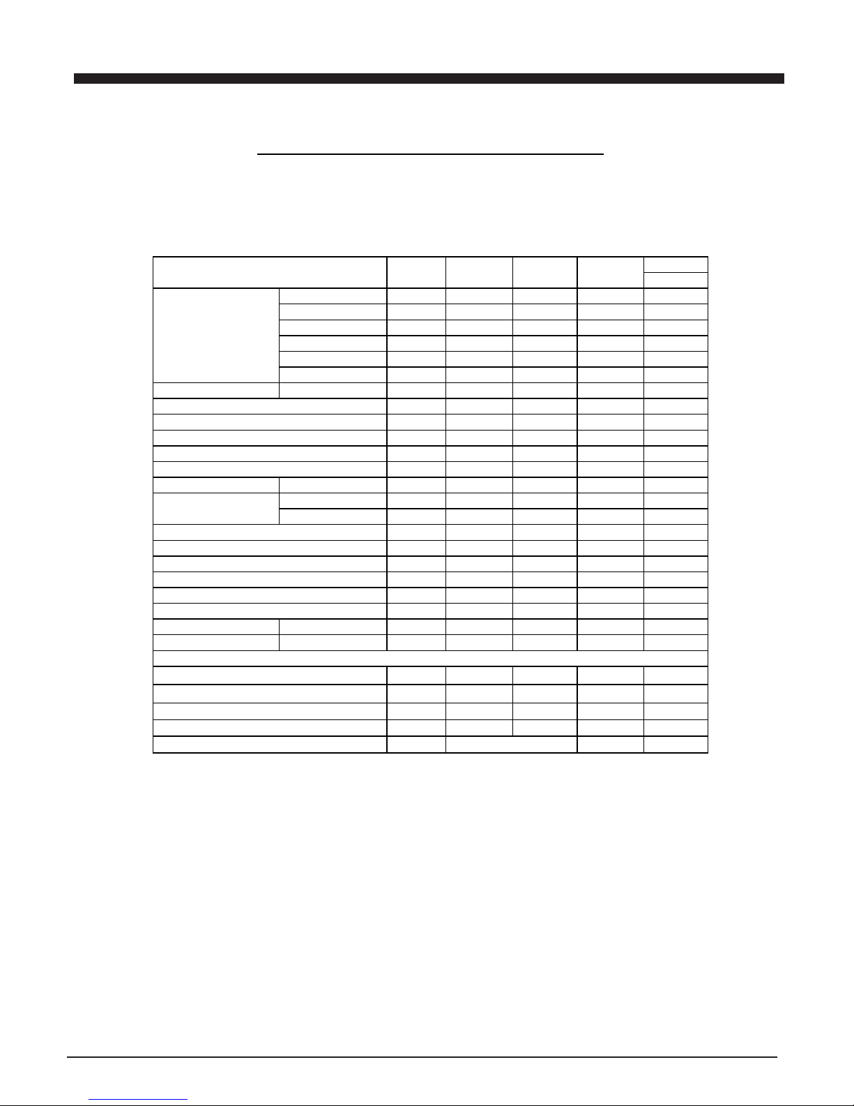
FM RECEIVER PERFORMANCE DATA
Band: FM
Supply Voltage:AC V
Standard Output: 50 mw
Dummy Load:4 Ohm
Modulation: 1 KHz 22.5 KHZ DEV
EQ or Tone at Flat Place Bass OFF Place
Measuring Items Unite Norm Limit Sample1 Sample2
30db Quieting 90.1 MHz db 18 26
Sensitivity 98.1 MHz db 18 26
106.1 MHz db 18 26
Auto Locked 90.1 MHz db 24 26
Sensitivity 98.1 MHz db 24 26
106.1 MHz db 24 26
ACA 2Sign +300 KHz db 18 12
-300 KHz db 18 12
Image Rejection AT 106.1 MHz db 20 16
IF Rejection AT 90.1 MHz db 50 40
-3db Limiting Sens . 1mv I/P db 18 22
AM Suppression 1mv I/P db 35 30
S/N (Mono ) 1mv I/P db 50 45
Stereo Sens db 18 24
Stereo Lamp On Sens. db 18 24
Separation R/L Mono R-L db 30 26
L-
R
db 30 26
50 us Audio Freq. Low Hz <40
Response-3db High KHz 10
Modulation Hum 1 mv I/P db 50 45
Hum & Noise(min.vol.) mv 0.8 1.5
Max. Out Harmonic Distortion % 20
Max. Output (MOD=40KHz) mW 5000 4500
Output (10% Dist) (MOD=40KHz) mW 4800 4500
Total Harmonic Distortion 1 mv I/P % 1 2
Over load signal (MOD 75KHz
)
db 110 100
OSC Drop Out 1 mv I/P V 190 207
Frequency Range Low MHz 87.5 +/-0.1
High MHz 108 +/-0.1
IF Frequency MHz 10.7 +/-0.2
Page 8
ALIGNMENT PROCEDURES
9
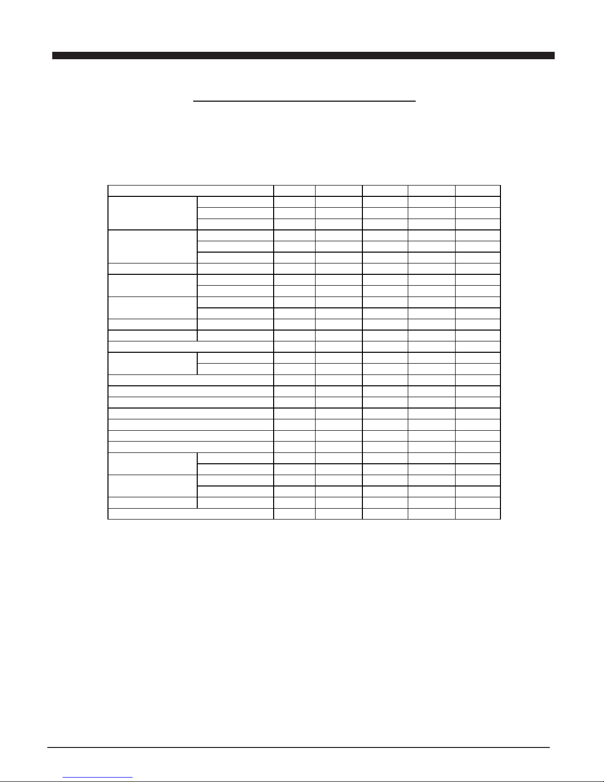
MW RECEIVER PERFORMANCE DATA
Band: MW
Supply Voltage:AC V
Standard Output: 50 mw
Dummy Load:4 Ohm
Modulation: 1 KHz 30%
EQ or Tone at Flat Place Bass OFF Place
Measuring Items Unite Norm Limit Sample1 Sample2
20db Quieting 612 KHz dB/M 66 70
Sensitivity 999 KHz dB/M 66 70
1404 KHz dB/M 66 70
Auto Locked 612 KHz dB/M 66 70
Sensitivity 999 KHz dB/M 66 70
1404 KHz dB/M 66 70
S/N 5mv/M 999 KHz dB 35 30
ACA +9 KHz dB 18 10
-9 KHz dB 18 10
Band Width-6dB +Side KHz 3 10
-Side KHz 3 10
Image Rejection AT 1404 KHz dB 35 30
IF Rejection AT 612 KHz dB 50 40
AGC FOM-10db 100mv/M dB 45 35
Audio Freq. Low Hz 60 <100
Response-6db High KHz 3 >2.2
Modulation Hum 100 mv/M dB 45 40
Hum (Volume At Min) mv 0.8 1.5
Max. Out Harmonic Distortion % 20
Max. Output (MOD=80%) mW 4500 4200
Output (10% Dist) (MOD=80%) mW 4500 4000
Total Harmonic Distortion 5mv/M % 2 4
OSC Drop Out 5mv/M V 190 207
Current No signal mA
Consumption Max mA
Frequency Range Low KHz 522 +/-10
High KHz 1620 +/-10
IF Frequency KHz 450 +/-2
Page 9
ALIGNMENT PROCEDURES
8
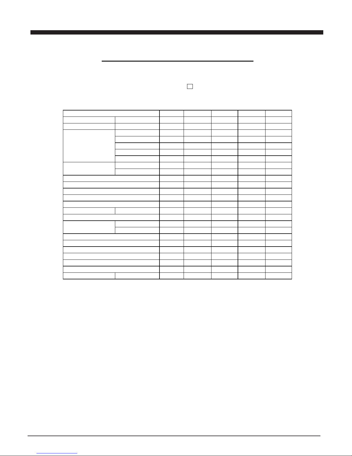
CASSETTE PLAYBACK PERFORMANCE DATA
Supply Voltage: AC V
Standard Output:50 mw
Dummy Load: 4 Ohm
0DB=1V
EQ or Tone at Flat Place Bass OFF Place
Tape Speed 4.76cm/sec.1
7
/
8
I
n
Measuring Items Unite Norm Limit Sample1 Sample2
Tape Speed Enor at 3 KHz % +3/-2
WOW & Flutter at 3 KHz % 0.25 0.35
Play Freq Response at Hz dB
at 100 Hz dB +/-2 +/-4
at 1 KHz dB 0 0
at 10 KHz dB +/-2 +/-4
at KHz dB
P/B S/N (1K odB)
AC Optetaion dB 50 45
Min Vol Hum & Noise AC Optetaion mv 0.8 1.5
Max Vol Hum & Nois
e
AC Optetaion mv 15 30
Max. Out Harmonic Distortion % 20
Max Output 0dB 1KHZ mw 4800 4500
10% THD Output (1KHz 0dB) mw 4500 4200
THD at Hz %
Track Crosstalk dB 45 40
Channel Separation R-L dB 40 30
L-R dB 40 30
Play Torque g/cm
F.F Torque g/cm
Rew Torque g/cm
Play Level 1K 0d
b
dB 0 0
Radio FM 1K 40kh
z
dB +/-2 +/-4
CD 1KHz-10db dB +/-2 +/-4
Page 10
ALIGNMENT PROCEDURES
9
CASSETTER REC/PLAY PERFORMANCE DATA
Supply Voltage: AC V
Standard Output:50 mw
Dummy Load: 4 Ohm
0DB=1V
EQ or Tone at Flat Place Bass OFF Place
Tape Speed 4.76cm/sec.1
7
/
8
I n
Measuring Items Unite Norm Limit Sample1 Sample2
Rec Blas System AC KH z 60 52
Erasing System Magnet 6PA
Erasing Ratio dB 38 32
R/P Frep Response at Hz dB
REC CD(-20dB) at 100 Hz dB +/-3 +/-6
100Hz ,1KHz, 10KHz at 1 KHz dB 0 ,+/-3
at 10 KHz dB +/-3 +/-6
R/P S/N FM 1mv/in dB 38 32
FM rec/playback ch separation 1KHz dB 35 30
R/P THD at -10dB 1KHz % 4 8
Line in Sens dB
R/P Channal Separatio
n
L-R dB 30 26
(1KHB 0dB) R-L dB 30 26
Record Level Tape= -10db dB 0 0
Radio FM 1KHz 12.5KHz dB +/-2 +/-3
CD 1KHz -20dB dB +/-2 +/-3
Page 11
ALIGNMENT PROCEDURES
10
CD/MP3 PLAYBACK PERFORMANCE DATA
Supply Voltage: AC V
Standard Output:50 mw
Dummy Load: 4 Ohm
0DB=1V
EQ or Tone at Flat Place Bass OFF Place
Measuring Items Unite Norm Limit Sample1 Sample2
WOW & Flutter %
Play Freq Response at 40 Hz dB - 3 - 4
(0dB) at 61 Hz dB - 2 - 3
at 127 Hz dB 0 - 3
at 1 KHz dB 0 0
at 10 KHz dB 0 - 3
at 20 KHz dB - 2 - 4
P/B S/N (YEDS) AC Optetaion dB 55 50
Min Vol Hum & Noise AC Optetaion mv 1 1.5
Max Vol Hum & Nois
e
AC Optetaion mv 3 5
Max Output mw 5000 4500
10% THD Output RMS mw 4500 4200
Max. Out Harmonic Distortion % 20 25
THD (-20dB) at 1 KHz % 0.5 1
Channel Separation R-L dB 55 50
YEDS (0dB 1KHz ) L-R dB 55 50
Channel Balance (1KHz -10dB) dB 1 2
Black Spot PHILIPS-444A UM 800 600
Finger Prints PHILIPS-444A TRAC
K
19 18
Interruption PHILIPS-444A UM 900 600
Deflection 731RA MM 1 0.9
Eccentricity 712R UM 210 140
Access Operation First Sec 3
Time Last Sec 13
MP3 PLAYBACK PERFORMANCE DATA
MP3 Playback Transfer Rate kbps 8-320
ID3 Support Version Ve
r
2.0
MP3 Max Readable Folder & Files Coun
t
512
MP3 Sampling rate KHz 48,44.1,34,24,22.05,16
Page 12
VOLTAGECHARTS
11
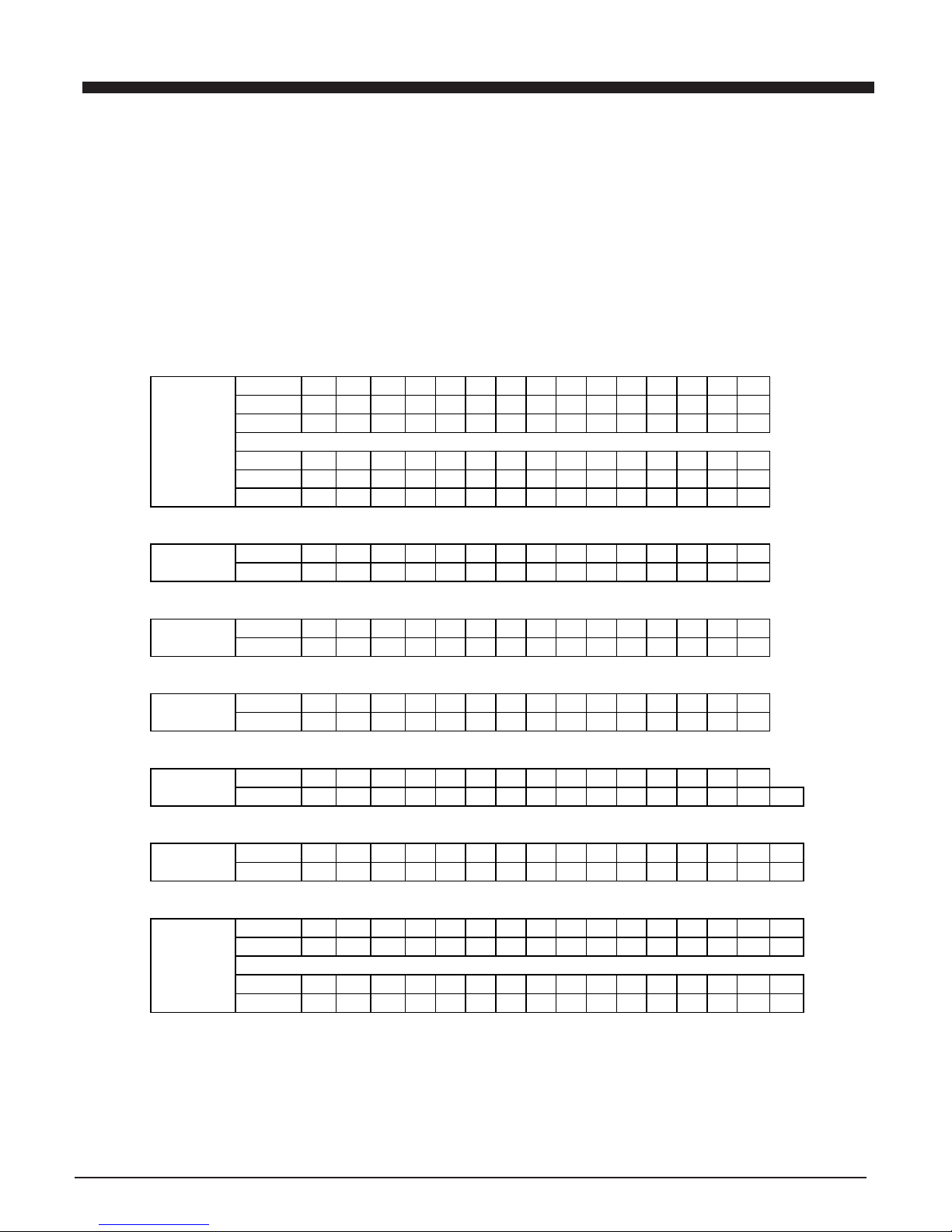
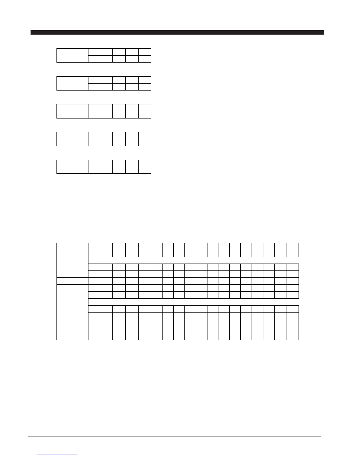
IC VOLTAGE TABLE
{DC12V,NO SIGNAL INPUT (EXCEPT FM STEREO BAND),VOLUME MINMUN}
AC 230V 50HZ TB2132 & TA8142AP & TC4052BP &PT2253A
PINS 1 2 3 456789101112131415
AM
0 0 3 0.2 3.1 3.1 2.4 2.5 0.5 0.8 2.5 2.2 1.2 1.2 0.6
FM.ST 0.8 0 2.8 0 3.1 3.1 2.5 2.2 1.2 0.8 2.4 2.1 1.2 1.2 0.6
IC601
TB2132 PINS 17 18 19 20 21 22 23 24 25 26 27 28 29 30
AM
0 3.1 1.1 3.1 3.1 3 1.9 3.1 3.1 3.1 3.1 0 3.1
FM.ST 0 3.1 1.1 3.1 3.1 0.1 1.4 3.1 2.8 3.1 3 0 3.1
IC201 PINS 1 2 3 456789101112131415
TA8142P TAPE
0 1.2 2.1 1.5 7 2.1 1.2 0 0 1.2 2.3 0 0.7 2.3 1.3
IC401 PINS 1 2 3 456789101112131415
PT2253A VOLUM
7.2 3.6 3.6 3.6 3.6 3.6 7.2 7.2 7.2 3.6 3.6 3.6 3.6 3.6
IC301 PINS 1 2 3 456789101112131415
TA8229K POWER
0 16.8 9 17 9 16 0 16 9 0.5 0 0 0.6 0 0
IC521 PINS 1 2 3 456789101112131415
TC4052BP FUNCT
0 0 0 000000-3.5 0-3.5 00000
PINS 1 2 3 456789101112131415
REMOTE 02.92.91.4000000002.82.82.8
IC951
TC9243F PINS 17 18 19 20
REMOTE 0 2.8 0 3
Page 13
VOLTAGECHARTS
12
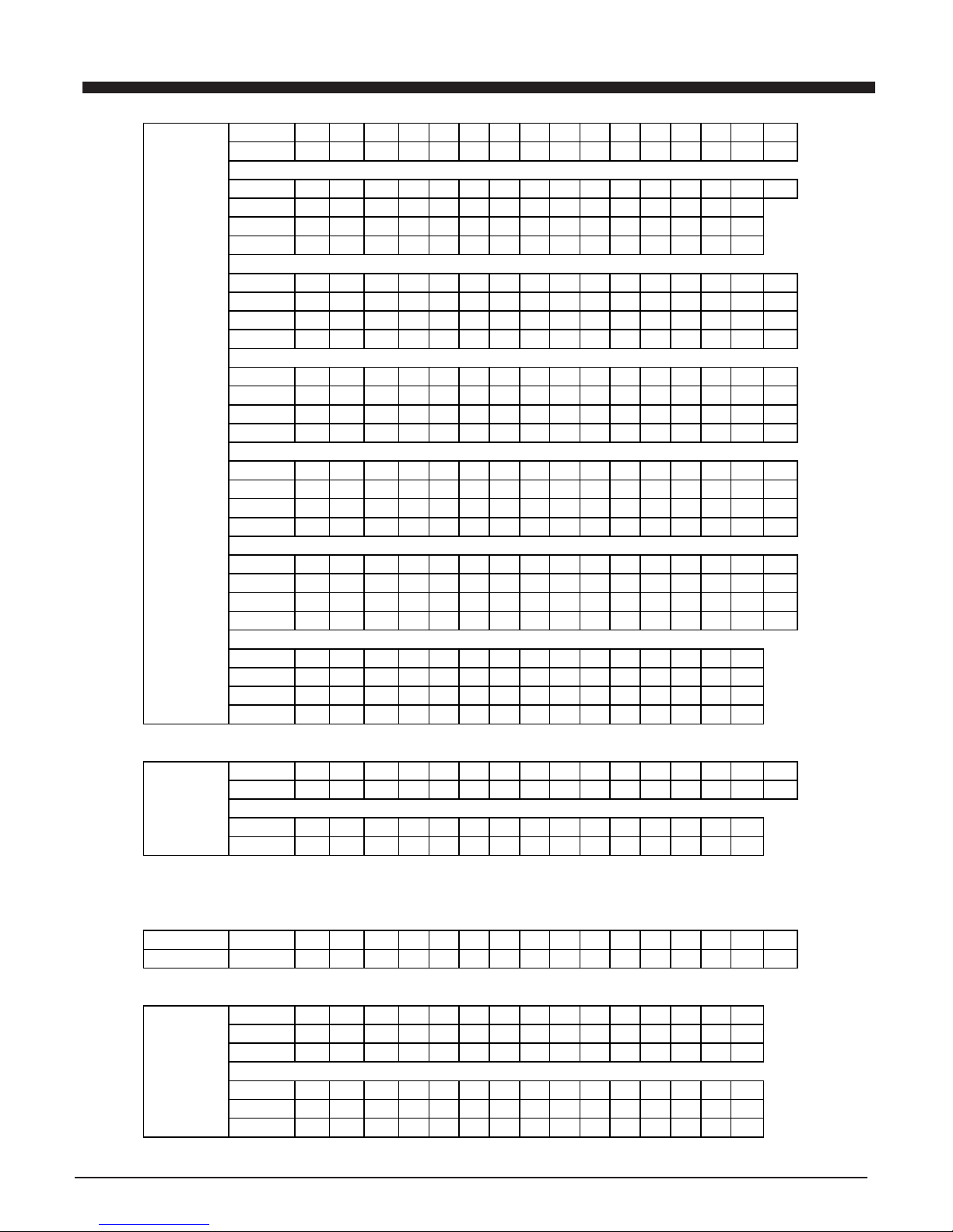
PINS 1 2 3 45678910111213141516
CPU
2.3 2.3 2.3 2.3 2.3 2.3 2.3 2.3 2.3 2.3 2.3 2.3 2.3 0 0 0
PINS 17 18 19 20 21 22 23 24 25 26 27 28 29 30 31 32
RADIO
0 4.7 4.7 0 4.5 2.7 0 4.6 0 4.7 4.7 1.2 0 0 0.2 0.2
TAPE
0 4.7 4.7 0 4.5 2.7 4.4 4.6 0 4.7 4.7 1.2 0 0 4.7 4.7
U1 CD
0 4.7 4.7 0 4.5 3.9 4.4 0 0 4.7 4.7 1.2 0 0 4.7 4.7
TC94A09 PINS 33 34 35 36 37 38 39 40 41 42 43 44 45 46 47 48
F-209 RADIO
2.54.60 04.7000000000 0 0
TAPE
0.60.62.204.700000000502.1
CD
4.71.20.204.700004.62.500504.3
PINS 49 50 51 52 53 54 55 56 57 58 59 60 61 62 63 64
RADIO
0 0 0 00000000000 0 0
TAPE
2.1 0 1.7 4.3 2.1 0 0 1.9 2.1 5 1.2 1.1 1.1 2.1 1.1 2.1
CD
2.1 2.1 2.1 2.1 2.1 1.6 0 2.1 2.1 5 2.6 2.7 2.7 2 2.4 2.1
PINS 65 66 67 68 69 70 71 72 73 74 75 76 77 78 79 80
RADIO
0 0 0 00000000001.14.74.7
TAPE
2.12.22.22.22.22.22.22.24.305000.64.74.7
CD
2.1 2.2 2.2 2.1 2.4 2.3 2.1 2.2 4.3 2.5 5 0 0 1.9 2.2 4.7
PINS 81 82 83 84 85 86 87 88 89 90 91 92 93 94 95 96
RADIO
0 0 0 000001.34.73.64.72.31.504.7
TAPE
0 0 0 000000.74.73.64.72.31.704.7
CD
0 0 0 0000004.73.64.72.31.804.7
PINS 97 98 99 100
RADIO
2.3 2.3 2.3 2.3
TAPE 2.3 2.3 2.3 2.3
CD 2.3 2.3 2.3 2.3
PINS 1 2 3 45678910111213141516
MOTOR 3.6 3.6 2.1 2.1 0 1.7 7.95 0 2.1 2.1 3.6 3.6 0 7.3 0.9 0
U4
MM1469 PINS 17 18 19 20 21 22 23 24 25 26 27 28
MOTOR 3.6 3.6 2.1 2.1 7.9 7.9 2.1 3.6 2.1 3.6 3.6 0
U3 PINS 1 2 3 45678910111213141516
TA2153FN CD
4.22 2 222203.6024220.90
PINS 1 2 3 456789101112131415
FM
AM
PINS 17 18 19 20
FM
AM
Page 14
VOLTAGECHARTS
13
IC302 PINS 1 2 3
KA7808
14 0 8
IC303 PINS 1 2 3
7806
12.9 0 6
Q307 PINS E B C
8050
7.6 8.2 11.9
IC901 PINS 1 2 3
RECEIVEER 4.6 0 4.6
IC304
PINS 123
7805 7.9 0 5
REMARK : ALL THE DATA IN THE TABLE IS FOR.REFERENCE ONLY
FOR FM.ST BAND , FM STEREO INDICATOR MUST BE ON.
PINS 1 2 3 456789101112131415
U2 MP3
3.7 3.3 0 0-2.8 4.6 4.7 0-2.8 3.3 1.7 0-3.2 0-3.3 0 1.6 1.6 0-2.3
TC94A02F PINS 16 17 18 19 20 21 22 23 24 25 26 27 28 29 30
-7 MP3
3.3 3.3 2.5 0 0 0 1.3 0 2.5 2.5 1.3 1.3 0 0 3.3
PINS 31 32 33 34 35 36 37 38 39 40 41 42 43 44 45
U3 MP3
0-3.4 0-3.3 0-2.6 0-2.8 3.3 0-3.4 0-2.3 0-2.3 0 0 0-3.4 0-3.3 0-3.4 3.3 3.3
PINS 46 47 48 49 50 51 52 53 54 55 56 57 58 59 60
MP3
0 0 0 0-3 0-3 0-3 2.5 0-3 0 0-3 0 1.3 1.3 2.5 1.5
PINS 61 62 63 64
MP3
2.5 1 1.2 0
Page 15
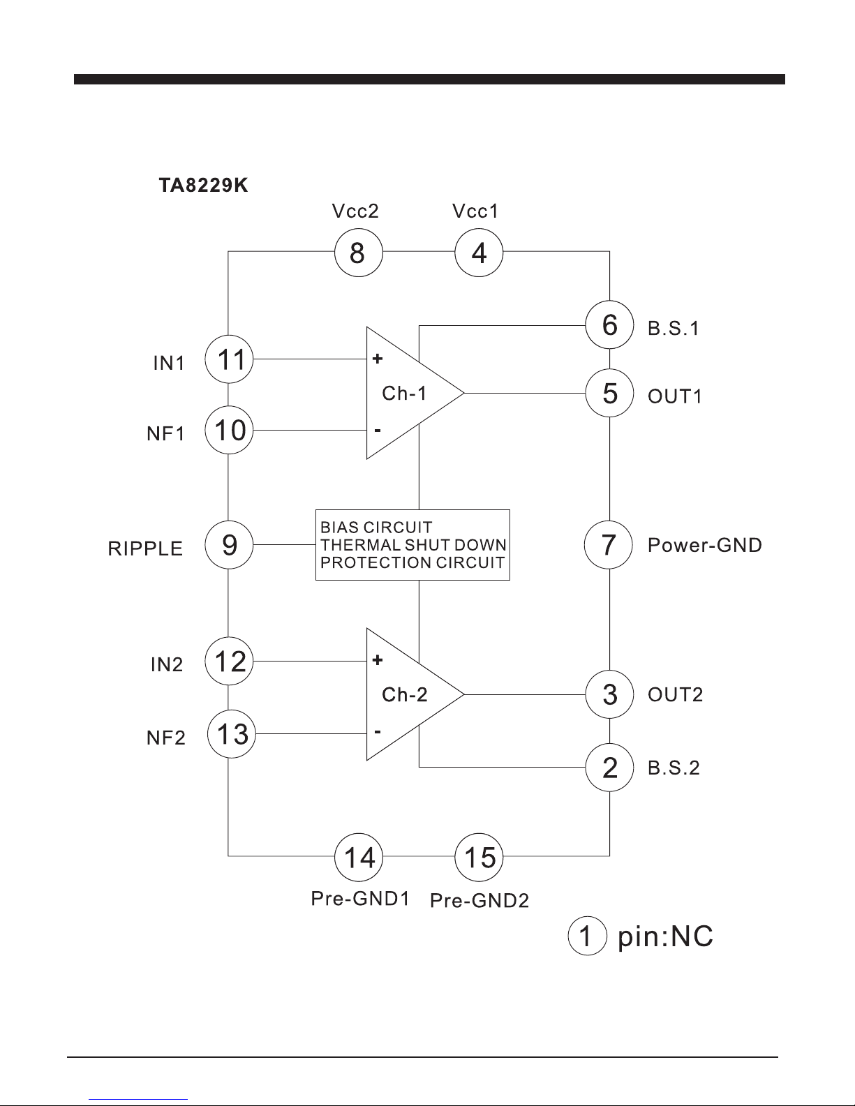
14
IC BLOCK DIAGRAM
Page 16
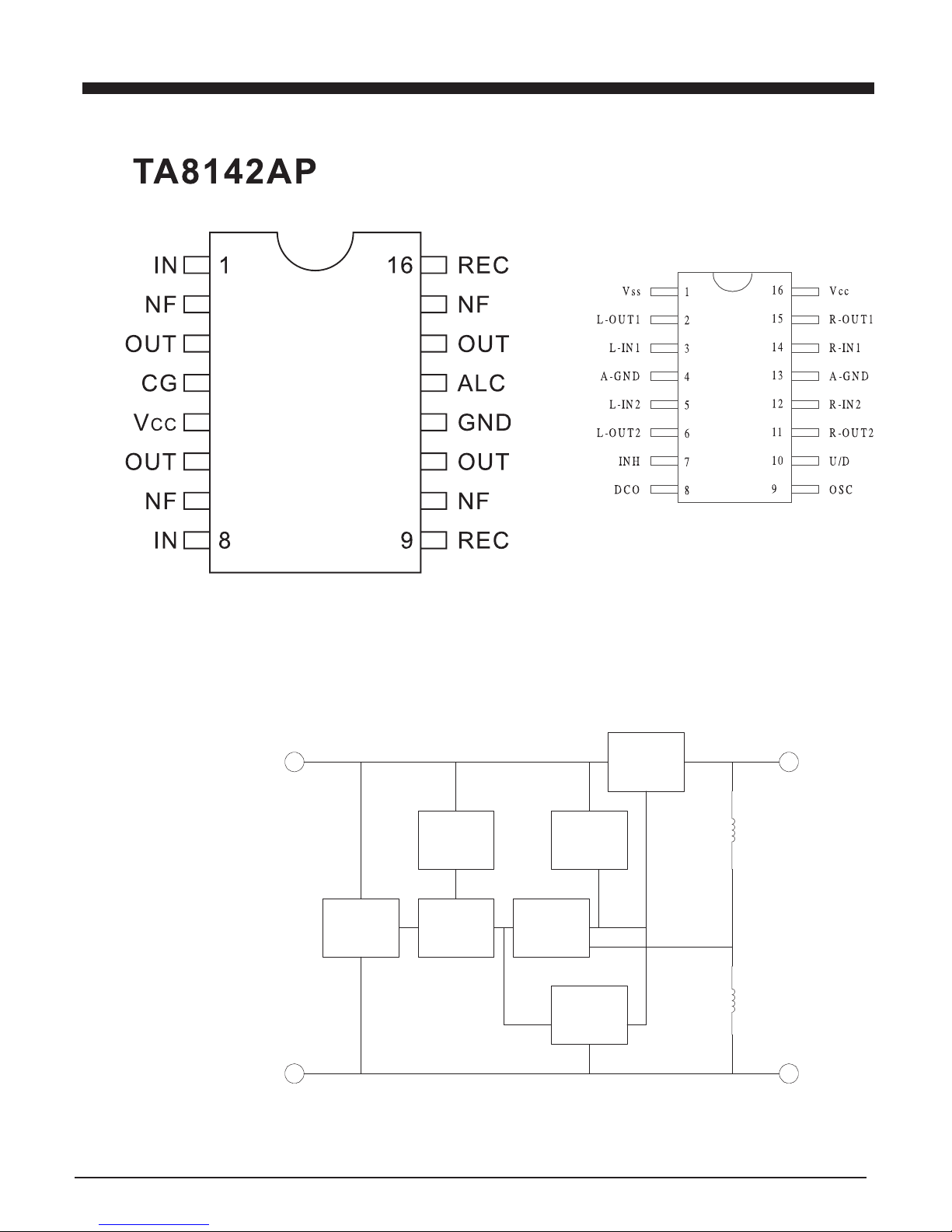
15
IC BLOCK DIAGRAM
PT2253A
SERIES
PASS
ELEMENT
CURRENT
GENERATOR
SOA
PROTECTION
STARTING
CIRCUIT
ERROR
AMPLIFIER
THERMAL
PROTECTION
INPUT
1
OUTPUT
3
GND
2
R20
R19
REFERENCE
VOLTAGE
KA7808
KA7805
Page 17

16
IC BLOCK DIAGRAM
Page 18

17
IC BLOCK DIAGRAM
Page 19

18
IC BLOCK DIAGRAM
Page 20

19
IC BLOCK DIAGRAM
TMAX
PDO
P2Vref
VSS
SBOK
SBSY
DOUT
COFS/OT22: Decoder Reset
SPCK/OT20 : EV-UP
SPDA/OT21:Mute Output
/HSO/OT19:EV-DOWN
TESTC :
IN1 :Funct In/Out Select
P2-3 :EQB
P2-2 :PLL-CE
P2-1 :PLL-CLK
P2-0 :PLL-DATA
P4-3/SCK/SCL :I2C Clk
P4-2/Sin1/SDA :I2C Data
VDD
P4-1/Sin2 :I2C Request
P4-0/ADin4/BUZR : PU Select
P3-2/ADin2 :KeyAD2
P3-3/ADin3 : Tuner Select
P3-1/ADin1 :KeyAD1
P3-0/DCref : EQA
P1-3 : Funct B
P1-2 : Funct A
P1-1 :CDRW/ST
P1-0 :Power Out
MVSS
MVDD
S16/P8-1 :AOUT
S17/P8-2 :DoorInSW
S14/OT18 :LRCKout
S12/OT16
S10/OT14
S8/OT12
S6/OT10
S3/OT7
S18/P8-3 :InnerSW
S15/P8-0 :BCKout
S11/OT15
S13/OT17
S9/OT13
S7/OT11
S5/OT9
S4/OT8 LCD output
S2/OT6
S1/OT5
DVS
R
RO
DVR
R
DVDD
LO
DVRL
DVSL
CD_SYNC
NC/VPP
Power Detect: /HOLD
/RST
Remote: INT
R
75KHz XTAL: MXO
75KHz XTAL: MXI
MVSS
MVDD
COM1/OT1
COM2/OT2
COM3/OT3
COM4/OT4
LPFN
LPFO
VCOF
AVSS
SLCO
RFI
AVDD
RFCT
RFZI
RFRP
FEI
TEZI
TRO
FOO
RFGC
Vref
FMO
TEBC
2Vref
DMO
VDD
SEL
XI
XO
XVDD
\VSS
XVSS
TEI
SBAD
PVref
Reset input
Hold input
Interrupt input
MCU Power supply
MCU Oscillator
CD input/output port
DAC inpu
t
I/O port
MCU
Power supply
TC94A09F
(QFP100pin)
Top View
85 90 95
45 40 35 31 50
75
70
65
60
55
51
80
81
20
25
30
1
15
10
5
100
LCD/LED driver,I/O,CD output port
(LCD:4*18=Max.72 segment)
(LED:Max.18 segment)
Page 21

20
IC BLOCK DIAGRAM
TB2132FN
Page 22

BLOCK DIAGRAM
21
Page 23

WIRING DIAGRAM
22
Page 24

SCHEMATIC DIAGRAMS
23
Page 25

SCHEMATIC DIAGRAMS
24
Page 26

SCHEMATIC DIAGRAMS
25
Page 27

SCHEMATIC DIAGRAMS
26
Page 28

SCHEMATIC DIAGRAMS
27
Page 29

SCHEMATIC DIAGRAMS
28
Page 30

SCHEMATIC DIAGRAMS
29
Page 31

PRINTED CIRCUIT BOARDS
30
Page 32

PRINTED CIRCUIT BOARDS
31
Page 33

PRINTED CIRCUIT BOARDS
32
Page 34

PRINTED CIRCUIT BOARDS
33
Page 35

34
EXPLODED VIEW/PARTS LIST (CABINET)
Page 36

35
EXPLODED VIEW/PARTS LIST (CABINET)
ITEM PART NO. DESCRIPTION QTY ITEM PART NO. DESCRIPTION QTY
1 356-059300-8890 CASS KNOB COVER LENS 1 56 461-05990B-1000 PCB BRACKET-B 2
2 367-059900-8890 CASSETTE DOOR LENS 1 57 188-000400-00 LEAF SWITCH 1
3 333-059900-8890 FRONT LENS 1 58 374-059300-5Y20 CD DOOR BRACKET 1
4 357-059300-6500 CASSETTE KNOB COVER 1 59 358-.059300-6500 CD DOOR 1
5 358-059300-6500 CASSETTE DOOR 1 60 466-059300-1C20 CD DOOR DOCK 1
6 177-023502-01 STEREO JACK 1 61 408-059307-2500 DOOR OPEN BUTTON 1
7 425-059300-1C20 CASS KNOB-RECORD 1 62 461-059303-2500 DOOR OPEN BU BRACKE 1
8 425-059301-1C20 CASS KNOB-PLAY 1
9 425-059302-1C20 CASS KNOB-F.REW 1
10 425-059303-1C20 CASS KNOB-F.FWD 1
11 425-059304-1C20 CASS KNOB-PAUSE 1 P1 173-059304-01 HEADPHONE BOARD 1
12 425-059314-1C20 CASS KNOB-STOP 1 P2 173-059903-01 FUNCTION KEY BOARD 1
13 303-000081-0001 CASS KNOB FIXER 1 P3 173-059905-01 BAR BACK LIGHT BOARD 2
14 311-059900-6500 FRONT CABINET 1 P4 173-059306-01 LED BACK LIGHT BOARD 1
15 412-059900-2490 FUNCTION BUTTON 7 P5 173-059302-01 CPU+CD/RW(2153) 1
16 472-059901-1000 FUNCTION BUTTON BASE 1 P6 173-059301-01 A/F+R/P+5W AF 1
17 188-011511-01 TACT SWITCH 13
18 412-059903-2490 TUNER BUTTON 1
19 412-059904-2490 CD BUTTON 1
20 412-059905-2490 TAPE BUTTON 1 S1 203-300200-08 SCREW 3X8 P/A + 4
21 472-059908-1000 CD/TUNER BUTTON BASE 1 S2 203-300200-10 SCREW 3X10PA 20
22 337-059901-3890 LIGHT LENS-LEFT 1 S3 203-350800-18 SCREW 3.5X18PWA 2
23 470-059901-1C20 LIGHT COVER-LEFT 1 S4 203-300700-10 SCREW 3X10KA 6
24 149-050605-01 LED 2 S5 203-301720-08 SCREW M3X8A 6
25 133-6038LM-5A IR RECEIVER MODULE 1 S6 203-300200-12 SCREW 3X12PA 2
26 134-059554-07 LCD DISPLAY 1 S7 203-200200-06 SCREW 2X6PA 2
27 461-050122-1100 LCD REFLECTOR 1 S8 207-261600-01 SCREW 2.6X10PWB-10W 4
28 148-030000-40 LED 1 S9 203-260200-06 SCREW 2.6X6PA 1
29 461-059520-1010 CASS DOOR BRACKET 1
30 218-057512-12 DECK MACH 1
31 337-059901-3890 LIGHT LENS-RIGHT 1
32 470-059902-1C20 LIGHT COVER-RIGHT 1
33 420-05990P-2490 POWER BUTTON RING 1
34 403-059904-2490 POWER/STANDBY BUTTON 1
35 472-059905-1000 POWER BUTTON BASE 1
36 403-059902-2490 VOLUME BUTTON 1
37 408-059904-2490 SKIP BUTTON 2
38 408-059903-2490 STOP BUTTON 1
39 408-059902-2490 PLAY BUTTON 1
40 420-059902-2490 VOLUME BUTTON RING 1
41 472-059905-1000 VOLUME BUTTON BASE 1
42 156-582313-02 X’FORMER 1
43 303-000090-0101 MOUNTING POST 4
44 380-057510-5Y20 BATTERY DOOR 1
45 381-057510-5Y20 BATTERY BOX 1
46 322-059301-5Y20 REAR CABINET 1
47 303-000010-0000 AC POWER SWITCH COVER 1
48 188-011531-02 AC POWER SWITCH 1
49 185-01213-11 BEAT CUT SWITCH 1
50 185-062311-01 RESET SWITCH 1
51 179-026100-00 COAXIAL FM ANT. JACK 1
52 213-000005-16 CUSHION RUBBER 4
53 219-213CJM-02 CD MECHANISM 1
54 303-000041-0001 DUST COVER 1
55 461-05990A-1000 PCB BRACKET-A 2
Page 37

36
EXPLODED VIEW/PARTS LIST (CABINET)
Page 38

Component list with price
PART NO. DESCRIPTION UNIT QTY. PER
-------------------------------
-
---------------------------------------------------------------------------------------
-
001-059394-06 NE-593 BLUE LED BACK LIGHT BD SE 1
149-050624-30 High Intensity LED Blue 120Deg PC 2
HKL-504SBCK-2 FLAT HEAD "LED"
194-232015-02 28# FLAT CABLE 150MM PC 1
W/HOUSING JS-1124-2 2.0 PITCH
114-221012-05 RESISTOR (1/16W) 220 OHM ?% PC 2
HIGH GRADE
173-059306-01 NE-593 LED BACK LIGHT BOARD PC 1
59x15x1.6MM UL 94HB
001-059973-07 NE-599MP3 5W HEADPHONE W/EMC SE 1
177-023502-01 STEREO JACK EJ-3506-202 W/SW PC 1
194-232058-05 28# FLAT CABLE 580MM PC 1
W/HOUSING JS-1124-5 2.0 PITCH
114-181012-05 RESISTOR (1/16W) 180 OHM ?% PC 2
HIGH GRADE
121-103500-82 C.CAP 0.01 UF (50V) +80,-20% PC 2
161-025200-03 FERRITE BEAD ?3.5x?1.3x3mm P C 3
2?T X 0.3MM
173-059904-01 NE-599 5W HEADPHONE BOARD PC 1
19x32x1.6MM UL 94HB
001-059995-11 NE-599MP3 FUNCTION KEY BOARD SE 1
133-6038LM-5A IR RECEIVER MODULE FM-6038LM- PC 1
5A "OPTO-SENSOR" 180?
134-059950-0A MP3 LCD 91-42912-B01(V.A)209IC PC 1
69x25MM 14 PIN L=20MM (599)
148-030000-40 LED ?3MM RED (SHORT) SGP PC 1
188-011511-01 TACT SWITCH 1102-2 H 4.3MM PC 16
160 ?30gf
194-232018-05 28# FLAT CABLE 180MM PC 1
W/HOUSING JS-1124-5 2.0 PITCH
194-232020-06 28# FLAT CABLE 200MM PC 1
W/HOUSING JS-1124-6 2.0 PITCH
194-232020-07 28# FLAT CABLE 200MM PC 1
W/HOUSING PH2.0-7P 2.0 PITCH
194-232022-05 28# FLAT CABLE 220MM PC 1
W/HOUSING PH2.0-5P 2.0 PITCH
203-300200-10 TAPPING SCREW 3 X 10PA PC 2
206-060304-11 FIBRE WASHER 6 X 3 X 0.4MM PC 2
234-050100-01 DRAFTING FILM 69 x 25 x 0.15MM PC 2
"NELSON"
260-080808-00 PAD CORK 8x8x8MM W/ 2 side A PC 1
461-050122-1100 LCD REFLECTOR REV2. INJ ABS PC 1
WHITE
114-101012-05 RESISTOR (1/16W) 100 OHM ?% PC 2
HIGH GRADE
114-102012-05 RESISTOR (1/16W) 1K OHM ?% PC 1
HIGH GRADE
114-103012-05 RESISTOR (1/16W) 10K OHM ?% PC 4
HIGH GRADE
114-152012-05 RESISTOR (1/16W) 1.5K OHM ?% PC 2
Page 39

Component list with price
PART NO. DESCRIPTION UNIT QTY. PER
-------------------------------
-
---------------------------------------------------------------------------------------
-
HIGH GRADE
114-153012-05 RESISTOR (1/16W) 15K OHM ?% PC 1
HIGH GRADE
114-202012-05 RESISTOR (1/16W) 2K OHM ?% PC 2
HIGH GRADE
114-221012-05 RESISTOR (1/16W) 220 OHM ?% PC 3
HIGH GRADE
114-224012-05 RESISTOR (1/16W) 220K OHM ?% PC 1
HIGH GRADE
114-272012-05 RESISTOR (1/16W) 2.7K OHM ?% PC 2
HIGH GRADE
114-332012-05 RESISTOR (1/16W) 3.3K OHM ?% PC 3
HIGH GRADE
114-392012-05 RESISTOR (1/16W) 3.9K OHM ?% PC 2
HIGH GRADE
114-472012-05 RESISTOR (1/16W) 4.7K OHM ?% PC 1
HIGH GRADE
114-473012-05 RESISTOR (1/16W) 47K OHM ?% PC 3
HIGH GRADE
114-682012-05 RESISTOR (1/16W) 6.8K OHM ?% PC 2
HIGH GRADE
120-107302-20 E. CAP (16V) 100UF +/- 20% PC 2
HIGH GRADE ?5 x 11MM
120-335502-20 E. CAP 50V 3.3UF +/- 20% PC 1
HIGH GRADE ?5 x 11MM
120-475502-20 E. CAP 50V 4.7UF +/- 20% PC 1
HIGH GRADE ?5 x 11MM
121-102500-82 C.CAP 0.001 UF (50V) +80,-20% PC 1
121-104300-82 C.CAP 0.1 UF (16V) +80 -20% PC 3
130-514148-05 DIODE IN4148 BRAND: "COS" PC 2
DAIWA
131-09014C-38 TRANSISTOR S9014C HI LITE PC 3
CENTRE B
173-059933-01 NE-599MP3 FUNCTION KEY BOARD PC 1
131.6x94.7x1.6MM UL 94HB
195-200011-04 WAFER JS-1125-4S / JM 24181-4 PC 1
PH-4A 180?4 POLES 2.0MM PITCH
020-059940-01 NE-599 BAR BACK LIGHT BOARD SE 1
149-030600-31 High Intensity LED Blue 20 Deg PC 2
ROUND HEAD, GKL-C30D4CBCB-C6C
173-059905-01 NE-599 BAR BACK LIGHT BOARD PC 2
13x8x1.6MM UL 94HB
194-232015-04 28# FLAT CABLE 150MM PC 1
W/HOUSING JS-1124-4 2.0 PITCH
001-059935-01 NE-599MP3 A/F+R/P 5W AUDIO AC SE 1
BIAS BOARD (TA2132FN) W/EMC
122-100030-01 TRIMMER 10 PF (3 LEGS) ROUND PC 1
Vertical Mounting
122-200030-01 TRIMMER 20 PF VERTICAL MOUNT PC 2
(3 PINS) ?8MM
Page 40

Component list with price
PART NO. DESCRIPTION UNIT QTY. PER
-------------------------------
-
---------------------------------------------------------------------------------------
-
130-220262-S0 FM TUNING DIODE 1SV262 SMD PC 2
TOSHIBA
130-231V02-03 AM DOUBLE TUNING DIODE HN1V02H PC 1
CLASSIFICATION "B" TOSHIBA
150-007805-61 VOLTAGE REGULATOR IC 5V KA7805 PC 1
150-007806-61 VOLTAGE REGULATOR IC 6V KA7806 PC 1
150-007808-26 VOLTAGE REGULATOR 8V MC7808CT PC 1
ON SEMICONDUCTOR
150-08229K-14 IC TOSHIBA TA8229K PC 1
150-2132FN-14 IC TOSHIBA TB2132FN PC 1
174-162252-03 5 T 1.6L 250V ? X 20MM FUSE PC 1
VDE SEMKO APP
174-202252-03 5 T 2L 250V ?5 X 20MM FUSE PC 1
VDE SEMKO APP
177-070000-01 SPEAKER TERMINAL BOARD (505) PC 1
1x4 PIN "MSC" (MSP-104-01)
185-062311-01 REC. SWITCH PS-62D01 <300gf W/ PC 1
SHORTING, PS-62D03 (SHUN KAI)
188-011531-02 TACT SWITCH 1102VA-2 H 1.4MM PC 1
160 +/-30gf
194-214015-A3 24# UL1007 WIRE 150MM (B/B/R) PC 1
W/HOUSING PH2.0-3P PH2.0
194-232015-02 28# FLAT CABLE 150MM PC 2
W/HOUSING JS-1124-2 2.0 PITCH
194-232035-09 28# FLAT CABLE 350MM PC 1
W/HOUSING JS-1124-09 2.0 PITCH
202-032300-02 FUSE HOLDER (0.4mm) "NEW" PC 4
SAME 202-032300-00
202-057506-01 HEAT-SINK "U" TYPE 0.8mm <575> PC 1
for IC 7808, TR 2SB772
202-059902-01 HEAT SINK 5W FOR TA8229K (599) PC 1
204-300000-08 MACHINE SCREW M3 X 8 PM PC 4
205-300001-01 NUT M3 PC 1
261-101010-09 SPONGE 10 X 10 X 10 PC 2
107-101070-28 CERAMIC FILTER FM LT10.7MA5 PC 2
(RED) "SPECIAL"
107-104500-38 CERAMIC FILTER AM SFU450B PC 1
"SPECIAL"
107-201070-28 DISCRIMINATOR FM JT10.7MG3 PC 1
(RED) "SPECIAL"
108-000750-01 CRYSTAL 75KHz ETK-75.000WBN PC 1
3 X 8MM 20 ppm 12.5pf
114-100012-05 RESISTOR (1/16W) 10 OHM ?% PC 3
HIGH GRADE
114-100301-05 RESISTOR 10 OHM 1/2W ?% PC 1
114-101012-05 RESISTOR (1/16W) 100 OHM ?% PC 3
HIGH GRADE
114-102012-05 RESISTOR (1/16W) 1K OHM ?% PC 7
HIGH GRADE
114-103012-05 RESISTOR (1/16W) 10K OHM ?% PC 8
Page 41

Component list with price
PART NO. DESCRIPTION UNIT QTY. PER
-------------------------------
-
---------------------------------------------------------------------------------------
-
HIGH GRADE
114-104012-05 RESISTOR (1/16W) 100K OHM ?% PC 11
HIGH GRADE
114-105012-05 RESISTOR (1/16W) 1M OHM ?% PC 1
HIGH GRADE
114-122012-05 RESISTOR (1/16W) 1.2K OHM ?% PC 1
HIGH GRADE
114-123012-05 RESISTOR (1/16W) 12K OHM ?% PC 1
HIGH GRADE
114-152012-05 RESISTOR (1/16W) 1.5K OHM ?% PC 1
HIGH GRADE
114-183012-05 RESISTOR (1/16W) 18K OHM ?% PC 2
HIGH GRADE
114-202012-05 RESISTOR (1/16W) 2K OHM ?% PC 1
HIGH GRADE
114-220012-05 RESISTOR (1/16W) 22 OHM ?% PC 3
HIGH GRADE
114-220201-05 RESISTOR 22 OHM 1/4W, ?% PC 1
114-221012-05 RESISTOR (1/16W) 220 OHM ?% PC 2
HIGH GRADE
114-222012-05 RESISTOR (1/16W) 2.2K OHM ?% PC 5
HIGH GRADE
114-223012-05 RESISTOR (1/16W) 22K OHM ?% PC 9
HIGH GRADE
114-22A012-05 RESISTOR 2.2 OHM 1/16W ?% PC 2
114-271012-05 RESISTOR (1/16W) 270 OHM ?% PC 2
HIGH GRADE
114-331012-05 RESISTOR (1/16W) 330 OHM ?% PC 5
HIGH GRADE
114-331201-05 RESISTOR 330 0HM 1/4W, ?% PC 1
114-332012-05 RESISTOR (1/16W) 3.3K OHM ?% PC 6
HIGH GRADE
114-333012-05 RESISTOR (1/16W) 33K OHM ?% PC 3
HIGH GRADE
114-391012-05 RESISTOR (1/16W) 390 OHM ?% PC 1
HIGH GRADE
114-470012-05 RESISTOR (1/16W) 47 OHM ?% PC 1
HIGH GRADE
114-470301-05 RESISTOR 47 OHM 1/2W ?% PC 1
114-471012-05 RESISTOR (1/16W) 470 OHM ?% PC 1
HIGH GRADE
114-472012-05 RESISTOR (1/16W) 4.7K OHM ?% PC 2
HIGH GRADE
114-473012-05 RESISTOR (1/16W) 47K OHM ?% PC 3
HIGH GRADE
114-562012-05 RESISTOR (1/16W) 5.6K OHM ?% PC 5
HIGH GRADE
114-563012-05 RESISTOR (1/16W) 56K OHM ?% PC 3
HIGH GRADE
114-564012-05 RESISTOR (1/16W) 560K OHM ?% PC 1
Page 42

Component list with price
PART NO. DESCRIPTION UNIT QTY. PER
-------------------------------
-
---------------------------------------------------------------------------------------
-
HIGH GRADE
114-680011-05 RESISTOR 68 OHM 1/16W ?% PC 2
114-681201-05 RESISTOR 680 OHM 1/4W, ?% PC 1
114-682012-05 RESISTOR (1/16W) 6.8K OHM ?% PC 1
HIGH GRADE
114-684012-05 RESISTOR (1/16W) 680K OHM ?% PC 1
HIGH GRADE
114-820012-05 RESISTOR (1/16W) 82 OHM ?% PC 2
HIGH GRADE
114-821012-05 RESISTOR (1/16W) 820 OHM ?% PC 3
HIGH GRADE
114-821301-05 RESISTOR 820 OHM 1/2W, ?% PC 2
120-105502-20 E. CAP 50V 1UF +/- 20% PC 1
HIGH GRADE ?5 x 11MM
120-106402-20 E. CAP (25V) 10UF +/- 20% PC 9
HIGH GRADE ?5 x 11MM
120-107102-20 E.CAP (10V) 100UF ?0% PC 8
HIGH GRADE ?5 x 11MM
120-107302-20 E. CAP (16V) 100UF +/- 20% PC 4
HIGH GRADE ?5 x 11MM
120-107400-82 E.CAP 100 UF (25V) +80,-20% PC 1
?6 x 11MM
120-108102-20 E.CAP (10V) 1000UF ?0% PC 2
HIGH GRADE ?8 x 14MM
120-108400-82 E. CAP 1000 UF (25V) +80,-20% PC 1
?10 x 21MM
120-225502-20 E. CAP 50V 2.2UF +/- 20% PC 6
HIGH GRADE ?5 x 11MM
120-226112-20 E. CAP MINI 22UF 10V +/- 20% PC 1
HIGH GRADE ?4.3 X 8MM
120-227100-82 E.CAP 220 UF 10V +80% -20% PC 7
?6 x 11MM
120-227302-20 E. CAP (16V) 220UF +/- 20% PC 1
HIGH GRADE ?6 x 11MM
120-227400-82 E.CAP 220 UF 25V +80,-20% PC 2
?8 x 12MM
120-228410-82 E.CAP 2200 UF (25V) +80,-20% PC 1
?13 x 21MM
120-335502-20 E. CAP 50V 3.3UF +/- 20% PC 1
HIGH GRADE ?5 x 11MM
120-474502-20 E. CAP 50V 0.47UF +/- 20% PC 2
HIGH GRADE ?5 x 11MM
120-475502-20 E. CAP 50V 4.7UF +/- 20% PC 4
HIGH GRADE ?5 x 11MM
120-476302-20 E. CAP (16V) 47UF +/- 20% PC 6
HIGH GRADE ?5 x 11MM
121-102500-82 C.CAP 0.001 UF (50V) +80,-20% PC 7
121-103500-82 C.CAP 0.01 UF (50V) +80,-20% PC 7
121-104300-82 C.CAP 0.1 UF (16V) +80 -20% PC 19
121-104500-82 C.CAP 0.1 UF (50V) +80,-20% PC 2
Page 43

Component list with price
PART NO. DESCRIPTION UNIT QTY. PER
-------------------------------
-
---------------------------------------------------------------------------------------
-
121-150500-10 C.CAP 15 PF (50V) +/- 10% PC 3
121-180500-10 C.CAP 18 PF (50V) +/- 10% PC 1
121-203500-82 C.CAP 0.02 UF (50V) +80,-20% PC 8
121-300502-05 C. CAP (N.P.O) 30P 50V ?.5 PF PC 2
HIGH GRADE
121-330500-05 C.CAP 33 PF (50V) ?0% PC 1
121-331502-10 C.CAP 330P 50V +/- 10% PC 1
121-561502-10 C. CAP 560P 50V +/- 10% PC 1
123-102100-10 MYLAR CAP 0.001 UF 50V ?10% PC 1
123-103100-10 MYLAR CAP 0.01 UF 100V ?10% PC 2
123-104100-10 MYLAR CAP 0.1 UF 50V ?0% PC 1
123-152100-10 MYLAR CAP 0.0015 UF 50V ?10% PC 2
123-153100-10 MYLAR CAP 0.015 UF 50V ?0% PC 2
123-154100-10 MYLAR CAP 0.15 UF 50V ?0% PC 2
123-182100-10 MYLAR CAP 0.0018 UF PC 2
123-222100-10 MYLAR CAP 0.0022 UF 50V ?0% PC 1
123-223100-10 MYLAR CAP 0.022 UF 50V ?0% PC 1
123-472100-10 MYLAR CAP 0.0047 UF 50V ?10% PC 3
130-314001-00 RECTIFIER IN4001 PC 1
130-315391-30 RECTIFIER 1N5391 "SGP" PC 9
130-410012-00 1/2W ZENER DIODE 12V PC 1
130-410033-00 1/2W ZENER DIODE 3.3V PC 1
130-410082-00 1/2W ZENER DIODE 8.2V PC 1
130-514148-05 DIODE IN4148 BRAND: "COS" PC 11
DAIWA
131-08050C-38 TRANSISTOR S8050C HI LITE PC 2
CENTRE B
131-09014C-38 TRANSISTOR S9014C HI LITE PC 19
CENTRE B
131-09015C-38 TRANSISTOR S9015C HI LITE PC 2
CENTRE B
131-09018G-38 TRANSISTOR S9018G HI LITE PC 1
CENTRE B
131-0A928A-63 TRANSISTOR KSA928A FAIRCHILD PC 3
CENTRE C
150-02253A-20 IC PTC PT2253A Volume IC PC 1
150-4052BP-14 IC TOSHIBA TC4052BP PC 1
150-8142AP-14 IC TOSHIBA TA8142AP PC 1
155-840546-61 MW ANT N962713 BLUE 10MM <585> PC 1
=155-840546-60 MARK:2713
155-866139-21 AM OSC 7DM-N963283 RED 7MM PC 1
MARKING:3283
155-866140-41 AM IFT 7DM-C962140 YELLOW 7MM PC 1
MARKING:2140
160-100101-01 CHOKE COIL 10UH CW-100K-816594 PC 2
?6 X 8 MM SWG 30#
160-470101-00 CHOKE COIL 47UH +/-10% PC 2
CW45-470K
161-025035-07 FM COIL ?.5 X 2?X 0.7MM P C 1
CLOCKWISE
Page 44

Component list with price
PART NO. DESCRIPTION UNIT QTY. PER
-------------------------------
-
---------------------------------------------------------------------------------------
-
161-035045-07 FM COIL ?4.5 X 3?X 0.7MM (85 P C 1
CLOCKWISE
161-045040-07 FM COIL ? X 4?X 0.7MM P C 1
CLOCKWISE
173-059932-01 NE-599MP3 A/F+R/P+5W BOARD PC 1
182.8x195x1.6MM UL 94HB
178-000505-01 COPPER WIRE L = 50 MM PC 66
195-200011-02 WAFER JS-1125-2S / JM24181-2 PC 2
PH-2A 180?2 POLES 2.0MM PITCH
195-200011-04 WAFER JS-1125-4S / JM 24181-4 PC 1
PH-4A 180?4 POLES 2.0MM PITCH
195-200011-05 WAFER JS-1125-5S / JM 24181-5 PC 2
PH-5A 180?5 POLES 2.0MM PITCH
195-200011-06 WAFER JS-1125-6S / JM 24181-6 PC 1
PH-6A 180?6 POLES 2.0MM PITCH
195-B00002-02 WAFER JS-1001R-02 PC 1
90 2 POLES 2.5MM PITCH
202-000205-01 EYELET, ?2 X 4MM (BRASS) PC 5
001-059954-01 NE-599MP3 CUP+CD SERVO BD SONY SE 1
150-1469XH-30 IC MITSUMI MM1469XH Motor Driv PC 1
150-2153FN-14 IC TOSHIBA TA2153FN RF AMP FOR PC 1
DIGITAL SERVO CD SYSTEM
150-711733-20 LDD REGULATOR 3.3V PT7117H-3.3 PC 1
PTC
150-94A007-14 IC TOSHIBA TC94A02F-007 PC 1
150-94A209-14 IC TOSHIBA TC94A09F-209 PC 1
150-L1024S-54 IC AMIC LP61L1024S 128Kx8 SRAM PC 1
195-326031-16 F.F.CONNECTOR 180?16 P PC 1
1MM PITCH P/N 0B-DIP-16P
202-028209-01 HEAT-SINK FOR 400 (282) PC 1
021-059954-01 NE-599MP3 CUP+CD SERVO BD SONY SE 1
114-000044-00 RESISTOR SMD 0603 0 OHM PC 1
114-100044-05 RESISTOR SMD 0603 10 OHM PC 2
1/10W +/-5%
114-101044-05 RESISTOR SMD 0603 100 OHM PC 1
1/10W +/-5%
114-102044-05 RESISTOR SMD 0603 1K OHM PC 4
1/10W +/-5%
114-103044-05 RESISTOR SMD 0603 10K OHM PC 28
1/10W +/-5%
114-104044-05 RESISTOR SMD 0603 100K OHM PC 3
1/10W +/-5%
114-153044-05 RESISTOR SMD 0603 15K OHM PC 1
1/10W +/-5%
114-202044-05 RESISTOR SMD 0603 2.0K OHM PC 1
1/10W +/-5%
114-221044-05 RESISTOR SMD 0603 220 OHM PC 5
1/10W +/-5%
114-222044-05 RESISTOR SMD 0603 2.2K OHM PC 5
1/10W +/-5%
Page 45

Component list with price
PART NO. DESCRIPTION UNIT QTY. PER
-------------------------------
-
---------------------------------------------------------------------------------------
-
114-223044-05 RESISTOR SMD 0603 22K OHM PC 7
1/10W +/-5%
114-224044-05 RESISTOR SMD 0603 220K OHM PC 1
1/10W +/-5%
114-225044-05 RESISTOR SMD 0603 2.2M OHM PC 1
1/10W +/-5%
114-271044-05 RESISTOR SMD 0603 270 OHM PC 2
1/10W +/-5%
114-330044-05 RESISTOR SMD 0603 33 OHM PC 2
1/10W +/-5%
114-332044-05 RESISTOR SMD 0603 3K3 OHM PC 4
1/10W +/-5%
114-333044-05 RESISTOR SMD 0603 33K OHM PC 4
1/10W +/-5%
114-472044-05 RESISTOR SMD 0603 4.7K OHM PC 4
1/10W +/-5%
114-473044-05 RESISTOR SMD 0603 47K OHM PC 1
1/10W +/-5%
114-561044-05 RESISTOR SMD 0603 560 OHM PC 1
1/10W +/-5%
114-562044-05 RESISTOR SMD 0603 5.6K OHM PC 1
1/10W +/-5%
114-563044-05 RESISTOR SMD 0603 56K OHM PC 1
1/10W +/-5%
114-683044-05 RESISTOR SMD 0603 68K OHM PC 2
1/10W +/-5%
114-822044-05 RESISTOR SMD 0603 8K2 OHM PC 2
1/10W +/-5%
126-101500-05 C.CAP 0603 SMD NPO 100pf 50V PC 2
+/-5%
126-103500-10 C.CAP 0603 SMD 0.01uf 50V PC 6
-/+ 10%
126-104500-82 C.CAP 0603 SMD 0.1uf 50V PC 15
+80,-20 %
126-10A500-02 C.CAP 0603 SMD NPO 1pf 50V PC 1
+/-0.25pf 010C
126-150500-05 C.CAP 0603 SMD NPO 15pf 50V PC 4
+/-5%
126-222500-10 C.CAP 0603 SMD 0.0022uf 50V PC 4
-/+ 10%
126-224300-10 C.CAP 0603 SMD 0.22uf 16V PC 2
+/-10 %
126-272500-10 C.CAP 0603 SMD 0.0027uF 50V PC 1
-/+ 10%
126-334300-82 C.CAP 0603 SMD 0.33uf 16V PC 1
+80,-20%
126-470500-05 C.CAP 0603 SMD NPO 47pf 50V PC 1
-/+ 5%
126-471500-10 C.CAP 0603 SMD 470pf 50V PC 2
-/+ 10%
Page 46

Component list with price
PART NO. DESCRIPTION UNIT QTY. PER
-------------------------------
-
---------------------------------------------------------------------------------------
-
126-472500-10 C.CAP 0603 SMD 4700pf 50V PC 2
-/+ 10%
126-473500-10 C.CAP 0603 SMD 0.047uf 50V PC 5
-/+ 10%
126-560500-05 C.CAP 0603 SMD NPO 56pf 50V PC 1
-/+ 5%
132-2712GR-68 TRANSISTOR SMD 2SC2712GR-T-TOS PC 1
"TOSHIBA" HFE:200-400
173-059934-09 NE-599MP3 CPU+CD BD DUAL SIDE PC 1
103.2x79.6x1.6MM UL FR-4
108-000750-01 CRYSTAL 75KHz ETK-75.000WBN PC 1
3 X 8MM 20 ppm 12.5pf
108-169344-01 CRYSTAL 16.9344 MHz PC 1
115-103208-05 RESISTOR NETWORK 10K Ohm x8 PC 3
+/- 5%
120-106402-20 E. CAP (25V) 10UF +/- 20% PC 2
HIGH GRADE ?5 x 11MM
120-107102-20 E.CAP (10V) 100UF ?0% PC 2
HIGH GRADE ?5 x 11MM
120-108102-20 E.CAP (10V) 1000UF ?0% PC 1
HIGH GRADE ?8 x 14MM
120-227100-82 E.CAP 220 UF 10V +80% -20% PC 4
?6 x 11MM
120-335502-20 E. CAP 50V 3.3UF +/- 20% PC 1
HIGH GRADE ?5 x 11MM
120-476302-20 E. CAP (16V) 47UF +/- 20% PC 18
HIGH GRADE ?5 x 11MM
130-514148-05 DIODE IN4148 BRAND: "COS" PC 3
DAIWA
131-00431A-63 TRANSISTOR KA431A FAIRCHILD PC 2
131-09014C-38 TRANSISTOR S9014C HI LITE PC 1
CENTRE B
131-09015C-38 TRANSISTOR S9015C HI LITE PC 1
CENTRE B
131-0A928A-63 TRANSISTOR KSA928A FAIRCHILD PC 1
CENTRE C
160-100106-00 CHOKE COIL 10UH 10% CECL-100K PC 2
160-270304-00 CHOKE COIL 27uhx2 +/-20%, 6.5T PC 1
x0.5MM, FERRITE CORD 9x5x3MM
160-470101-00 CHOKE COIL 47UH +/-10% PC 7
CW45-470K
195-200011-02 WAFER JS-1125-2S / JM24181-2 PC 3
PH-2A 180?2 POLES 2.0MM PITCH
195-200011-03 WAFER JS-1125-3S / JM 24181-3 PC 1
PH-3A 180?3 POLES 2.0 PTICH
195-200011-05 WAFER JS-1125-5S / JM 24181-5 PC 1
PH-5A 180?5 POLES 2.0MM PITCH
195-200011-06 WAFER JS-1125-6S / JM 24181-6 PC 3
PH-6A 180?6 POLES 2.0MM PITCH
195-200011-07 WAFER JS-1125-7S / JM 24181-7 PC 1
Page 47

Component list with price
PART NO. DESCRIPTION UNIT QTY. PER
-------------------------------
-
---------------------------------------------------------------------------------------
-
PH-7A 180?7 POLES 2.0MM PITCH
195-200011-09 WAFER JS-1125-9S / JM 24181-9 PC 1
PH-9A 180?9 POLES 2.0MM PITCH
162-251512-08 FERRITE CORE FH-M8-T25x15x12 PC 3
?25 X ?15(IN) X 12(L) MM
173-059930-01 NE-599 FIXED BOARD PC 2
19x7x1.6MM UL 94HB
177-109500-01 COAXIAL FM ANTENNA JACK TV-203 PC 1
179-026012-00 JUMPER WIRE (3+114+3)MM BLACK PC 1
#26 (9X1.3)
179-026018-02 JUMPER WIRE (3+174+3)MM RED PC 1
#26 (9X1.3)
179-026035-00 JUMPER WIRE (3+344+3)MM BLACK PC 1
#26 (9X1.3)
179-026035-02 JUMPER WIRE (3+344+3)MM RED PC 1
#26 (9X1.3)
179-026100-00 FM ANTENNA WIRE(3+997)MM BLACK PC 1
#26 (9X1.3)
179-522015-01 JUMPER WIRE UL1672 22# 150MM PC 2
(8+134+8) 300V 105oC BRONW
185-012113-11 SLIDE SWITCH 1P2T SS12F14-G11 PC 1
188-000400-00 LEAF SWITCH LF-323-02 "SEE" PC 1
188-012702-01 AC POWER SWITCH. RA10KKIT0F PC 1
250V 2A (ON/OFF)
194-098508-16 F.F.C. SHS AWM 20798 80MM PC 1
16 PINS 1MM PITCH
194-212316-06 28# UL1571 JUMPER WIRE 160 MM PC 1
W/HOUS X 2 CONTRARY JS-1124-6
194-213015-A3 26# UL1007 WIRE 150MM PC 1
W/HOUSING PH2.0-3P PH2.0
194-232015-02 28# FLAT CABLE 150MM PC 1
W/HOUSING JS-1124-2 2.0 PITCH
194-232025-02 28# FLAT CABLE 250MM PC 1
W/HOUSING PH2.0-2P
194-242017-E4 28#3C UL2854 SHIELD WIRE 170MM PC 1
W/HOUSING PH2.0-4P
194-262318-06 28#2C UL2547 SHIELD WIRE 180MM PC 1
22#UL1007x3 PH2.0-6Px2CONTRARY
198-000002-01 AM LOOP ANTENNA AL-01 Black PC 1
Same 198-LA1000-01 FOR PLL
218-057512-23 DECK THL-21SB-1723P W/CLUTCH PC 1
AUTO AC BIAS M.ERASE 6P
A
219-213CJM-01 CD MECHANISM TOP VERTICAL PC 1
SONY KSM-213CJM
007-059300-PT50 NE-593 5W 3 WAY WE-001+F-2907N SE 1
GREY, 2C00 F., SP. BOX
120-475404-20 E. CAP 4.7UF 25V +/- 20% PC 2
NON-POLARIZED ?5 x 11MM
166-20402C-X5 TWEETER 2"4ohm 10W 50E1G08-1-3 PC 2
Page 48

Component list with price
PART NO. DESCRIPTION UNIT QTY. PER
-------------------------------
-
---------------------------------------------------------------------------------------
-
SILVER CAP & CONE, H=?40
166-40488B-X0 SP 4" 4 OHM 5-8W YD100-60P458F PC 2
S2 SILVER C/C, & CUSHION, H=60
175-002711-03 BUZZER ?27MM SILVER PC 2
FT-27FE-4.2A1
179-026008-00 JUMPER WIRE (3+74+3)MM BLACK PC 2
#26 (9X1.3)
179-026008-02 JUMPER WIRE (3+74+3)MM RED PC 2
#26 (9X1.3)
179-026014-02 JUMPER WIRE (3+134+3)MM RED PC 2
#26 (9X1.3)
179-026015-00 JUMPER WIRE (3+144+3)MM BLACK PC 2
#26 (9X1.3)
190-024183-00 SPEAKER WIRE (8-1800-10) 1.8M PC 2
W/POLARITY MARKING 24#
202-000024-00 SPEAKER CLIP "SL-2002" (282) PC 4
203-300200-15 TAPPING SCREW 3 X 15 PA PC 8
203-300800-08 TAPPING SCREW 3 X 8PWA PC 12
WASHER ?8.0MM
210-000001-01 QC PASS LABEL PC 2
WHITE B/G / BLACK LETTER
210-000005-61 COLOUR STICKER - SILVER ?27MM PC 2
212-059200-01 RUBBER SP MASK FIXED BLACK PC 8
DIA 5.5 x 9.0 mm
215-161704-6S POLYBAG PE-LD/04 6-LANG WARN. PC 2
P.HOLE,RECYC.MK.16"x17"x0.04
253-059300-0A SP MASK "L" WE-001 TR-WHITE PC 1
CLOTH NET, M:349-059300-3890
253-059301-0A SP MASK "R" WE-001 TR-WHITE PC 1
CLOTH NET, M:350-059300-3890
253-059311-12 WOODEN SP NEW D=150MM F-2907N6 PC 2
PRI. REAR (155.5Wx150Dx237H)
262-001510-10 RUBBER FOOT (OIL RESISTANCE) PC 8
?15 X 1 MM W/A BLACK
340-059320-6500 SPEAKER FRONT CAB.-L REV2. SPR PC 1
HIPS 2C00
341-059320-6500 SPEAKER FRONT CAB.-R REV2. SPR PC 1
HIPS 2C00
352-059300-2490 SPEAKER DECORATION CHROME ABS PC 2
SILVER
010-059934-50M0 R-599 ROADSTAR MP3 12 KEY (209 SE 1
2C00 , 999-0599G0-A100
020-059939-01 NE-599MP3 12 KEY REMOTE CON BD SE 1
(94A09F-209 - PT2243)
108-004550-07 CERAMIC RESONATOR CSBLA455KECE PC 1
-B0 "old CSB455EB"
114-22A201-05 RESISTOR 2.2 OHM 1/4W, ?% PC 1
114-682012-05 RESISTOR (1/16W) 6.8K OHM ?% PC 1
HIGH GRADE
120-476112-20 E. CAP MINI 47UF 10V +/- 20% PC 1
Page 49

Component list with price
PART NO. DESCRIPTION UNIT QTY. PER
-------------------------------
-
---------------------------------------------------------------------------------------
-
HIGH GRADE
121-101502-05 C. CAP (N.P.O) 100P 50V +/- 5% PC 2
HIGH GRADE
130-514148-05 DIODE IN4148 BRAND: "COS" PC 1
DAIWA
131-09014C-38 TRANSISTOR S9014C HI LITE PC 1
CENTRE B
133-STE305-00 INFRARED EMITING DIODE STE-305 PC 1
TRAN. "SPECTRUM-TECH"
150-02243S-20 IC PTC PT2243S PC 1
173-059935-07 NE-599MP3 12 K REMOTE HANDSET PC 1
BOARD 126x33.8x1.2MM UL94HB
203-200200-08 TAPPING SCREW 2 X 8 PA NICKEL PC 1
PLATE
210-000001-01 QC PASS LABEL PC 1
WHITE B/G / BLACK LETTER
212-057502-03 SILICON RUBBER 15 KEY PAD rev2 PC 1
215-030923-20 POLYBAG PE04-LD W/RECYCLE MARK PC 1
P.HOLE, WARN, 3"x9 1/2"x0.023
251-057505-04 BATTERY SPRING "+" REV.4 PC 1
FOR REMOTE
251-057506-02 BATTERY SPRING "-" REV.2 PC 1
FOR REMOTE
251-057507-04 BATTERY CONTACT <+,-> W/R Rev3 PC 1
HANDSET
440-0575QP-2503 REMO H FRONT CAB. MOD5. REV. PC 1
SPR. ABS 2C00, 999-0599G0-A100
441-0575P0-2500 REMOTE H REAR CAB MOD5.SPR ABS PC 1
2C00
442-0575A0-2500 REMOTE H BATTERY DOOR MOD2.SPR PC 1
ABS 2C00
443-057500-8930 REMOTE H POWER BUTTON INJ SAN PC 4
3803
444-057520-8930 REMOTE H FUNCTION BUTTON New.M PC 8
INJ SAN 3803
156-582313-05 X'F N57135FA AF PT 599 MP3 PC 1
EI-57 19x30MM VDE APP EMC400MM
157-460072-51 AC CORD VDE/CEE APP 6' BLACK PC 1
2.5A PLUG + STRIPPERD "A-WIN"
199-000001-03 PLASTIC CABLE HOLDER HW-C4 PC 3
199-000002-12 OIL DAMPER "LAP TUNG" SLOW PC 2
196
202-059201-11 CASS DOOR SPRING 10MMx4T REV.1 PC 1
90 ANGLE 1MM SPRING WIRE
202-059204-01 ELECTROLYSIS-OXIDE PLATE PC 1
5.0 X 9.1 X 1.6 MM
202-059301-02 CD DOOR SPRING Dia.1.4mm REV.1 PC 1
202-059302-01 MAGNET 7.6 X 5.0 X 5.0 MM PC 1
202-059903-01 CD PCB BRACKET - BIG (599) PC 2
Page 50

Component list with price
PART NO. DESCRIPTION UNIT QTY. PER
-------------------------------
-
---------------------------------------------------------------------------------------
-
202-059904-01 CD PCB BRACKET - SMALL (599) PC 2
202-081502-01 R/P PLATE <815> PC 1
203-200200-12 TAPPING SCREW 2 X 12 PA PC 1
203-230200-05 TAPPING SCREW 2.3 X 5PA PC 2
203-260200-06 TAPPING SCREW 2.6 X 6 PA PC 1
203-260900-08 TAPPING SCREW 2.6 X 8 BA PC 2
203-300200-08 TAPPING SCREW 3 X 8 P/A "+" PC 4
203-300200-10 TAPPING SCREW 3 X 10PA PC 11
203-300200-12 TAPPING SCREW 3 X 12PA PC 12
203-300700-08 TAPPING SCREW 3 X 8 KA PC 4
203-300700-10 TAPPING SCREW 3 X 10 KA PC 2
203-300800-12 TAPPING SCREW 3 X 12PWA PC 4
WASHER ?.0MM
203-300900-08 TAPPING SCREW 3 X 8 BA PC 6
203-301200-06 TAPPING SCREW 3 X 6 PWT PC 2
203-350800-18 TAPPING SCREW 3.5 X 18 PWA PC 2
204-200004-03 MACHINE SCREW 2 X 3PM TAPPING PC 1
TYPE ZINCKED PLATED
204-200004-05 MACHINE SCREW 2 X 5PM TAPPING PC 2
TYPE ZINCKED PLATED
204-300100-10 MACHINE SCREW M3 X 10 KM PC 2
205-300001-01 NUT M3 PC 2
207-261600-10 TAPTITE SCREW 2.6 X 10PWB-10W PC 4
213-000005-16 CUSHION RUBBER 40 WHITE "CDM" PC 4
"YAMWAY"
216-059301-03 POLYFOAM TOP Full box REV.2 PC 1
W/ RECYCLE MARK 77.3g (593)
216-059302-02 POLYFOAM BOTTOM Full box REV.1 PC 1
W/ RECYCLE MARK 65.7g (593)
220-103030-00 SHRINKAGE TUBE ? X 30MM UL PC 2
220-103000-01 UL HEAT SHRINKAGE TUBE ?3MM ME 0,06
125 600V BLACK COLOUR <TCM>
220-106020-00 SHRINKAGE TUBE ?6 X 20MM UL PC 1
220-106000-01 UL HEAT SHRINKAGE TUBE ?6MM ME 0,02
125 600V BLACK COLOUR <TCM>
220-110000-01 UL HEAT SHRINKAGE TUBE ?10MM ME 0,1
125 600V BLACK COLOUR<TCM>
221-053591-01 APPLIANCE FLLAMENT TAPE "3M" PC 6
12MM X 3CM TRANSPARENT
221-000091-02 APPLIANCE FLLAMENT TAPE "3M" RO 0,0036
12MM X 55M TRANSPARENT
227-053500-41 PROTECTIVE SHEET ENGLISH PC 1
?120 X ?15MM X 0.4MM
232-100025-51 CABLE TIES ITEM NO.:EY-100 PC 5
SIZE: 100MM (L) X 2.5MM (W)
262-050312-09 RUBBER FOOT (WHITE) 5x3x1.2MM PC 2
W/A
262-111120-10 RUBBER FOOT (OIL RESISTANCE) PC 4
10.8 X 10.8 X 2mm W/A BLACK
303-000071-0001 DUST COVER FOR SONY INJ ABS PC 1
Page 51

Component list with price
PART NO. DESCRIPTION UNIT QTY. PER
-------------------------------
-
---------------------------------------------------------------------------------------
-
BLACK Same 199-000013-01
208-059200-71 IR LENS - "STD" 19x12MM W/A PC 1
GREY BACKGROUND (NE592)
209-059900-81 BEAT CUT PLATE - "STD" (599) PC 1
W/HOLE,BLACK BACK/WHITE LETTER
209-059934-01 BACK PLATE "ROADSTAR" MW/UKW PC 1
SIZE:46x25x0.3mm (599 MP3)
210-000001-01 QC PASS LABEL PC 1
WHITE B/G / BLACK LETTER
210-000003-03 SERIAL NO LABEL WITH (P.P) PC 1
WHITE B/G / BLACK LETTER
210-000014-12 FUSE LABEL WITH P.P. PC 1
(THERMAL FUSE 125 M30)
210-000052-01 AC LABEL (230V/50Hz) PC 1
(WHITE B/G / BLACK LETTER)
210-000053-08 BATTERY LABEL (R6S X 2) PC 1
(WHITE B/G / BLACK LETTER)
210-000061-66 "094" LABEL PC 1
(WHITE B/G / BLACK LETTER)
210-000062-01 "CAUTION LABEL" LAMINATED PC 1
(WHITE B/G / RED LETTER)
210-02318F-08 CLASS 1 LABEL - BUSH (231) PC 1
MDL:CR605CD HM ORDER 6LANG
210-050002-04 LASER LABEL - "STANDARD" (500) PC 1
YEL BG/BLK LETT. LAM. Triangle
210-050003-05 CD CAUTION LABEL (500) PC 1
YELLOW B/G/BLK LET
210-059934-01 SHIPMARK LABEL-ROADSTAR (599) PC 1
PO#: 700616
210-059934-11 SPEAKER LABEL "ROADSTAR" PC 2
HIF-5803MP OUTPUT POWER: 5W
215-031123-20 POLYBAG PE04-LD W/RECYCLE MARK PC 1
P.HOLE, WARN, 3" X 11" X 0.023
215-060823-20 POLYBAG PE-04,PE-LD W/WARNING PC 1
P.HOLE,RECY.MARK 6"x8"x0.023
215-151904-6S POLYBAG PE-LD/04 6-LANG WARN. PC 1
P.HOLE,RECYC.MK.15.5"X19"x0.04
221-000010-11 P.P.TAPE 3" X 3Oyd TRANSPARENT RO 0,1125
227-005034-21 WARRANTY CARD -"ROADSTAR" (50) PC 1
NEW FILM 2003/10
227-059934-01 I/B-"ROADSTAR" HIF-5903MP PC 1
CE 6 LANGS (NE-599)
228-059934-01 G/B-ROADSTAR (599 4.5W MP3) PC 1
MDL:HIP-5803MP ENG CE
231-059301-01 CARTON E-FLUTE 10x7 CM 1-PLY PC 1
302-059330-1422 PLASTIC WASHER (KEY HOLE) INJ PC 1
ABS ANY COLOR DIA 14x22 MM
303-000010-0000 AC POWER SW COVER INJ ABS ANY PC 1
COLOR OLD P/No."601-000030-00"
303-000020-003J FM 75ohm ANT COVER INJ HIPS PC 1
Page 52

Component list with price
PART NO. DESCRIPTION UNIT QTY. PER
-------------------------------
-
---------------------------------------------------------------------------------------
-
5822, OLD P/No. 601-05354M-00
303-000081-0001 CASSE KNOB FIXER REV. INJ ABS PC 1
BLACK
303-000090-0201 MOUNTING POST REV2.INJ ABS BLK PC 4
311-059920-6500 FRONT CABINET REV2. SPR. HIPS PC 1
2C00
322-059310-5Y20 REAR CAB W/O DC-B, AC-COVER, PC 1
REV. INJ HIPS 5837
333-059910-8BK3 FRONT LENS REV.INJ SAN TRANSP. PC 1
+GILDING S., 999-059905-A000
337-059900-3890 LIGHT LENS "R" INJ GPPS TRANS PC 1
337-059901-3890 LIGHT LENS "L" INJ GPPS TRANS PC 1
356-059301-8BK1 CASS KNOB COVER LENS INJ SAN PC 1
TRAN.+GILDING 999-0599C5-0001
357-059310-6500 CASS KNOB COVER REV. SPR HIPS PC 1
2C00
358-059300-6500 CASSETTE DOOR SPR HIPS 2C00 PC 1
367-059301-8BK3 CASS. DOOR LENS INJ SAN TRANS. PC 1
+GILDING S., 999-059945-0200
371-059321-6502 CD DOOR REV2. SPR HIPS 2C00 PC 1
999-059950-0000 REV.1
374-059330-5Y20 CD DOOR BRACKET REV3. INJ HIPS PC 1
5837
404-059902-2490 VOLUME BUTTON CHROME ABS PC 1
SILVER
404-059904-2490 POWER/S-BY BUTTON CHROME ABS PC 1
SILVER
408-059907-2500 DOOR OPEN BUTTON SPR ABS 2C00 PC 1
409-059902-2490 PLAY BUTTON CHROME ABS SILVER PC 1
409-059903-2490 STOP BUTTON CHROME ABS SILVER PC 1
409-059904-2490 SKIP BUTTON CHROME ABS SILVER PC 2
413-059900-2490 FUNCTION BUTTON CHROME ABS PC 7
SILVER
413-059901-2490 FUNCTION R/L BUTTON CHROME ABS PC 2
SILVER
413-059902-2490 FUNCTION M BUTTON CHROME ABS PC 1
SILVER
421-059902-2490 VOLUME BUTTON RING CHROME ABS PC 1
SILVER
421-05990P-2490 POWER BUTTON RING CHROME ABS PC 1
SILVER
425-059310-1C20 CASS KNOB - REC. REV. INJ ABS PC 1
1813
425-059311-1C20 CASS KNOB - PLAY REV. INJ ABS PC 1
1813
425-059312-1C20 CASS KNOB - F.REW REV. INJ ABS PC 1
1813
425-059313-1C20 CASS KNOB - F.FWD REV. INJ ABS PC 1
1813
425-059315-1C20 CASS KNOB - PAUSE REV. INJ ABS PC 1
Page 53

Component list with price
PART NO. DESCRIPTION UNIT QTY. PER
-------------------------------
-
---------------------------------------------------------------------------------------
-
1813
425-059334-1C20 CASS KNOB - STOP REV3. INJ ABS PC 1
1813
461-059520-1010 CASS DOOR BRACKET REV2 INJ ABS PC 1
BLACK
461-059903-2500 DOOR OPEN BUTTON BRACKET SPR PC 1
ABS 2C00
461-05990A-1000 PCB BRACKET - A INJ ABS ANY PC 3
COLOR
461-05990B-1000 PCB BRACKET - B INJ ABS ANY PC 1
COLOR
466-059900-1C20 CD DOOR HOOK INJ ABS 1813 PC 1
470-059901-1C20 LIGHT COVER - L INJ ABS 1813 PC 1
LIGHT GREY
470-059902-1C20 LIGHT COVER - R INJ ABS 1813 PC 1
LIGHT GREY
472-059904-1000 POWER BUTTON BASE INJ ABS ANY PC 1
COLOR
472-059905-1000 VOLUME BUTTON BASE INJ ABS PC 1
ANY COLOR
472-059911-1000 FUNCTION BUTTON BASE REV. INJ PC 1
ABS ANY COLOR
472-059918-1000 CD/TUNER BUTTON BASE REV INJ PC 1
ABS ANY COLOR
 Loading...