


 Loading...
PT2E-1140
OPERATING INSTRUCTION MANUAL
FOR
SMART GAS DETECTOR/TRANSMITTER
MODEL SD-705EC
FOR USERS
Safety Precautions
1.Read and understand the instructions in this manual before operating this instrument.
2.Keep manual accessible at all times.
3.This instrument cannot be used for any other purpose than what is specified in this manual.
4.Follow all the instructions in this manual, an deviation will compromise the safety, quality and performance of this instrument.
5.We accept no responsibility for an accident caused by the user not following the instructions in this manual.
2-7-6AzusawaItabashi-kuTokyo,174-8744Japan
Phone |
: 81-3-3966-1113 |
Fax |
: 81-3-3558-9110 GIII |
: intdept@rikenkeiki.co.jp |
|
|
|

PT2E-1140
Introduction
Thank you for purchasing our fixed type gas detector/transmitter Model SD-705EC.
This is a gas detector to detect toxic gases leaking into the atmosphere and transmit its signal to the central monitoring station to prevent accident caused by gas toxicity.
This manual is a guidebook for use of the SD-705EC. All persons who use this detector for the first time and who has ever used the detector are requested to read through the manual to understand the content before use.
This manual contains the following headings to ensure the safe and effective operation.
DANGER
Means vital damage directly to the human life and body or properties due to contact with high voltage, etc.
WARNING
Means vital damage to the human body or properties unless the operation or measures of this manual are observed.
CAUTION
Means minor damage to the human body or properties unless the operation or measures of this manual are observed.
NOTE
Means advice concerning handling and operation.
1

PT2E-1140
Contents
Functions ofHandling
Before Initial Use |
|
Cautions for installation and handling |
|
Caution for System Engineering |
|
Maintenance SpaceInstallation Method …
Wiring MethodOperation
Startup MethodWarm-up …Detection MethodGas Alarm FunctionTrouble Alarm Function
Confirmation of alarm preset levels …Maintenance and Inspection
Inspection Frequency and Items
Maintenance Mode …… |
|
Gas Sensitivity Calibration Method … |
|
-20 Signal Output Adjustment MethodChange of alarm Levels .…Alarm transmission Test Method
Setting of Point Skip |
|
Replacement for Gas Sensor |
|
Replacement of Fuse |
|
Measures for Storage or Long-time Shutdown |
|
Recommendable Spare Parts ListAbnormality and Countermeasures
Trouble Indication and CountermeasureTroubleshootingDefinitionScrap of the sensor
Product Specifications
SpecificationsDetection Principle 9Warranty
2
PT2E-1140
Function of the Product
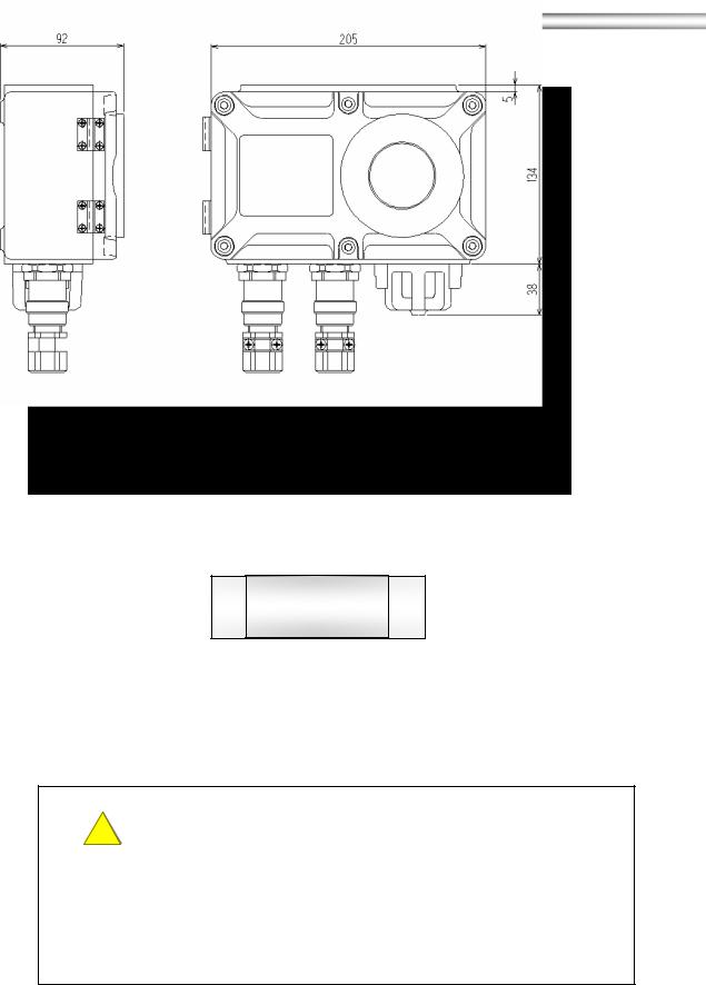
Overall view and name of each part
SD-705EC
“ ”WARNING:MAGNET
MODEL TC-7
RIKEN KEIKI
Control Key
WARNING
The control key used for adjustment is made from a powerful magnet. If it is brought nearer to a credit card, ID card, other magnetic products, this key may damage the stored data.
3

PT2E-1140
Display Part
MAINTENANCE/ESC switch Used for entering into the maintenance mode with the control key. And used for cancel the maintenance mode.
PW/TR light ……………… Illuminates continuously when the equipment is working
(power light). And flickers in the case of abnormality
in the equipment. |
|
AL1 light …………………… Illuminates when 1st |
alarm is activating. |
AL2 light ………………… Illuminates when 2nd |
alarm is activating. |
SKIP light………………… Illuminated when point skip is selected. And flickers in the maintenance mode.
AL-T(▲) switch ………… Used to increase the value with the control key.LCD ………………………. Indicates the gas concentration and error code.
AL/SET switch ……………… Used for confirmation of preset alarm level. And used for decision in the maintenance mode.
ZERO light … ………………Flickers in the zero adjustment mode.(Steady light when
the adjustment is over.)
SPAN light … ……………… Flickers in the span adjustment mode. .(Steady light when
the adjustment is over.)
mA light…………………… Illuminates with the current output indicated on the LCD (during maintenance)
mA (▼)switch ……………… Used for indicating current output on the LCD. And used to decrease the indication in the maintenance mode.
4
PT2E-1140
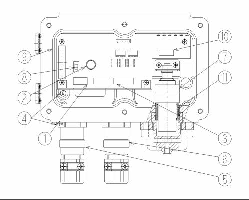
Internal View
Terminal plate………………… Connected to power source and 4-20mA signal output.Fuse…………………………… Fuse for power(0.5A)
Rely output terminal………… Connected to alarm relay output cable.Earth terminal………………… Used to make grounding
Cable inlet…………………… |
Used to lead the cable from the indicating alarm unit |
|
(With the pressure proof packing gland) |
Relay output and ………………Used to lead the cable from alarm relay output. |
|
communication cable inlet |
(With the pressure proof packing gland) |
Sensor………………………… Sensor connected. |
|
Power switch………………… |
Power ON/OFF switch. |
Seal packing……………………Used to protect equipment from water and dust. |
|
7p connector for detector…… Connected to cable for detector(sensor). |
|
(sensor) |
|
Packing……………………… |
Used to protect equipment from water and dust. |
5

PT2E-1140
Handling
Before Initial Use
On detecting a toxic gas leakage, this unit show the gas concentration on the LCD and outputs the gas concentration value in 4-20mA to the indicating alarm unit. When the concentration exceeds the preset level, the alarm contact activates.
In view of its duty, the gas detector must always be in the normal operation with the power supply ON. Therefore, it is essential to confirm its operation daily.
For the operation confirmation, refer to 4-1, Inspection Frequency and Items.
CAUTION
This detector may also be sensitive to gases other than objective gas. When the detector detects the gas and issues alarm, find out whether this is caused by the objective gas or other gases not covered by the detector.
Cautions for Installation and Handling
Never use the detector in the following places.
|
|
|
|
|
|
|
|
|
Place where the detector is splashed |
Place with vibration. |
|||||||
|
with water. |
|
||||||
|
(Use an optional drip-proof cover |
|
||||||
|
|
when the detector is to be installed |
|
|||||
|
|
out of doors.) |
|
|||||
|
|
|
|
|
|
|
|
|
|
|
|
|
|
|
|
|
|
|
|
|
|
|
|
|
|
|
|
|
|
|
|
|
|
|
|
Place with radio wave and noise.
Place where the detector is dropped or exposed to strong impact readily.
6
PT2E-1140
Caution
Be sure to use an optional drip-proof cover when the detector is to be installed out of doors.
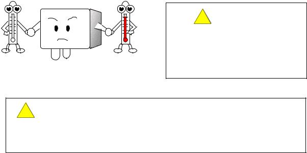
Place where the temperature is below 10 or +40 or more
CAUTION
When intending to open the lid, wait for 30 seconds or more after powered OFF and then, open the lid.
Cautions for System Engineering
Unstable power supply and noise may cause error of performance and alarm.
For the system to use this detector, it is required to make design based on this manual description.
(1) Stable power used
While the system gets stable at power on and power failure, the external output and alarm light may be on and the care for it must be taken. In such case, use the standby battery or take an appropriate action in the receiver side.
Supply the following power to this detector.
Power voltage |
:DC24V±10% |
Power failure tolerance time |
:Approx. 50msec or less |
|
(For power failure of more 50msec, it re-starts.) |
To warrant the continuous operation, install the standby battery outside.
(2)Noise measures according to installation circumstances.
Lightning Thunder surge measures
There is the problem point “Lightning(Thunder)” when installing the detector outside of factory. If the lightning is a huge generation source, the cable is a reception antenna and there is the case that cable connecting instrument is broken. It is impossible to prevent the generation of lightning. If the cable should put in metal tube, laid in the underground, it is impossible to prevent the inductive lightning surge generating from the thunder.
There is no complete countermeasure for it but the following method can be considered. Make the suitable treatment accordingly.
<Countermeasure by the lightning arrester(Cable safety retainer)>
There is the way to install the lightning arrester just before the field apparatus and the central control station. The position of the lightning arrester installation is at each point of cable laid out from the outdoor to the indoor.
The lightning arrester builds in the circuit to remove the surge voltage to be the source for the damage of field apparatus.
7

PT2E-1140
Power cable noise
Following is available to reduce the influence of electromagnetic induction noise and electrostatic induction noise from power cable.
<Isolation from power cable>
Use signal cable with a shield and ground.
Make electrical isolation such as using metal installation pipe for power cable, installing Isolation plate between power cable and electrostatic shield, and install them into exclusive metallic duct.
(3)Grounding the instrument
Lightning(Thunder) and etc make surge noise. To protect an instrument from surge noise, be sure to ground an instrument. Refer to 2-6. Wiring Method for details.
Maintenance Space
A certain maintenance space must be secured around the detector, so that the maintenance staff can perform the safe and correct maintenance and control operation of functions and performance. Pay due attention to secure this space during work plan and execution.
Maintenance space
8
PT2E-1140
Installation Method
(1) Install the detector body to a firm surface (wall surface, etc.) with M6 bolts. Use an optional mounting piece when installing the detector to the 2B pipe. (For the installation method, refer to Fig.1 through 4 below)
CAUTION
During installation, take care not to drop or throw the detector.
Otherwise, the strong impact may cause damage to the equipment
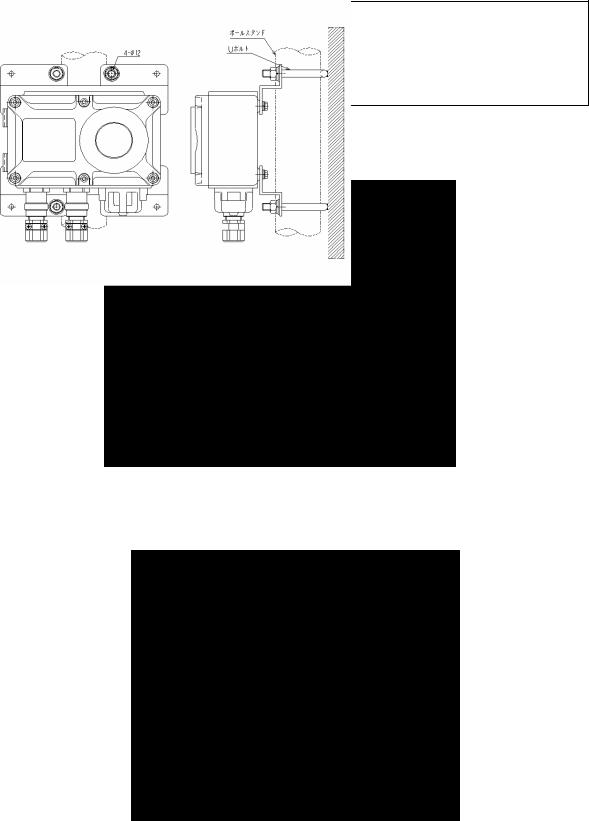
(a)Installation without using drip-proof cover
Installation to the wall (Fig.1)
Install to the wall after fixing the detector to the detector mounting piece with screw as shown above.
Installation to the 2B pipe(Fig.2)
Secure the detector to the detector mounting piece with screw and fix it to the U-bolt(M10) for 2B pipe as shown above.
9
PT2E-1140
(b) Installation using a drip-proof cover(option)
When installing the cover, slide it from the top to downward along the groove and fix it with the bottom fixture.
Installation to the wall Fig.3
Install to the wall after fixing the detector to the detector mounting piece with screw as
shown above.
Installation to the 2B pipe Fig.4
Secure the detector to the detector mounting piece with screw and fix it to the U-bolt(M10) for 2B pipe as shown above.
10

PT2E-1140
(2)Insert a packing gland(lower) →washer→packing→packing grand(upper) in this order onto the cable.
Lead the cable into the detector terminal box and attach a stick-type crimp terminal plate to the end of cable.
Cable finish O.D. |
Packing inside |
Washer inside |
|
diameter |
diameter |
||
|
|||
|
|
|
|
φ11 1 |
φ12 |
φ13 |
|
|
|
|
If cable finish O.D. does not meet with above packing gland, please contact with us.
(3)Loosen the hexagonal socket headed screws (6 points) of the detector and remove the lid, and the power terminal plate(3 points) and relay output terminal plate(6 points) appears. The power terminal plate(3P) has “+(DC24V)”, “-(DC24V)” and “Sig” marks from left to right. The “-(DC24V)” terminal is a common terminal (-) for the DC24V input and Sig output (DC4 20mA). Therefore, both the +(DC24V) and -(DC24V) terminals are for DC24V input and both the Sig and -(DC24V) are for DC4 0mA output.
DC24V input  4 20mA output
The relay output terminal plate (6P) has “First alarm relay output terminal (2P)”, “Second alarm relay output terminal (2P)” and trouble alarm relay terminal (2P).
|
|
|
|
|
|
|
|
|
|
|
|
Relay output |
Relay output |
Relay output for |
|||
for 1st alarm |
for 2nd alarm |
trouble alarm(option) |
|||
CAUTION
Be care not to damage the inner electronics circuit when making wiring construction.
<<Connection method for Terminal Plate>>Make the cable end naked.
(For length, refer to following “Length of naked wires.”
Insert the cable into plug of terminal and tighten it by minus screw driver.
After completion for connection of all cables, connect the plug onto the base of PCB.
11
Loading...