


OX-03
Table of contents
 Loading...
www.rkiinstruments.com
03 Series:
OX-03, CO-03, HS-03
Versions
Operator’s Manual
Part Number: 71-0304
Revision: C
Released: 9/26/18

03 Series Operator’s Manual
WARNING
Read and understand this instruction manual before operating
instrument. Improper use of the gas monitor could result in
bodily harm or death.
Periodic calibration and maintenance of the gas monitor is essen-
tial for proper operation and correct readings. Please calibrate
and maintain this instrument regularly! Frequency of calibration
depends upon the type of use you have and the sensor types.
Typical calibration frequencies for most applications are between
1 and 3 months, but can be required more often or less often
based on your usage.

03 Series Operator’s Manual Warranty
Warranty
RKI Instruments, Inc. warrants the OX-03 Single Gas Monitor sold by us to
be free from defects in materials, workmanship, and performance for a
period of two (2) years from the date of shipment from RKI Instruments,
Inc. and warrants the CO-03 and HS-03 Single Gas Monitors sold by us for
three (3) years from the date of shipment from RKI Instruments, Inc. This
includes the instrument and the original sensor. Replacement parts are
warranted for one (1) year from the date of their shipment from RKI
Instruments, Inc. Replacement sensors are warranted for two (2) years
from the date of their shipment from RKI Instruments, Inc. Any parts found
defective within their warranty period will be repaired or replaced, at our
option, free of charge. This warranty does not apply to those items, which
by their nature, are subject to deterioration or consumption in normal
service, and which must be cleaned, repaired, or replaced on a routine
basis. Examples of such items are as follows:
Warranty is voided by abuse including mechanical damage, alteration,
rough handling, or repair procedures not in accordance with the instruction
manual. This warranty indicates the full extent of our liability, and we are
not responsible for removal or replacement costs, local repair costs,
transportation costs, or contingent expenses incurred without our prior
approval.
THIS WARRANTY IS EXPRESSLY IN LIEU OF ANY AND ALL OTHER WARRANTIES
AND REPRESENTATIONS, EXPRESSED OR IMPLIED, AND ALL OTHER
OBLIGATIONS OR LIABILITIES ON THE PA RT OF RKI INSTRUMENTS, INC.
INCLUDING BUT NOT LIMITED TO THE WARRANTY OF MERCHANTABILITY OR
FITNESS FOR A PARTICULAR PURPOSE. IN NO EVENT SHALL RKI
I
NSTRUMENTS, INC. BE LIABLE FOR INDIRECT, INCIDENTAL, OR
CONSEQUENTIAL LOSS OR DAMAGE OF ANY KIND CONNECTED WITH THE USE
OF ITS PRODUCTS OR FAILURE OF ITS PRODUCTS TO FUNCTION OR OPERATE
PROPERLY.
This warranty covers instruments and parts sold to users only by
authorized distributors, dealers, and representatives as appointed by RKI
Instruments, Inc.
We do not assume indemnification for any accident or damage caused by
the operation of this gas monitor and our warranty is limited to replacement
of parts or our complete goods.
Absorbent cartridges
Filter elements, disks, or sheets
Pump diaphragms and valves

Table of Contents 03 Series Operator’s Manual
Table of Contents
Introduction . . . . . . . . . . . . . . . . . . . . . . . . . . . . . . . . . . . . . . . . . . . . . . . . . . . . . . . . . . 6
Specifications. . . . . . . . . . . . . . . . . . . . . . . . . . . . . . . . . . . . . . . . . . . . . . . . . . . . . . . . .7
Description . . . . . . . . . . . . . . . . . . . . . . . . . . . . . . . . . . . . . . . . . . . . . . . . . . . . . . . . . . . 9
Case . . . . . . . . . . . . . . . . . . . . . . . . . . . . . . . . . . . . . . . . . . . . . . . . . . . . . . . . . . . 9
Sensor Gasket, Sensor Membrane, and Charcoal Filter . . . . . . . . . . . . . . . . . . 10
Sensor. . . . . . . . . . . . . . . . . . . . . . . . . . . . . . . . . . . . . . . . . . . . . . . . . . . . . . . . . 10
LCD. . . . . . . . . . . . . . . . . . . . . . . . . . . . . . . . . . . . . . . . . . . . . . . . . . . . . . . . . . . 10
Control Buttons . . . . . . . . . . . . . . . . . . . . . . . . . . . . . . . . . . . . . . . . . . . . . . . . . . 11
Alarm LED. . . . . . . . . . . . . . . . . . . . . . . . . . . . . . . . . . . . . . . . . . . . . . . . . . . . . . 11
Buzzer. . . . . . . . . . . . . . . . . . . . . . . . . . . . . . . . . . . . . . . . . . . . . . . . . . . . . . . . . 11
Vibrator . . . . . . . . . . . . . . . . . . . . . . . . . . . . . . . . . . . . . . . . . . . . . . . . . . . . . . . . 11
IrDA Port . . . . . . . . . . . . . . . . . . . . . . . . . . . . . . . . . . . . . . . . . . . . . . . . . . . . . . . 12
Printed Circuit Boards . . . . . . . . . . . . . . . . . . . . . . . . . . . . . . . . . . . . . . . . . . . . . 12
Batteries . . . . . . . . . . . . . . . . . . . . . . . . . . . . . . . . . . . . . . . . . . . . . . . . . . . . . . . 12
Protective Rubber Boot . . . . . . . . . . . . . . . . . . . . . . . . . . . . . . . . . . . . . . . . . . . . 13
Alligator & Belt Clips . . . . . . . . . . . . . . . . . . . . . . . . . . . . . . . . . . . . . . . . . . . . . . 13
Start Up. . . . . . . . . . . . . . . . . . . . . . . . . . . . . . . . . . . . . . . . . . . . . . . . . . . . . . . . . . . . . 15
Start-up Procedure . . . . . . . . . . . . . . . . . . . . . . . . . . . . . . . . . . . . . . . . . . . . . . . 15
Performing a Fresh Air Adjustment . . . . . . . . . . . . . . . . . . . . . . . . . . . . . . . . . . . 22
Turning Off the 03 Series . . . . . . . . . . . . . . . . . . . . . . . . . . . . . . . . . . . . . . . . . . 23
Operation . . . . . . . . . . . . . . . . . . . . . . . . . . . . . . . . . . . . . . . . . . . . . . . . . . . . . . . . . . .24
Measuring Mode . . . . . . . . . . . . . . . . . . . . . . . . . . . . . . . . . . . . . . . . . . . . . . . . . 24
Adjusting the Buzzer Volume . . . . . . . . . . . . . . . . . . . . . . . . . . . . . . . . . . . . . . . 24
Display Mode, CO-03 and HS-03 . . . . . . . . . . . . . . . . . . . . . . . . . . . . . . . . . . . . 25
Display Mode, OX-03 . . . . . . . . . . . . . . . . . . . . . . . . . . . . . . . . . . . . . . . . . . . . . 27
Alarms. . . . . . . . . . . . . . . . . . . . . . . . . . . . . . . . . . . . . . . . . . . . . . . . . . . . . . . . . 30
Data Logging . . . . . . . . . . . . . . . . . . . . . . . . . . . . . . . . . . . . . . . . . . . . . . . . . . . . . . . . 35
03 Series User Setup Program . . . . . . . . . . . . . . . . . . . . . . . . . . . . . . . . . . . . . . . . . . 35
Calibration Mode . . . . . . . . . . . . . . . . . . . . . . . . . . . . . . . . . . . . . . . . . . . . . . . . . . . . . 36
Calibration Frequency. . . . . . . . . . . . . . . . . . . . . . . . . . . . . . . . . . . . . . . . . . . . . 36
Using Calibration Mode. . . . . . . . . . . . . . . . . . . . . . . . . . . . . . . . . . . . . . . . . . . . 36
Setting the Date and Time. . . . . . . . . . . . . . . . . . . . . . . . . . . . . . . . . . . . . . . . . . 38
Performing a Fresh Air Adjustment . . . . . . . . . . . . . . . . . . . . . . . . . . . . . . . . . . . 38

03 Series Operator’s Manual Table of Contents
Performing an Automatic Span Adjustment
(Zero Adjustment for OX-03) in A--CAL. . . . . . . . . . . . . . . . . . . . . . . . . . . . . . . . 39
Performing an Easy Span Adjustment (Zero Adjustment for OX-03) in E--CAL.. 44
Performing a Manual Span Adjustment (Zero Adjustment for OX-03) in M--CAL 50
Performing a Bump Test in BUMP . . . . . . . . . . . . . . . . . . . . . . . . . . . . . . . . . . . 53
Viewing the Instrument’s Firmware Version . . . . . . . . . . . . . . . . . . . . . . . . . . . . 59
Setup Mode. . . . . . . . . . . . . . . . . . . . . . . . . . . . . . . . . . . . . . . . . . . . . . . . . . . . . . . . . . 60
Using Setup Mode. . . . . . . . . . . . . . . . . . . . . . . . . . . . . . . . . . . . . . . . . . . . . . . . 60
Setting the Date and Time in DATE . . . . . . . . . . . . . . . . . . . . . . . . . . . . . . . . . . 62
Performing a Fresh Air Adjustment in AIR. . . . . . . . . . . . . . . . . . . . . . . . . . . . . . 62
Performing an Automatic Span Adjustment
(Zero Adjustment for OX-03) in A--CAL. . . . . . . . . . . . . . . . . . . . . . . . . . . . . . . . 62
Performing an Easy Span Adjustment (Zero Adjustment for OX-03) in E--CAL.. 62
Performing a Manual Span Adjustment (Zero Adjustment for OX-03) in M--CAL 63
Setting the Alarm Points . . . . . . . . . . . . . . . . . . . . . . . . . . . . . . . . . . . . . . . . . . . 63
Adjusting the Bump Test Limit Check Setting . . . . . . . . . . . . . . . . . . . . . . . . . . . 65
Setting the Password . . . . . . . . . . . . . . . . . . . . . . . . . . . . . . . . . . . . . . . . . . . . . 66
Maintenance . . . . . . . . . . . . . . . . . . . . . . . . . . . . . . . . . . . . . . . . . . . . . . . . . . . . . . . . . 68
Troubleshooting . . . . . . . . . . . . . . . . . . . . . . . . . . . . . . . . . . . . . . . . . . . . . . . . . 68
Replacing the Batteries. . . . . . . . . . . . . . . . . . . . . . . . . . . . . . . . . . . . . . . . . . . . 70
Replacing the Sensor . . . . . . . . . . . . . . . . . . . . . . . . . . . . . . . . . . . . . . . . . . . . . 72
Replacing the Sensor Membrane and Charcoal Filter . . . . . . . . . . . . . . . . . . . . 74
Parts List. . . . . . . . . . . . . . . . . . . . . . . . . . . . . . . . . . . . . . . . . . . . . . . . . . . . . . . . . . . . 76
WARNING: Understand this manual before operating the 03 Series.
Substitution of components may impair intrinsic safety.
To prevent ignition of a hazardous atmosphere, batteries
must only be changed in an area known to be
nonhazardous. This unit has not been tested in an
oxygen enrich ed atmosphere (above 21%).

6 • Introduction 03 Series Operator’s Manual
Introduction
Using an advanced microprocessor controlled detection system, the 03
Series Personal Single Channel Gas Monitor detects the presence of either
carbon monoxide (CO), hydrogen sulfide (H
2
S), or oxygen (O
2
). The 03
Series’ compact size and easy-to-use design make it ideally suited for a
wide range of applications, including sewage treatment plants, tunnels,
hazardous waste sites, petrochemical facilities, oil fields, mines, and
chemical plants. The 03 Series is even small enough to be placed
conveniently in a pocket. The 03 Series offers the following features:
• Compact design
• Fast, accurate response with backlit digital liquid crystal display (LCD)
• Visual, audible, and vibration alarms
• Microprocessor control for reliability, ease of use, and advanced
capabilities
• Resistance to RF (radio frequency) interference
• Datalogging including interval trend data and alarm trend data
• Peak, STEL, and TWA indication for CO-03 & HS-03
• Minimum and maximum indication for OX-03
• Over range alarm
• Gas, battery, sensor failure, and system failure alarms
• Over 3,000 hours operation on one set of alkaline batteries
• Rotatable alligator clip for “hands free” gas monitoring, belt clip optional
• CSA certification for intrinsic safety in Class I, Division I, Groups A, B,
C, and D hazardous atmospheres
WARNING: The 03 Series detects oxygen deficiency and elevated
levels of oxygen, carbon monoxide, and hydrogen
sulfide, all of which can be dangerous or life threatening.
When using the 03 Series, you must follow the
instructions and warnings in this manual to assure
proper and safe operation of the unit and to minimize the
risk of personal injury. Be sure to maintain and
periodically calibrate the 03 Series as described in this
manual.

03 Series Operator’s Manual Specifications • 7
Specifications
Table 1: 03 Series Specifications
CO-03 HS-03 OX-03
Target Gas Carbon Monoxide
(CO)
Hydrogen Sulfide
(H
2
S)
Oxygen
(O
2
)
Detection Range 0 to 500 ppm 0 to 100.0 ppm 0 to 40.0% vol.
Display Increment 1 ppm 0.5 ppm 0.1% vol.
Detection
Principle
Electro Chemical Electro Chemical Galvanic Cell
Alarm Points Low
High
TWA
STEL
25 ppm
50 ppm
25 ppm
200 ppm
Low
High
TWA
STEL
5.0 ppm
30.0 ppm
1.0 ppm
5.0 ppm
Low 19.5% vol.
(decreasing)
High 23.5% vol.
(increasing)
Sampling Method Diffusion Diffusion Diffusion
Response Time T90 in 30 seconds T90 in 30 seconds T90 in 20 seconds
Accuracy ± 5% of reading or
± 5 ppm CO
(whichever is
greater)
± 5% of reading or
± 2 ppm H
2
S
(whichever is
greater)
± 0.5% O
2
Indication Digital LCD
Safety/Regulatory
C US
186718
CSA classified, “C/US”, as Intrinsically Safe. Exia. Class I,
Groups A, B, C, & D. Temperature Code T3C.
Power Two AAA size alkaline batteries standard, Duracell MN2400 or
PC2400
Continuous
Operating Hours
At 25 °C: Over 3,000 hours, no alarms or backlighting
Case High-impact plastic, dust and weather proof
Standard
Accessories
• Rubber protective boot
• Alligator clip

8 • Specifications 03 Series Operator’s Manual
Optional
Accessories
• Calibration adapter
• Calibration kit
•Belt clip
• Wrist strap
• IrDA/USB cable for downloading data to computer
• Product CD, includes 03 Series Datalogging Program and
03 Series User Setup Program
Dimensions and
Weight
2.2” (54mm) W x 2.6” (67mm) H x 0.9” (24mm) D;
2.8 oz. (80 g)
Operating Temp. &
Humidity
-20°C to +50°C, 16 - 95% RH
(non condensing)
-20°C to +50°C,
0 - 95% RH (non
condensing)
Table 1: 03 Series Specifications
CO-03 HS-03 OX-03

03 Series Operator’s Manual Description • 9
Description
This section describes the components of the 03 Series.
Case
The 03 Series’ sturdy, high-impact plastic case is blue and consists of a
front and rear case. The case is suitable for use in many environmental
conditions, indoors and out. The unit is dust proof and weather resistant.
The front case has an LCD (liquid crystal display) that shows various
indications. Below the LCD are two black control buttons. The left button is
labeled “AIR” and the right button is labeled “POWER MODE”.
The buzzer opening is located in the top left corner of the front case. To the
right of the buzzer is the diffusion port for the sensor.
The alarm LED lens is located at the top of the front case.
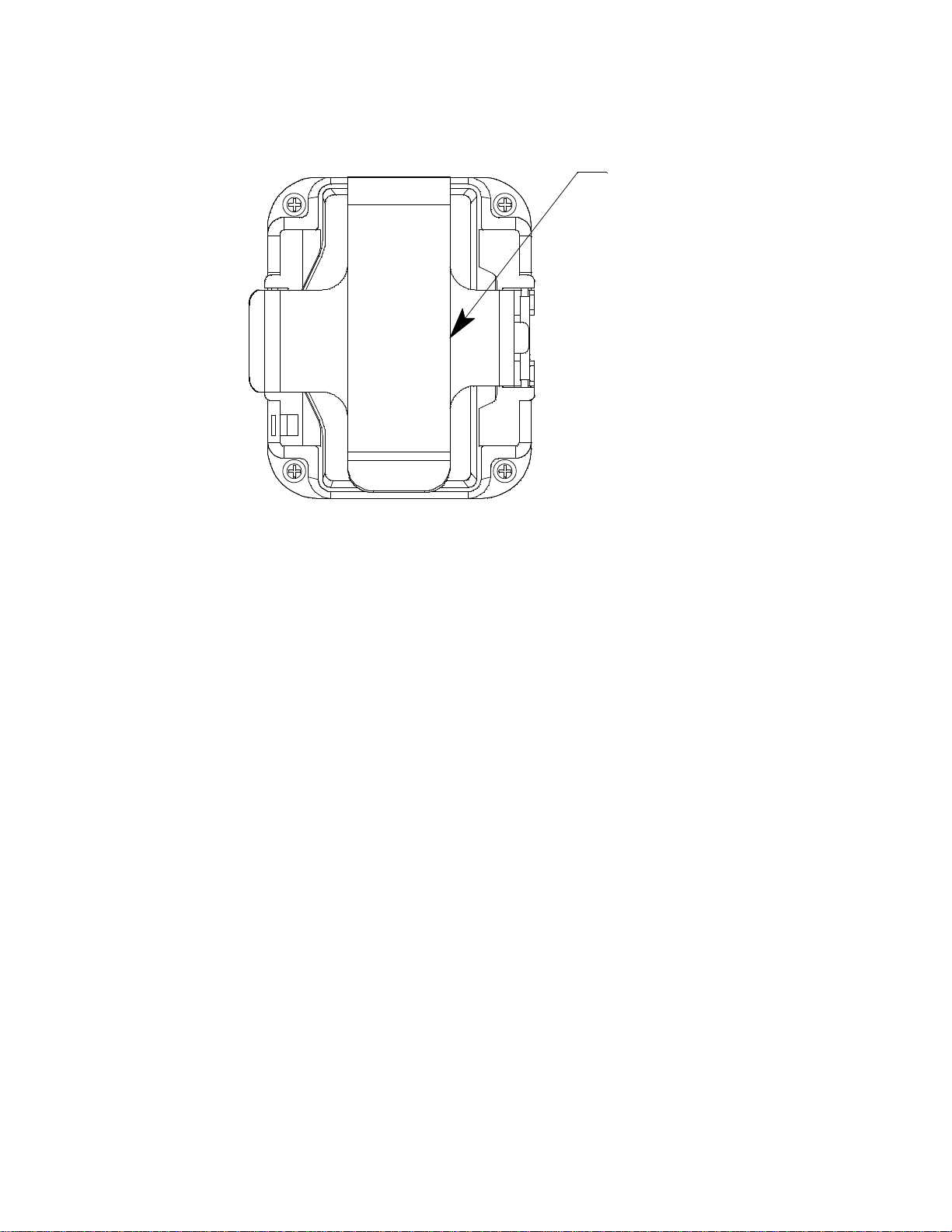
The battery compartment is located in the rear case. Access to the
compartment is accomplished by turning the captive battery cover screw
counterclockwise and by removing the battery cover.
There are two spring bars on the rear case. One is on the left and one is on
the right. They are the same type of spring bar that is used to retain a
watch band and are used to mount the alligator clip or optional belt clip.
A feature in the lower left corner of the rear case is used to install the
optional wrist strap.
Bat tery Cover Screw
Battery Cover
CO
AIR
CO-03
LCD
Buzzer Opening
IrDA Port
Control Buttons
Wrist St r ap
Connection
POWER
MODE
Dif f usion Port
Alarm LED
Figure 1: Components of the 03 Series

10 • Description 03 Series Operator’s Manual
Sensor Gasket, Sensor Membrane, and Charcoal Filter
The sensor membrane is a paper-like filter disk that is held in place by the
sensor gasket and fits into a recessed area on the inside of the front case.
The sensor membrane covers the diffusion port and protects the sensor
from dirt and moisture. The sensor membrane should be inspected
periodically and replaced if contaminated by dirt or moisture. See
“Replacing the Sensor Membrane and Charcoal Filter” on page 74 for
sensor membrane replacement instructions.
The CO-03 includes a charcoal filter disk which is located in the sensor
gasket. The charcoal filter disk removes gases from the sampled air that
will cause a response on the CO sensor such as H
2
S and certain
hydrocarbons. If false or elevated CO readings are noticed, especially in
the presence of H
2
S, change the charcoal filter disk. See “Replacing the
Sensor Membrane and Charcoal Filter” on page 74 for replacement
instructions.
Sensor
The 03 Series uses either an oxygen, CO, or H
2
S sensor. The sensor is
protected by the white sensor membrane which is held in place by the
sensor gasket. The sensor membrane allows ambient air to diffuse past it
to the sensor. The three sensors used in the three 03 Series models use
different detection principles as described below.
Oxygen Sensor
The oxygen sensor is a galvanic type of sensor. A membrane covers the
cell and allows gas to diffuse into the cell at a rate proportional to the partial
pressure of oxygen. The oxygen reacts in the cell and produces a voltage
proportional to the concentration of oxygen. The voltage is measured by
the 03 Series’ circuitry, converted to a measurement of gas concentration,
and displayed on the LCD.
CO and H
2
S Sensors
The CO and H
2
S sensors are electrochemical sensors that consist of two
precious metal electrodes in an acid electrolyte. A gas permeable
membrane covers the sensor face and allows gas to diffuse into the
electrolyte. The gas reacts in the sensor and produces a current
proportional to the concentration of the target gas. The current is amplified
by the 03 Series’ circuitry, converted to a measurement of gas
concentration, and displayed on the LCD.
LCD
The LCD is visible through the front case. When the 03 Series is in
Measuring Mode, the target gas concentration, battery condition, and
alarm indications are displayed on the LCD. Various other items are

03 Series Operator’s Manual Description • 11
displayed when the LCD is in other modes, such as Calibration Mode.
When either of the two control buttons are pressed, the LCD backlight
comes on for 20 seconds.
Control Buttons
Below the LCD are two control buttons: POWER MODE and AIR. The
POWER MODE button turns the 03 Series on and off. The functions
performed by the control buttons are summarized in the following table:
Alarm LED
The 03 Series has one red alarm LED. It alerts you to gas, low battery, and
sensor failure alarms. The alarm LED is located at the top of the front case
beneath a clear plastic lens.
Buzzer
A solid-state electronic buzzer is mounted inside the 03 Series. An opening
in the top left corner of the front case allows the buzzer’s sound to emanate
from the case. The buzzer sounds for gas alarms, unit malfunctions, and
the dead battery alarm. It also serves as an indicator during normal use of
the various LCD display options.
Vibrator
A vibrating motor (vibrator) is mounted inside the 03 Series. The vibrator
vibrates momentarily during the power-up sequence and for gas alarms.
Table 2: 03 Series Control Buttons
Button Function
POWER MODE
• Turns the unit on and off.
• Turns the LCD back light on.
• Resets the alarm circuit (gas alarms).
• Enters Display Mode.
• Enters Calibration Mode with the AIR button.
• Enters Setup Mode with the AIR button.
AIR
• Turns the LCD back light on.
• Adjusts LCD reading when the fresh air
adjustment is performed.
• Enters Calibration Mode with the POWER MODE
button.
• Enters Setup Mode with the POWER MODE
button.
• Increases or decreases settings when the unit is in
Calibration Mode or Setup Mode.

12 • Description 03 Series Operator’s Manual
IrDA Port
An infrared (IR) communications port is located just to the left of the alarm
LED at the top of the front case beneath the clear lens. The data
transmitted through the port is in standard IrDA protocol. A computer’s
infrared port or an IrDA/USB cable connected to a computer’s USB port
can be used to download data saved by the 03 Series to a computer using
the 03 Series Data Logger Management Program. See the 03 Series Data
Logger Management Program operator’s manual for data logging and
downloading instructions.
Printed Circuit Board
The primary function of the 03 Series’ printed circuit board is to amplify the
signal sent to it from the sensor, convert the signal to a meaningful
measurement of gas concentration, display the gas concentration on the
LCD, store STEL, TWA, and peak gas readings, and activate the alarm
circuit if an alarm point has been reached. It monitors battery level, battery
failure, and sensor failure. It also controls various operating modes of the
unit.
NOTE: The printed circuit board contains no user serviceable parts.
Batteries
Two AAA-size alkaline batteries run the 03 Series. At 25°C the alkaline
batteries last at least 3,000 hours. The battery icon on the LCD shows
remaining battery life.
When the 03 Series detects low battery voltage, a low battery warning is
activated. When battery voltage is too low for normal operation, the 03
Series sounds a dead battery alarm.
The alkaline batteries can be replaced by removing the battery cover on
the rear case. Turn the captive battery cover screw counterclockwise to
release the door. See “Replacing the Batteries” on page 70 for detailed
battery changing instructions.
WARNING: To prevent ignition of a hazardous atmosphere, batteries
must only be changed in an area known to be
nonhazardous.
AVERTISSEMENT:Pour éviter l’inflammation d’une atmosphère
dangereuse, les batteries doivent uniquement être
modifiés ou facturés dans une zone connue comme non
dangereuse.

03 Series Operator’s Manual Description • 13
NOTE: Use of batteries not specified by RKI Instruments, Inc. will void the
CSA classification and may void the warranty. See “Replacing the
Batteries” on page 70.
Protective Rubber Boot
A protective rubber boot is installed over the 03 Series.
Figure 2: Rubber Boot
Alligator and Belt Clips
The 03 Series is available with two types of clips: the alligator clip
(standard) and the belt clip (optional). The alligator clip is shown in Figure 3
below. The alligator clip can be used to attach the 03 Series to clothing or a
belt. Teeth in the clip’s jaws prevent the unit from slipping off. The clip can
be rotated in 45 degree turns if necessary.
Figure 3: Alligator Clip
Side Front
Open
Alligator Clip
Closed
14 • Description 03 Series Operator’s Manual
The belt clip is shown in Figure 4 below and is used to easily clip the 03
Series on a belt.
Figure 4: Belt Clip
Belt Clip

03 Series Operator’s Manual Start Up • 15
Start Up
This section explains how to start up the 03 Series and to get it ready for
operation.
NOTE: The screens shown in this section are for a CO-03. If you are
using a different version of the 03 Series, your instrument screen
will vary slightly from those shown below.
Start-up Procedure
1. Press and briefly hold down the POWER MODE button. The backlight
will turn on and all the display segments will turn on. Release the button
when you hear a beep.
2. The vibrator vibrates and the alarm light flashes momentarily.
3. The initial startup screen depends on how Bump Fail Behavior is set.
This parameter along with the Cal. Limit Display and Cal. Limit Check
parameters mentioned in Step 5 and the Auto Zero Adjustment
parameter mentioned in Step 12 below cannot be set using the 03
Series’ instrument menus, but are set using the 03 Series User Setup
Program. See the 03 Series User Setup Program Operator’s Manual for
information regarding changing various instrument parameters that are
not available for adjustment in the instrument’s operating modes.
•If Bump Fail Behavior is set to None (factory setting) or if it is set to
Can Not Use and the most recently performed bump test passed,
proceed to Step 5.
•If Bump Fail Behavior is set to Can Not Use and the most recently
performed bump test failed, the following screen will appear.
The instrument cannot be used until a successful bump test or
calibration is performed. See “Calibration Mode” on page 36 for
instructions.
4. If Cal. Limit Display is set to Off, proceed to Step 6.
C.AL
FAIL

16 • Start Up 03 Series Operator’s Manual
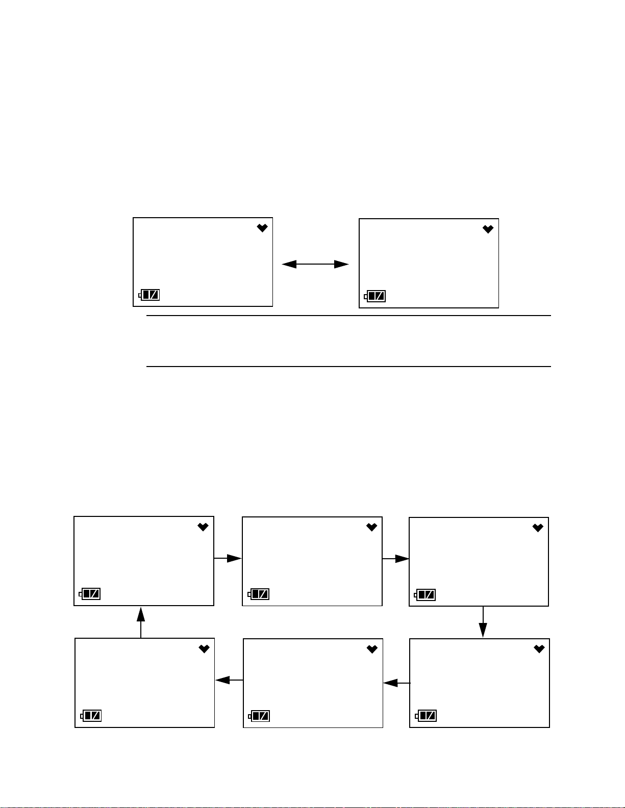
5. If Cal. Limit Display is set to On (factory setting), the screen that
appears next depends on how Cal. Limit Check is set.
• If the unit is due for calibration and Cal. Limit Check is set to
Confirm to use (factory setting), then the following screen sequence
will occur.
The alarm LED and buzzer will pulse several times.
To continue the startup sequence without performing a calibration,
press and release the AIR button. Continue to Step 6.
To perform a calibration, press and release the POWER MODE
button. Depending on the value entered into the One Touch Cal
Time parameter using the 03 Series User Setup Program, the
instrument will display either the A--CAL menu item or the E--CAL
menu item in Calibration Mode. See “Calibration Mode” on page 36
for instructions.
WARNING: You must press either the POWER MODE or AIR button to
continue. If you do not press a button, the buzzer will
continue to beep and the LED will continue to flash for 6
seconds every 5 seconds.
MODE
C.LIMIT
CAL
YES
C.LIMIT
CAL
AIR
C.LIMIT
CAL
NO
C.LIMIT
CAL
C.LIMIT
CAL
C.LIMIT
CAL

03 Series Operator’s Manual Start Up • 17
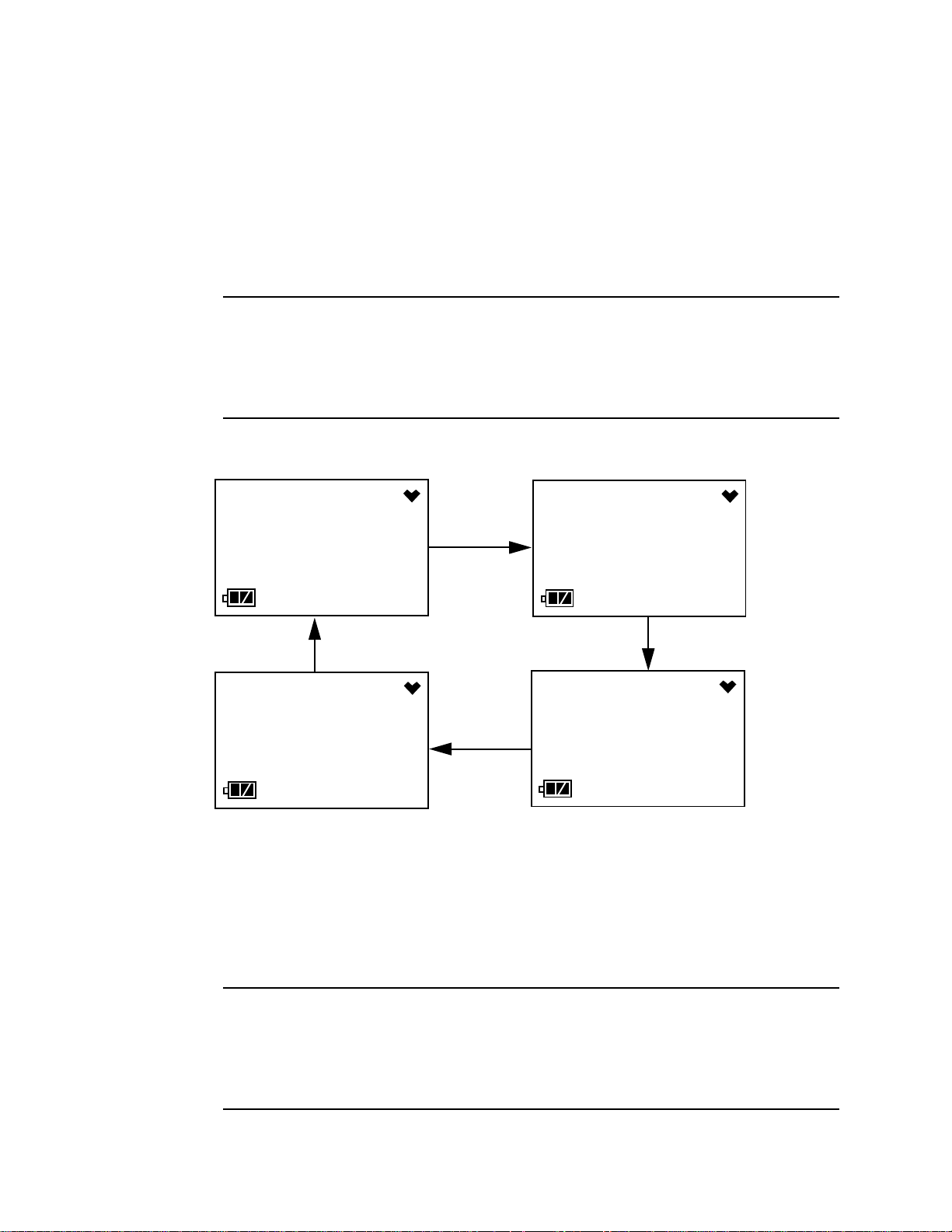
• If the unit is due for calibration and Cal. Limit Check is set to Can’t
use, then the following screen sequence will occur.
The alarm LED and buzzer will pulse several times. Press and
release the POWER MODE button. Depending on the value entered
into the One Touch Cal Time parameter using the 03 Series User
Setup Program, the instrument will display either the A--CAL menu
item or the E--CAL menu item in Calibration Mode. The above
screen will remain on the display until the unit is either turned off or
Calibration Mode is entered. The 03 Series cannot be used until a
complete calibration has been performed either by selecting A--
CAL, E--CAL, or M--CAL in the Calibration Mode menu. See
“Performing an Automatic Span Adjustment (Zero Adjustment for
OX-03) in A--CAL” on page 39, “Performing an Easy Span
Adjustment (Zero Adjustment for OX-03) in E--CAL” on page 44, or
“Performing a Manual Span Adjustment (Zero Adjustment for OX-
03) in M--CAL” on page 50 for calibration instructions.
WARNING: You must perform a successful calibration in order to
continue to normal operation. If you do not perform a
successful calibration, the screen sequence will
continue, the buzzer will continue to beep, and the LED
will continue to flash for 6 seconds every 5 seconds and
the unit will not enter normal operation.
• If a calibration is due and Cal. Limit Check is set to None, the
sequence below will occur twice.
MODE
C.LIMIT
FAIL
YES
C.LIMIT
FAIL
C.LIMIT
FAIL
MODE
C.LIMIT
YES
C.LIMIT
C.LIMIT
0d 0d
0d
18 • Start Up 03 Series Operator’s Manual
Press and release the POWER MODE button during this time to go
to the A--CAL or E--CAL menu item in Calibration Mode depending
on the value entered into the One Touch Cal Time parameter of the
03 Series User Setup Program. If no button is pressed, the
instrument will continue with the warmup sequence in Step 6 once
the sequence shown above has finished.
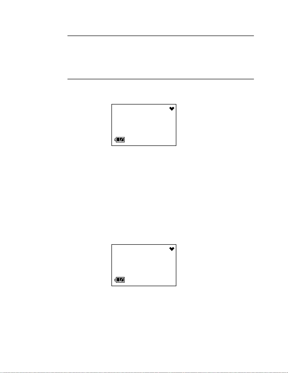
• If calibration is not due, then the following screen appears for a few
seconds indicating when the next calibration is due. “NEXT” and
“CAL” alternate on the bottom of the screen.
NOTE: The following screens in Step 6 only appear if Bump Test Limit
Display is set to On using the 03 Series User Setup Program. The
standard factory setting for this function is Off.
6. If Bump Test Limit Display is set to Off (factory setting), proceed to
Step 8.
7. If Bump Test Limit Display is set to On using the 03 Series User Setup
Program, the next screen will depend on how Bump Test Limit Check
is set in Setup Mode or using the 03 Series User Setup Program.
• If the unit is due for bump testing and Bump Test Limit Check is set
to Confirm to use (factory setting), then the following screen
sequence will occur.
CAL.
14. 2.17
180d
NEXT
14. 2.17
180d
BUMP
teSt
YES
NOW
teSt
MODE
BUMP
teSt
NOW
teSt
NO
BUMP
teSt
AIR
NOW
teSt
03 Series Operator’s Manual Start Up • 19
The alarm LED and buzzer will pulse several times.
To continue the startup sequence without performing a bump test,
press and release the AIR button. Continue to Step 8.
To perform a bump test, press and release the POWER MODE
button. The instrument will display the BUMP menu item in
Calibration Mode. See “Performing a Bump Test in BUMP” on
page 53 for instructions.
WARNING:You must press either the POWER MODE or AIR button to
continue. If you do not press a button, the screen
sequence will continue, the buzzer will continue to beep
and the LED will continue to flash for 6 seconds every 5
seconds.
• If the unit is due for bump testing and Bump Test Limit Check is set
to Can’t use, then the following screen sequence will occur.
The alarm LED and buzzer will pulse several times. Press and
release the POWER MODE button to go to the BUMP menu item in
Calibration Mode. The above screens will remain on the display until
the unit is either turned off or Calibration Mode is entered. The 03
Series cannot be used until a bump test has been performed. See
“Performing a Bump Test in BUMP” on page 53 for bump test
instructions.
WARNING:You must perform a successful bump test in order to
continue to normal operation. If you do not perform a
successful bump test, the buzzer will continue t o beep and
the LED will continue to flash for 6 seconds every 5
seconds and the unit will not enter normal operation.
BUMP
FAIL
YES
NOW
FAIL
MODE
BUMP
FAIL
NOW
FAIL

20 • Start Up 03 Series Operator’s Manual
• If a bump test is due and Bump Test Limit Check is set to None,
the sequence below will occur twice.
Press and release the POWER MODE button during this time to go
to the BUMP menu item in Calibration Mode. If no button is pressed,
the instrument will continue with the warmup sequence in Step 8
once the sequence shown above has finished.
NOTE: If a successful calibration is performed, the next bump test date is
reset and starts over even though a bump test was not performed.
• If bump testing is not due, then the following screen appears for a
few seconds indicating when the next bump test is due. “NEXT” and
“BUMP” alternate on the bottom of the screen.
8. The Date/Time Screen appears for a few seconds.
This screen displays the current date and time.
9. The Battery Voltage Screen appears for a few seconds.
MODE
BUMP
YES
BUMP
BUMP
0d 0d
0d
BUMP
14. 2.17
180d
NEXT
14. 2.17
180d
8:20
2014
1.31
bAtt
3.0
V

03 Series Operator’s Manual Start Up • 21
The screen displays the current battery voltage.
CAUTION: If the unit gives a low batt ery warning or dead battery alarm,
change the alkaline batteries before using the unit.
10.The display then indicates the following items for about a second each:
• Full scale value
• Warning setpoint (low gas alarm)
• Alarm setpoint (high gas alarm)
• STEL alarm setpoint (CO and H2S only)
• TWA alarm setpoint (CO and H2S only)
11. If the 03 Series experiences a sensor failure during start up, the
following screen will appear.
The instrument cannot be used if a sensor failure occurs. Replace the
failed sensor.
12. If Auto Zero Adjustment is set to On (factory setting is Off), then the
03 Series will perform an automatic fresh air adjustment.
If the fresh air adjustment is successful, the unit will proceed to Normal
Mode. If the sensor fails the air adjustment, the screen will indicate the
failure. If a failure occurs, press and release the POWER MODE button
to proceed to Normal Mode. Replace the failed sensor as soon as
possible.
SENSOR
FAIL
ZERO
AUTO
- - - -
22 • Start Up 03 Series Operator’s Manual
WARNING: If the Auto Zero Adjustment feature is turned on, mak e
sure that you start-up the 03 Series in a known fresh air
environment, an environment free of combustible or toxic
gasses and of normal oxygen content, 20.9%. If you do
not start-up the unit in a fresh air environment, the fresh
air adjustment will not be accurate.
13.The 03 Series is now operating in Measuring Mode and monitoring for
gas. The Normal Operation Screen appears and the instrument beeps
once.
The gas concentration of the target gas is displayed along with the
battery charge level in the lower left corner. The heart symbol displayed
in the upper right corner flashes while the instrument is functioning
properly. If it disappears or is steadily on, the unit is experiencing a
microprocessor error. The backlight turns off after 20 seconds.
Performing a Fresh Air Adjustment
Before using the 03 Series, set the fresh air reading. Performing this
adjustment ensures accurate gas readings in the monitoring environment.
1. Find a fresh air environment of normal oxygen content (20.9%) that is
free of toxic or combustible gases.
2. With the unit on and in Measuring Mode, press and hold the AIR button.
The LCD displays “hold” prompting you to hold the AIR button.
CO
ppm
0
AIR
HOLD
- - - -

03 Series Operator’s Manual Start Up • 23
3. Release the AIR button when the following screen appears. The unit
will set the reading to 0 ppm (20.9% for the OX-03) and return to
Measuring Mode.
Turning Off the 03 Series
1. Press and hold the POWER MODE button for about five seconds to
turn off the unit. The buzzer will pulse while the POWER MODE button
is being pressed before the unit turns off.
2. Release the button when the LCD is blank. The unit is off.
NOTE: If Power Off Password Protection is turned On (factory setting is
Off) using the 03 Series User Setup Program, a password is
required to turn the 03 Series off. When the password screen
appears, adjust each digit with the AIR button and press and
release the POWER MODE button to move on to the next digit.
Once the password has been entered, the instrument will shut off
and the LCD will be blank.
ADJ
- - - -

24 • Operation 03 Series Operator’s Manual
Operation
This section describes Measuring Mode, setting the buzzer volume,
Display Mode, and alarm indications.
NOTE: The screens shown in this section are for a CO-03. If you are
using a different version of the 03 Series, your instrument screen
will vary slightly from those shown below.
Measuring Mode
In Measuring Mode, the battery level and target gas concentration are
displayed on the LCD. The battery icon has three bars visible when the
batteries have a full charge. As the battery charge decreases, the bars will
gradually disappear, one by one. The heart symbol displayed in the upper
right corner flashes while the instrument is functioning properly. If it
disappears or is steadily on, the unit is experiencing a microprocessor
error.
The target gas concentration is displayed in the middle of the LCD. On the
CO-03, CO is displayed in parts per million (ppm). On the HS-03, H
2
S is
displayed in ppm. On the OX-03, oxygen is displayed as volume percent.
Adjusting the Buzzer Volume
The buzzer volume on the 03 Series can be adjusted while in Measuring
Mode if Buzzer Volume Selection is set to On (factory setting is Off). The
Buzzer Volume Selection setting can be adjusted using the 03 Series
User Setup Program. The default buzzer volume setting is HI. If it is
changed to LO, the setting will revert back to HI the next time the
instrument is turned on.
1. Make sure the 03 Series is in the Measuring Mode Normal Operation
screen.
2. Press and hold the POWER MODE and AIR buttons simultaneously.
NOTE: To avoid entering Display Mode, press the AIR button slightly
sooner than pressing the POWER MODE button.
Release both buttons when the instrument starts simulating an alarm
CO
ppm
0
Loading...