


GX-2012
Operator’s Manual
Part Number: 71-0239RK
Revision: H
Released: 3/17/14
www.rkiinstruments.com
WARNING
Read and understand this instruction manual before operating instrument. Improper use of the gas monitor could result in bodily harm or death.
Periodic calibration and maintenance of the gas monitor is essential for proper operation and correct readings. Please calibrate and maintain this instrument regularly! Frequency of calibration depends upon the type of use you have and the sensor types. Typical calibration frequencies for most applications are between 1 and 3 months, but can be required more often or less often based on your usage.
GX-2012 Operator’s Manual

Warranty
RKI Instruments, Inc. warrants the GX-2012 sold by us to be free from defects in materials, workmanship, and performance for a period of two years from the date of shipment from RKI Instruments, Inc. This includes the instrument and the original sensors. Replacement parts are warranted for 1 year from the date of their shipment from RKI Instruments, Inc. except for replacement sensors which are warranted for 2 years. Any parts found defective within their warranty period will be repaired or replaced, at our option, free of charge. This warranty does not apply to those items which by their nature are subject to deterioration or consumption in normal service, and which must be cleaned, repaired, or replaced on a routine basis. Examples of such items are:
Absorbent cartridges
Filter elements, disks, or sheets
Pump diaphragms and valves
Warranty is voided by abuse including mechanical damage, alteration, rough handling, or repair procedures not in accordance with the instruction manual. This warranty indicates the full extent of our liability, and we are not responsible for removal or replacement costs, local repair costs, transportation costs, or contingent expenses incurred without our prior approval.
THIS WARRANTY IS EXPRESSLY IN LIEU OF ANY AND ALL OTHER WARRANTIES AND REPRESENTATIONS, EXPRESSED OR IMPLIED, AND ALL OTHER OBLIGATIONS OR LIABILITIES ON THE PART OF RKI INSTRUMENTS, INC. INCLUDING BUT NOT LIMITED TO THE WARRANTY OF MERCHANTABILITY OR FITNESS FOR A PARTICULAR PURPOSE. IN NO EVENT SHALL RKI INSTRUMENTS, INC. BE LIABLE FOR INDIRECT, INCIDENTAL, OR CONSEQUENTIAL LOSS OR DAMAGE OF ANY KIND CONNECTED WITH THE USE OF ITS PRODUCTS OR FAILURE OF ITS PRODUCTS TO FUNCTION OR OPERATE PROPERLY.
This warranty covers instruments and parts sold to users only by authorized distributors, dealers, and representatives as appointed by RKI Instruments, Inc.
We do not assume indemnification for any accident or damage caused by the operation of this gas monitor and our warranty is limited to replacement of parts or our complete goods.
Warranty |
GX-2012 Operator’s Manual |

Table of Contents
Chapter 1: Introduction . . . . . . . . . . . . . . . . . . . . . . . . . . . . . . . . . . . . 1
Overview . . . . . . . . . . . . . . . . . . . . . . . . . . . . . . . . . . . . . . . . . . . . . . . . . . . . 1
About the GX-2012 . . . . . . . . . . . . . . . . . . . . . . . . . . . . . . . . . . . . . . . . . . . . 1
Specifications . . . . . . . . . . . . . . . . . . . . . . . . . . . . . . . . . . . . . . . . . . . . . . . . . 3
About This Manual . . . . . . . . . . . . . . . . . . . . . . . . . . . . . . . . . . . . . . . . . . . . 4
Chapter 2: Description . . . . . . . . . . . . . . . . . . . . . . . . . . . . . . . . . . . . . 5
Overview . . . . . . . . . . . . . . . . . . . . . . . . . . . . . . . . . . . . . . . . . . . . . . . . . . . . 5
Instrument Description. . . . . . . . . . . . . . . . . . . . . . . . . . . . . . . . . . . . . . . . . . 5
Case . . . . . . . . . . . . . . . . . . . . . . . . . . . . . . . . . . . . . . . . . . . . . . . . . . . 6
Sensors. . . . . . . . . . . . . . . . . . . . . . . . . . . . . . . . . . . . . . . . . . . . . . . . . 6
LCD . . . . . . . . . . . . . . . . . . . . . . . . . . . . . . . . . . . . . . . . . . . . . . . . . . . 8
Control Buttons . . . . . . . . . . . . . . . . . . . . . . . . . . . . . . . . . . . . . . . . . . 9
Printed Circuit Boards. . . . . . . . . . . . . . . . . . . . . . . . . . . . . . . . . . . . . 9
Alarm LED Arrays. . . . . . . . . . . . . . . . . . . . . . . . . . . . . . . . . . . . . . . . 9
Infrared Communications Port . . . . . . . . . . . . . . . . . . . . . . . . . . . . . . 9
Buzzer . . . . . . . . . . . . . . . . . . . . . . . . . . . . . . . . . . . . . . . . . . . . . . . . 10
Vibrator . . . . . . . . . . . . . . . . . . . . . . . . . . . . . . . . . . . . . . . . . . . . . . . 10
Batteries. . . . . . . . . . . . . . . . . . . . . . . . . . . . . . . . . . . . . . . . . . . . . . . 10
Pump . . . . . . . . . . . . . . . . . . . . . . . . . . . . . . . . . . . . . . . . . . . . . . . . . 11
Flow Chamber . . . . . . . . . . . . . . . . . . . . . . . . . . . . . . . . . . . . . . . . . . 11
Sensors and Filters . . . . . . . . . . . . . . . . . . . . . . . . . . . . . . . . . . . . . . 11
Inlet Filter Holder . . . . . . . . . . . . . . . . . . . . . . . . . . . . . . . . . . . . . . . 11
Standard Accessories . . . . . . . . . . . . . . . . . . . . . . . . . . . . . . . . . . . . . . . . . . 12
Tapered Rubber Nozzle . . . . . . . . . . . . . . . . . . . . . . . . . . . . . . . . . . . 12
Belt Clip . . . . . . . . . . . . . . . . . . . . . . . . . . . . . . . . . . . . . . . . . . . . . . . 12
Wrist Strap . . . . . . . . . . . . . . . . . . . . . . . . . . . . . . . . . . . . . . . . . . . . . 12
Sample Hose & 10 Inch Probe. . . . . . . . . . . . . . . . . . . . . . . . . . . . . . 12
Optional Accessories . . . . . . . . . . . . . . . . . . . . . . . . . . . . . . . . . . . . . . . . . . 13
Charging Stations . . . . . . . . . . . . . . . . . . . . . . . . . . . . . . . . . . . . . . . 13
Optional Probes. . . . . . . . . . . . . . . . . . . . . . . . . . . . . . . . . . . . . . . . . 16
Purge Tee Fitting . . . . . . . . . . . . . . . . . . . . . . . . . . . . . . . . . . . . . . . . 18
External Dilution Fitting . . . . . . . . . . . . . . . . . . . . . . . . . . . . . . . . . . 18
GX-2012 Operator’s Manual |
Table of Contents |
Chapter 3: Using the GX-2012 in Normal Mode . . . . . . . . . . . . . . . 19
Overview . . . . . . . . . . . . . . . . . . . . . . . . . . . . . . . . . . . . . . . . . . . . . . . . . . . 19 Start Up, Normal Mode . . . . . . . . . . . . . . . . . . . . . . . . . . . . . . . . . . . . . . . . 19
Turning On the GX-2012, Normal Mode Only . . . . . . . . . . . . . . . . . 19 Turning On the GX-2012 in Normal With All Modes Active . . . . . . . 25 Performing a Fresh Air Adjustment, Normal Mode . . . . . . . . . . . . . 27 Turning Off the GX-2012, Normal Mode. . . . . . . . . . . . . . . . . . . . . . 28
Measuring Mode, Normal Operation . . . . . . . . . . . . . . . . . . . . . . . . . . . . . . 28
Monitoring an Area . . . . . . . . . . . . . . . . . . . . . . . . . . . . . . . . . . . . . . 28 Using Optional Probes and Fittings . . . . . . . . . . . . . . . . . . . . . . . . . 29 Combustible Gas Detection . . . . . . . . . . . . . . . . . . . . . . . . . . . . . . . . 31 Snap Log Mode . . . . . . . . . . . . . . . . . . . . . . . . . . . . . . . . . . . . . . . . . 33
Measuring Mode, Alarms . . . . . . . . . . . . . . . . . . . . . . . . . . . . . . . . . . . . . . 36
Alarm Indications . . . . . . . . . . . . . . . . . . . . . . . . . . . . . . . . . . . . . . . 36 Resetting and Silencing Alarms . . . . . . . . . . . . . . . . . . . . . . . . . . . . . 38 Responding to Alarms . . . . . . . . . . . . . . . . . . . . . . . . . . . . . . . . . . . . 39
Inert Mode . . . . . . . . . . . . . . . . . . . . . . . . . . . . . . . . . . . . . . . . . . . . . . . . . . 42
Alarms . . . . . . . . . . . . . . . . . . . . . . . . . . . . . . . . . . . . . . . . . . . . . . . . 42 Start Up and Operation . . . . . . . . . . . . . . . . . . . . . . . . . . . . . . . . . . . 42
Display Mode. . . . . . . . . . . . . . . . . . . . . . . . . . . . . . . . . . . . . . . . . . . . . . . . 43
HC Range Screen. . . . . . . . . . . . . . . . . . . . . . . . . . . . . . . . . . . . . . . . 44 Peak Screen . . . . . . . . . . . . . . . . . . . . . . . . . . . . . . . . . . . . . . . . . . . . 44 STEL Screen. . . . . . . . . . . . . . . . . . . . . . . . . . . . . . . . . . . . . . . . . . . . 45 TWA Screen . . . . . . . . . . . . . . . . . . . . . . . . . . . . . . . . . . . . . . . . . . . . 45 Alarm Points Screen . . . . . . . . . . . . . . . . . . . . . . . . . . . . . . . . . . . . . 46 Operation Time Screen . . . . . . . . . . . . . . . . . . . . . . . . . . . . . . . . . . . 47 Date/Time Screen . . . . . . . . . . . . . . . . . . . . . . . . . . . . . . . . . . . . . . . . 48 Remaining Log Time Screen . . . . . . . . . . . . . . . . . . . . . . . . . . . . . . . 51 Clear Data Logger Screens . . . . . . . . . . . . . . . . . . . . . . . . . . . . . . . . 49 Pump Off Screen . . . . . . . . . . . . . . . . . . . . . . . . . . . . . . . . . . . . . . . . 50 User ID Screen. . . . . . . . . . . . . . . . . . . . . . . . . . . . . . . . . . . . . . . . . . 51 Station ID Screen . . . . . . . . . . . . . . . . . . . . . . . . . . . . . . . . . . . . . . . . 52 Snap Logging Screen . . . . . . . . . . . . . . . . . . . . . . . . . . . . . . . . . . . . . 53 Peak Bar Select Screen . . . . . . . . . . . . . . . . . . . . . . . . . . . . . . . . . . . 55
Datalogging . . . . . . . . . . . . . . . . . . . . . . . . . . . . . . . . . . . . . . . . . . . . . . . . . 56 SDM-2012 . . . . . . . . . . . . . . . . . . . . . . . . . . . . . . . . . . . . . . . . . . . . . . . . . . 56 Calibration Mode . . . . . . . . . . . . . . . . . . . . . . . . . . . . . . . . . . . . . . . . . . . . . 57
Calibration/Bump Test Supplies and Equipment . . . . . . . . . . . . . . . . 57
Table of Contents |
GX-2012 Operator’s Manual |
Preparing for Calibration or Bump Test . . . . . . . . . . . . . . . . . . . . . . 58 Calibrating the GX-2012 . . . . . . . . . . . . . . . . . . . . . . . . . . . . . . . . . . 59 Bump Testing the GX-2012 . . . . . . . . . . . . . . . . . . . . . . . . . . . . . . . . 66
Chapter 4: Using the GX-2012 in Bar Hole Mode. . . . . . . . . . . . . . 73
Overview . . . . . . . . . . . . . . . . . . . . . . . . . . . . . . . . . . . . . . . . . . . . . . . . . . . 73 Start Up, Bar Hole Mode . . . . . . . . . . . . . . . . . . . . . . . . . . . . . . . . . . . . . . . 73
Turning On the GX-2012, Bar Hole Mode . . . . . . . . . . . . . . . . . . . . 73
Performing a Fresh Air Adjustment, Bar Hole Mode . . . . . . . . . . . . 79 Bar Hole Testing . . . . . . . . . . . . . . . . . . . . . . . . . . . . . . . . . . . . . . . . 80
Performing a Bar Hole Test. . . . . . . . . . . . . . . . . . . . . . . . . . . . . . . . 80 Turning Off the GX-2012, Bar Hole Mode . . . . . . . . . . . . . . . . . . . . 83
Chapter 5: Using the GX-2012 in Leak Check Mode . . . . . . . . . . . 84
Overview . . . . . . . . . . . . . . . . . . . . . . . . . . . . . . . . . . . . . . . . . . . . . . . . . . . 84 Start Up, Leak Check Mode. . . . . . . . . . . . . . . . . . . . . . . . . . . . . . . . . . . . . 84
Turning on the GX-2012, Leak Check Mode . . . . . . . . . . . . . . . . . . . 84 Performing a Fresh Air Adjustment, Leak Check Mode . . . . . . . . . . 90
Leak Testing. . . . . . . . . . . . . . . . . . . . . . . . . . . . . . . . . . . . . . . . . . . . . . . . . 91
Setting the Display Range Value . . . . . . . . . . . . . . . . . . . . . . . . . . . . 91 Locating a Leak . . . . . . . . . . . . . . . . . . . . . . . . . . . . . . . . . . . . . . . . . 91 Overscale Conditions. . . . . . . . . . . . . . . . . . . . . . . . . . . . . . . . . . . . . 92 Turning the Alarm On and Off in Leak Check Mode. . . . . . . . . . . . . 93 Peak Hold Mode . . . . . . . . . . . . . . . . . . . . . . . . . . . . . . . . . . . . . . . . 94 Snap Log Mode, Leak Check Mode Operation . . . . . . . . . . . . . . . . . 94 Viewing Snap Log Data in Leak Check Mode Operation . . . . . . . . . 97 Turning Off the GX-2012, Leak Check Mode . . . . . . . . . . . . . . . . . . 99
Chapter 6: Maintenance Mode . . . . . . . . . . . . . . . . . . . . . . . . . . . . 100
Overview . . . . . . . . . . . . . . . . . . . . . . . . . . . . . . . . . . . . . . . . . . . . . . . . . . 100 Tips for Using Maintenance Mode . . . . . . . . . . . . . . . . . . . . . . . . . . . . . . 101 Using Maintenance Mode . . . . . . . . . . . . . . . . . . . . . . . . . . . . . . . . . . . . . 101
Updating the Date and Time Settings . . . . . . . . . . . . . . . . . . . . . . . 103 Performing a Fresh Air Adjustment. . . . . . . . . . . . . . . . . . . . . . . . . 103 Calibrating Using Auto Calibration . . . . . . . . . . . . . . . . . . . . . . . . 105 Calibration Using Single Calibration . . . . . . . . . . . . . . . . . . . . . . . 108 Performing a Bump Test . . . . . . . . . . . . . . . . . . . . . . . . . . . . . . . . . 111 Turning the Lunch Break Setting On or Off. . . . . . . . . . . . . . . . . . . 116
GX-2012 Operator’s Manual |
Table of Contents |
Updating the Alarm Latching Settings . . . . . . . . . . . . . . . . . . . . . . 117 Updating the Alarm Silence Settings . . . . . . . . . . . . . . . . . . . . . . . . 118 Updating the Data Logging Interval . . . . . . . . . . . . . . . . . . . . . . . . 119 Updating the Alarm Point Settings . . . . . . . . . . . . . . . . . . . . . . . . . 120 Turning the Clear Data Logger Screen On or Off. . . . . . . . . . . . . . 124 Turning the Bump Test Function On or Off . . . . . . . . . . . . . . . . . . . 125 Turning the Pump Off Screen On or Off . . . . . . . . . . . . . . . . . . . . . 126 Updating the Bump Test Parameters . . . . . . . . . . . . . . . . . . . . . . . . 127 Updating the Confirmation Beep Setting. . . . . . . . . . . . . . . . . . . . . 129 Updating the DataLog Overwrite Setting . . . . . . . . . . . . . . . . . . . . 129 Updating the Calibration Interval . . . . . . . . . . . . . . . . . . . . . . . . . . 130 Updating the Calibration Reminder Setting . . . . . . . . . . . . . . . . . . 130 Updating the Calibration Expired Action Setting . . . . . . . . . . . . . . 131 Updating the Calibration Check Setting . . . . . . . . . . . . . . . . . . . . . 131 Updating the Bump Test Interval . . . . . . . . . . . . . . . . . . . . . . . . . . . 132 Updating the Bump Test Reminder Setting . . . . . . . . . . . . . . . . . . . 133 Updating the Bump Test Expired Action Setting . . . . . . . . . . . . . . . 133 Updating the Bump Test Check Setting . . . . . . . . . . . . . . . . . . . . . . 134 Turning the ID Display Function On or Off . . . . . . . . . . . . . . . . . . 135 Updating the LCD Backlight Time Setting . . . . . . . . . . . . . . . . . . . 135 Updating the Autozero Function . . . . . . . . . . . . . . . . . . . . . . . . . . . 136 Updating the Demand Zero Function . . . . . . . . . . . . . . . . . . . . . . . 136 Updating the Leak Check/Bar Hole Mode Setting. . . . . . . . . . . . . . 137 Updating the Bar Hole Sampling Time . . . . . . . . . . . . . . . . . . . . . . 138 Turning Portuguese On or Off. . . . . . . . . . . . . . . . . . . . . . . . . . . . . 138 Updating the Leak Check Mode CO Channel Display Setting . . . . 139 Viewing the ROM/SUM Information . . . . . . . . . . . . . . . . . . . . . . . . 140 Turning the Password Function On or Off . . . . . . . . . . . . . . . . . . . 141 Performing a Low Flow Setpoint Adjustment . . . . . . . . . . . . . . . . . 142 Exiting Maintenance Mode . . . . . . . . . . . . . . . . . . . . . . . . . . . . . . . 142
Chapter 7: Maintenance. . . . . . . . . . . . . . . . . . . . . . . . . . . . . . . . . . 143
Overview . . . . . . . . . . . . . . . . . . . . . . . . . . . . . . . . . . . . . . . . . . . . . . . . . . 143 Troubleshooting . . . . . . . . . . . . . . . . . . . . . . . . . . . . . . . . . . . . . . . . . . . . . 143 Replacing or Recharging the Batteries. . . . . . . . . . . . . . . . . . . . . . . . . . . . 146
Replacing Alkaline Batteries . . . . . . . . . . . . . . . . . . . . . . . . . . . . . . 146 Replacing the Lithium Ion Battery Pack . . . . . . . . . . . . . . . . . . . . . 147 Recharging the Lithium Ion Battery Pack in the Instrument . . . . . . 148
Table of Contents |
GX-2012 Operator’s Manual |
Recharging the Lithium Ion Battery Pack Out of the Instrument . . 150
Replacing the LEL and CO Filters. . . . . . . . . . . . . . . . . . . . . . . . . . . . . . . 153 Replacing a Sensor. . . . . . . . . . . . . . . . . . . . . . . . . . . . . . . . . . . . . . . . . . . 154
Replacing the Hydrophobic Disk Filter, Cotton Filter,
and Wire Mesh Disk. . . . . . . . . . . . . . . . . . . . . . . . . . . . . . . . . . . . . . . . . . 156 Parts List . . . . . . . . . . . . . . . . . . . . . . . . . . . . . . . . . . . . . . . . . . . . . . . . . . 158
Appendix A: Calibrating and Bump Testing
with a Sample Bag. . . . . . . . . . . . . . . . . . . . . . . . . . . . . . . . . . . . . . . 161
Overview . . . . . . . . . . . . . . . . . . . . . . . . . . . . . . . . . . . . . . . . . . . . . . . . . . 161 Calibration/Bump Test Supplies & Equipment . . . . . . . . . . . . . . . . . . . . . 161 Preparing for Calibration or Bump Testing . . . . . . . . . . . . . . . . . . . . . . . . 162 Calibrating the GX-2012 . . . . . . . . . . . . . . . . . . . . . . . . . . . . . . . . . . . . . . 164
Calibrating with the Auto Calibration Method . . . . . . . . . . . . . . . . 165 Calibrating with the Single Calibration Method . . . . . . . . . . . . . . . 168
Bump Testing . . . . . . . . . . . . . . . . . . . . . . . . . . . . . . . . . . . . . . . . . . . . . . . 171 Parts List . . . . . . . . . . . . . . . . . . . . . . . . . . . . . . . . . . . . . . . . . . . . . . . . . . 177
WARNING: Understand manual before operating. Substitution of components may impair intrinsic safety. To prevent ignition of a hazardous atmosphere, batteries must only be changed or charged in an area known to be nonhazardous. Not tested in oxygen enriched atmospheres (above 21%).
GX-2012 Operator’s Manual |
Table of Contents |

Chapter 1: Introduction
Overview
This chapter briefly describes the GX-2012. This chapter also describes the GX-2012 Operator’s Manual (this document). Table 1 at the end of this chapter lists the specifications for the GX-2012.
About the GX-2012
Using an advanced detection system consisting of up to five gas sensors, the GX-2012 sample draw gas monitor detects the presence of combustible gas, oxygen (O2), carbon monoxide (CO), and hydrogen sulfide (H2S)
simultaneously. The GX-2012’s compact size and easy-to-use design makes it ideally suited for a wide range of applications, including sewage treatment plants, utility manholes, tunnels, hazardous waste sites, power stations, petrochemical refineries, mines, paper mills, drilling rigs, and fire fighting stations. The GX-2012 offers a full range of features, including:
•Simultaneous four-gas monitoring of combustible gases, O2, CO, and H2S (in Normal Mode)
•Choice of two operating modes: Normal Mode for typical confined space or area monitoring and Bar Hole Mode for checking of bar holes when searching for underground gas leaks
•Sample-drawing pump with up to 50-foot range
•Liquid crystal display (LCD) for complete and understandable information at a glance
•Distinctive audible/vibrating alarms for dangerous gas conditions and audible alarms for unit malfunction
•Microprocessor control for reliability, ease of use, and advanced capabilities
•Alarm trend data (when used in Normal Mode)
•Data logging functions (when used in Normal Mode)
•STEL/TWA (when used in Normal Mode) and over range alarm display
•Peak hold and average readouts (when used in Normal Mode)
•Built-in time function
•RF shielded high impact plastic case
GX-2012 Operator’s Manual |
Overview • 1 |
•CSA classification pending for Class I, Division I, Groups A, B, C, and D hazardous atmospheres
WARNING: The GX-2012 detects oxygen deficiency, elevated levels of oxygen, combustible gases, carbon monoxide, and hydrogen sulfide, all of which can be dangerous or life threatening. When using the GX-2012, you must follow the instructions and warnings in this manual to assure proper and safe operation of the unit and to minimize the risk of personal injury. Be sure to maintain and periodically calibrate the GX2012 as described in this manual.
NOTE: ONLY THE COMBUSTIBLE GAS DETECTION PORTION OF THIS INSTRUMENT HAS BEEN ASSESSED FOR PERFORMANCE.
2 • About the GX-2012 |
GX-2012 Operator’s Manual |
Specifications
Table 1: GX-2012 Specifications
Target Gas |
%LEL |
% Volume |
|
Oxygen (O2) |
|
Hydrogen |
|
Carbon |
|
Combustible |
Combustible |
|
|
|
Sulfide |
|
Monoxide |
|
Gas |
Gas |
|
|
|
(H2S) |
|
(CO) |
|
(Methane |
(Methane |
|
|
|
|
|
|
|
Calibration |
Calibration |
|
|
|
|
|
|
|
Standard)* |
Standard) |
|
|
|
|
|
|
|
|
|
|
|
|
|
|
|
Range |
0-100% LEL |
0 - 100% vol |
|
0-40.0% vol |
|
0-100 ppm |
|
0-500 ppm |
(Increment) |
(1% LEL) |
(1% vol) |
|
(0.1 vol%) |
|
(0.5 ppm) |
|
(1 ppm) |
|
|
|
|
|
|
|
|
|
Leak Check |
0-5,000 ppm |
N/A |
|
N/A |
|
N/A |
|
N/A |
Mode |
(100 ppm) |
|
|
|
|
|
|
|
Range |
NOTE: Detection |
|
|
|
|
|
|
|
(Increment) |
range is 0-5,000 |
|
|
|
|
|
|
|
|
ppm, but displayed |
|
|
|
|
|
|
|
|
range can be set to |
|
|
|
|
|
|
|
|
0-500 ppm, 0-1000 |
|
|
|
|
|
|
|
|
ppm, 0-2000 ppm, |
|
|
|
|
|
|
|
|
or 0-5000 ppm. |
|
|
|
|
|
|
|
|
|
|
|
|
|
|
|
|
Sampling |
|
|
Sample Draw |
|
|
|
||
Method |
|
|
|
|
|
|
|
|
|
|
|
|
|
|
|||
Response |
|
T90 Within 30 Seconds |
|
|
|
|||
Time |
|
|
|
|
|
|
|
|
|
|
|
|
|
|
|
|
|
Accuracy |
± 5% of reading |
± 5% of |
|
± 0.5% O2 |
|
± 5% of |
|
± 5% of |
|
or ± 2% LEL |
reading or |
|
|
|
reading or |
|
reading or |
|
(whichever is |
± 2% full |
|
|
|
± 2 ppm H2S |
|
± 5 ppm |
|
greater) |
scale |
|
|
|
(whichever |
|
CO |
|
|
(whichever |
|
|
|
is greater) |
|
(whichever |
|
|
is greater) |
|
|
|
|
|
is greater) |
|
|
|
|
|
|
|
|
|
Display |
|
Digital LCD Display |
|
|
|
|||
|
|
|
|
|
|
|
|
|
Gas Alarms |
Alarm 1 |
None |
|
Alarm 1 |
|
Alarm 1 |
|
Alarm 1 |
(Factory |
10% LEL |
|
|
19.5 vol% |
|
5 ppm |
|
25 ppm |
Settings) |
Alarm 2 |
|
|
(Decreasing) |
|
Alarm 2 |
|
Alarm 2 |
|
|
|
Alarm 2 |
|
|
|||
|
50% LEL |
|
|
|
30 ppm |
|
50 ppm |
|
|
|
|
|
23.5 vol% |
|
TWA |
|
TWA |
|
|
|
|
(Increasing) |
|
|
||
|
|
|
|
|
|
1 ppm |
|
25 ppm |
|
|
|
|
|
|
STEL |
|
STEL |
|
|
|
|
|
|
5 ppm |
|
200 ppm |
|
|
|
|
|
|
|
||
Operating |
-20°C to 50°C/Below 85% RH (Without Condensation) |
|
||||||
Temperature |
|
|
|
|
|
|
|
|
& Humidity |
|
|
|
|
|
|
|
|
|
|
|
|
|
|
|
|
|
GX-2012 Operator’s Manual |
Specifications • 3 |

Safety/ |
|
|
|
Regulatory |
|
C |
US |
|
|
||
|
|
pending |
|
|
|
CSA classified, “C/US”, as Intrinsically Safe. Exia. Class I, |
|
|
|
Groups A, B, C, & D. Temperature Code T3C. |
|
|
|
|
|
Power |
• |
Three AA size alkaline batteries standard |
|
Supply |
• |
Lithium Ion Battery Pack (3.7 VDC Nominal) optional, Direct Charging |
|
|
|
|
|
Continuous |
• |
Alkaline Batteries: 15 Hours (Non Alarm Operation, Fully Charged) |
|
Operating |
• |
Lithium Ion Battery Pack: 10 Hours (Non alarm Operation, Fully Charged) |
|
Hours |
|
|
|
@ 25 °C |
|
|
|
|
|
|
|
Case |
|
High-impact Plastic with protective rubber layer, RF Shielded, Dust and |
|
|
|
Weather Proof |
|
|
|
|
|
Standard |
• |
10 foot hose |
|
Accessories |
• |
10 inch probe |
|
|
• |
Flexible 4 inch tapered rubber nozzle |
|
|
|
|
|
Optional |
• |
Rechargeable Lithium-Ion Battery Pack |
|
Accessories |
• |
115 VAC Charging Station |
|
|
• |
12 VDC Charging Station |
|
|
• |
Data Logger Management Program |
|
|
• |
IrDA/USB Cable for Downloading Data to a Computer With Data Logger |
|
|
|
Management Program Software (not needed if computer has an infrared |
|
|
|
port) |
|
|
• |
SDM-2012 Automatic Calibration Station & Software |
|
|
• |
Various Probes (see “Parts List” on page 177) |
|
|
|
|
|
Dimensions |
|
Approximately 171(H) x 65(W) x 39(D) mm (5.6”H x 2.5”W x 1.5”D) |
|
and Weight |
|
Approximately 310 g (11 oz.) |
|
|
|
|
|
*Some versions of the GX-2012 are available with the LEL sensor factory set for HC (general hydrocarbons) and calibrated to isobutane. Consult RKI Instruments, Inc. for further information.
About this Manual
The GX-2012 Operator’s Manual uses the following conventions for notes, cautions, and warnings.
NOTE: Describes additional or critical information.
CAUTION: Describes potential damage to equipment.
WARNING: Describes potential danger that can result in injury or death.
4 • About this Manual |
GX-2012 Operator’s Manual |

Chapter 2: Description
Overview
This chapter describes the GX-2012 instrument and accessories.
Instrument Description
The instrument includes the case, sensors, LCD, control buttons, printed circuit boards, alarm LED’s, infrared communication port, buzzer, vibrator, batteries, pump, flow chamber, and inlet filter holder.
Wrist Strap Installation Feature
Inlet Filter |
|
|
Holder |
|
|
Buzzer |
|
|
Opening |
|
|
Alarm |
|
|
LED |
|
|
Arrays |
|
|
|
AIR |
|
DISPLAY |
POWER |
RESET |
(ADJ) |
ENTER |
SILENCE |
|
(SHIFT) |
|
Tapered |
Inlet Fitting |
|
|
Rubber |
|
Nozzle |
Exhaust |
Flow |
|
Chamber |
|
|
Battery |
LCD |
Cover |
(alkaline |
|
|
version) |
Control |
Charging |
Buttons |
Contacts |
IR Port (behind button label)
Figure 1: Components of the GX-2012, Front & Back
GX-2012 Operator’s Manual |
Overview • 5 |

|
|
|
|
|
|
Rechargeable Version |
|
|
|
|
|
|
|
|
|
|
|
|
|
|
|
|
|
|
|
|
|
Alkaline Version |
|
|
|
|
|||||||||||||||||||||||||||||||||||||||||||||||||||
|
|
|
|
|
|
|
|
|
|
|
|
|
|
|
|
|
|
|
|
|
|
|
|
|
|
|
|
|
|
|
|
|
|
|
|
|
|
|
|
|
|
|
|
|
|
|
|
|
|
|
|
|
|
|
|
|
|
|
|
|
|
|
|
|
|
|
|
|
|
|
|
|
|
|
|
|
|
|
|
|
|
|
|
|
|
|
|
|
|
|
|
|
|
|
|
|
|
|
|
|
|
|
|
|
|
|
|
|
|
|
|
|
|
|
|
|
|
|
|
|
|
|
|
|
|
|
|
|
|
|
|
|
|
|
|
|
|
|
|
|
|
|
|
|
|
|
|
|
|
|
|
|
|
|
|
|
|
|
|
|
|
|
|
|
|
|
|
|
|
|
|
|
|
|
|
|
|
|
|
|
|
|
|
|
|
|
|
|
|
|
|
|
|
|
|
|
|
|
|
|
|
|
|
|
|
|
|
|
|
|
|
|
|
|
|
|
|
|
|
|
|
|
|
|
|
|
|
|
|
|
|
|
|
|
|
|
|
|
|
|
|
|
|
|
|
|
|
|
|
|
|
|
|
|
|
|
|
|
|
|
|
|
|
|
|
|
|
|
|
|
|
|
|
|
|
|
|
|
|
|
|
|
|
|
|
|
|
|
|
|
|
|
|
|
|
|
|
|
|
|
|
|
|
|
|
|
|
|
|
|
|
|
|
|
|
|
|
|
|
|
|
|
|
|
|
|
|
|
|
|
|
|
|
|
|
|
|
|
|
|
|
|
|
|
|
|
|
|
|
|
|
|
|
|
|
|
|
|
|
|
|
|
|
|
|
|
|
|
|
|
|
|
|
|
|
|
|
|
|
|
|
|
|
|
|
|
|
|
|
|
|
|
|
|
|
|
|
|
|
|
|
|
|
|
|
|
|
|
|
|
|
|
|
|
|
|
|
|
|
|
|
|
|
|
|
|
|
|
|
|
|
|
|
|
|
|
|
|
|
|
|
|
|
|
|
|
|
|
|
|
|
|
|
|
|
|
|
|
|
|
|
|
|
|
|
|
|
|
|
|
|
|
|
|
|
|
|
|
|
|
|
|
|
|
|
|
|
|
|
|
|
|
|
|
|
|
|
|
|
|
|
|
|
|
|
|
|
|
|
|
|
|
|
|
|
|
|
|
|
|
|
|
|
|
|
|
|
|
|
|
|
|
|
|
|
|
|
|
|
|
|
|
|
|
|
|
|
|
|
|
|
|
|
|
|
|
|
|
|
|
|
|
|
|
|
|
|
|
|
|
|
|
|
|
|
|
|
|
|
|
|
|
|
|
|
|
|
|
|
|
|
|
|
|
|
|
|
|
|
|
|
|
|
|
|
|
|
|
|
|
|
|
|
|
|
|
|
|
|
|
|
|
|
|
|
|
|
|
|
|
|
|
|
|
|
|
|
|
|
|
|
|
|
|
|
|
|
|
|
|
|
|
|
|
|
|
|
|
|
|
|
|
|
|
|
|
|
|
|
|
|
|
|
|
|
|
|
|
|
|
|
|
|
|
|
|
|
|
|
|
|
|
|
|
|
|
|
|
|
|
|
|
|
|
|
|
|
|
|
|
|
|
|
|
|
|
|
|
|
|
|
|
|
|
|
|
|
|
|
|
|
|
|
|
|
|
|
|
|
|
|
|
|
|
|
|
|
|
|
|
|
|
|
|
|
|
|
|
|
|
|
|
|
|
|
|
|
|
|
|
|
|
|
|
|
|
|
|
|
|
|
|
|
|
|
|
|
|
|
|
|
|
|
|
|
|
|
|
|
|
|
|
|
|
|
|
|
|
|
|
|
|
|
|
|
|
|
|
|
|
|
|
|
|
|
|
|
|
|
|
|
|
|
|
|
|
|
|
|
|
|
|
|
|
|
|
|
|
|
|
|
|
|
|
|
|
|
|
|
|
|
|
|
|
|
|
|
|
|
|
|
|
|
|
|
|
|
|
|
|
|
|
|
|
|
|
|
|
|
|
|
|
|
|
|
|
|
|
|
|
|
|
|
|
|
|
|
|
|
|
|
|
|
|
|
|
|
|
|
|
|
|
|
|
|
|
|
|
|
|
|
|
|
|
|
|
|
|
|
|
|
|
|
|
|
|
|
|
|
|
|
|
|
|
|
|
|
|
|
|
|
|
|
|
|
|
|
|
|
|
|
|
|
|
|
|
|
|
|
|
|
|
|
|
|
|
|
|
|
|
|
|
|
|
|
|
|
|
|
|
|
|
|
|
|
|
|
|
|
|
|
|
|
|
|
|
|
|
|
|
|
|
|
|
|
|
|
|
|
|
|
|
|
|
|
|
|
|
|
|
|
|
|
|
|
|
|
|
|
|
|
|
|
|
|
|
|
|
|
|
|
|
|
|
|
|
|
|
|
|
|
|
|
|
|
|
|
|
|
|
|
|
|
|
|
|
|
|
|
|
|
|
|
|
|
|
|
|
|
|
|
|
|
|
|
|
|
|
|
|
|
|
|
|
|
|
|
|
|
|
|
|
|
|
|
|
|
|
|
|
|
|
|
|
|
|
|
|
|
|
|
|
|
|
|
|
|
|
|
|
|
|
|
|
|
|
|
|
|
|
|
|
|
|
|
|
|
|
|
|
|
|
|
|
|
|
|
|
|
|
|
|
|
|
|
|
|
|
|
|
|
|
|
|
|
|
|
|
|
|
|
|
|
|
|
|
|
|
|
|
|
|
|
|
|
|
|
|
|
|
|
|
|
|
|
|
|
|
|
|
|
|
|
|
|
|
|
|
|
|
|
|
|
|
|
|
|
|
|
|
|
|
|
|
|
|
|
|
|
|
|
|
|
|
|
|
|
|
|
|
|
|
|
|
|
|
|
|
|
|
|
|
|
|
|
|
|
|
|
|
|
|
|
|
|
|
|
|
|
|
|
|
|
|
|
|
|
|
|
|
|
|
|
|
|
|
|
|
|
|
|
|
|
|
|
|
|
|
|
|
|
|
|
|
|
|
|
|
|
|
|
|
|
|
|
|
|
|
|
|
|
|
|
|
|
|
|
|
|
|
|
|
|
|
|
|
|
|
|
|
|
|
|
|
|
|
|
|
|
|
|
|
|
|
|
|
|
|
|
|
|
|
|
|
|
|
|
|
|
|
|
|
|
|
|
|
|
|
|
|
|
|
|
|
|
|
|
|
|
|
|
|
|
|
|
|
|
Battery Pack
Battery Cover
Battery Pack Release Knob
Release Latch
Figure 2: Components of the GX-2012, Bottom
Case
The Model GX-2012’s sturdy, high-impact plastic case is radio frequency (RF) resistant and is suitable for use in many environmental conditions, indoors and out. The case is dust proof and weather resistant. A rubber layer on the outside of the case protects it from scratches and impact damage.
A clear plastic window through which the LCD can be viewed is located on the front of the case. Four brass charging contacts that are used when the GX2012 is placed in the charging station are on the back of the case. Both the rechargeable and alkaline versions include a removable battery pack. The battery pack release latch is on the bottom. The alkaline battery version also includes a battery cover release knob. The battery pack and flow chamber are located on the back of the GX-2012. The inlet filter holder is located on the top of the GX-2012 case.
Sensors
The GX-2012 uses up to five sensors to monitor combustible gas, oxygen (O2), carbon monoxide (CO), and hydrogen sulfide (H2S) simultaneously.
The sensors are located inside the GX-2012 and are held in their sockets by the flow chamber. The sensors use different detection principles, as described below.
6 • Instrument Description |
GX-2012 Operator’s Manual |
Combustible Gas Sensors
% LEL Sensor (NC-6264A)
The % LEL sensor detects combustible gas in the % LEL range. It uses a catalytic element for detection. The reaction of gas with oxygen on the catalyst causes a change in the resistance of the element which affects the current flowing through it. The current is amplified by the GX-2012’s circuitry, converted to a measurement of combustible gas concentration, and displayed on the LCD.
NOTE: The %LEL sensor cannot be used in instruments intended for Leak Check Mode operation.
LEL/ppm Sensor (NC-6264ALB)
The LEL/ppm combustible sensor is a specialized version of the % LEL sensor. It is used instead of the % LEL sensor in instruments that are intended for use in Leak Check Mode. The LEL/ppm sensor can also be used for detection in Normal Mode.
%Volume Sensor (TE-7561)
The % volume sensor detects combustible gas in the % volume range. It uses a thermal conductivity (TC) element for detection. The presence of combustible gas cools the element causing a change in the resistance of the element which affects the current flowing through it. The current is amplified by the GX-2012’s circuitry, converted to a measurement of combustible gas concentration, and displayed on the LCD.
Oxygen Sensor
The O2 sensor is a galvanic type of sensor. A membrane covers the cell and
allows gas to diffuse into the cell at a rate proportional to the partial pressure of oxygen. The oxygen reacts in the cell and produces a voltage proportional to the concentration of oxygen. The voltage is measured by the GX-2012’s circuitry, converted to a measurement of gas concentration, and displayed on the LCD.
CO and H2S Sensors
The CO and H2S sensors are electrochemical cells that consist of two
precious metal electrodes in a dilute acid electrolyte. A gas permeable membrane covers the sensor face and allows gas to diffuse into the electrolyte. The gas reacts in the sensor and produces a current proportional to the concentration of the target gas. The current is amplified by the GX2012’s circuitry, converted to a measurement of gas concentration, and displayed on the LCD.
GX-2012 Operator’s Manual |
Instrument Description • 7 |
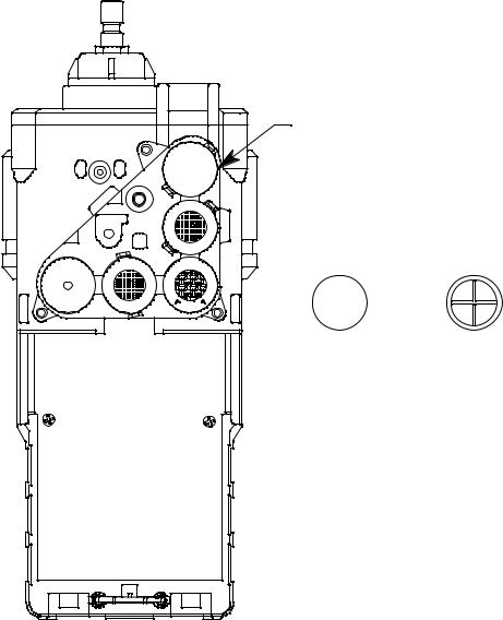
Dummy Sensors
Any unit that has less than 5 sensors will have a dummy sensor installed in one or more sensor positions. Dummy sensors are factory installed. The flat top of the dummy sensor should face up and the bottom hollow side should face down. The unit shown below is a standard 4-sensor unit for LEL/O2/
H2S/CO and has a dummy sensor installed in the %volume combustible sensor position.
Dummy Sensor
Top Flat |
Bottom |
Side |
Hollow Side |
Figure 3: Dummy Sensor
LCD
A digital LCD (liquid crystal display) is visible through a clear plastic window on the front of the case. The LCD display simultaneously shows the gas reading for all installed sensors. The display also shows information for each of the GX-2012’s program modes.
8 • Instrument Description |
GX-2012 Operator’s Manual |

Control Buttons
Five control buttons are located below the LCD. They are arranged around a central button, the POWER ENTER button. The DISPLAY (ADJ) button is on the left, the RESET SILENCE button on the right, the AIRS button on the top, and the (SHIFT)T is on the bottom.
Table 2: GX-2012 Control Button Functions
Button |
Function(s) |
|
|
|
|
POWER ENTER |
• |
turns the GX-2012 on and off. |
|
• |
used during setup and calibration. |
|
|
|
RESET SILENCE |
silences and resets audible alarm if the GX-2012 is programmed |
|
|
for latching alarms and the alarm silence option is on 1 |
|
DISPLAY (ADJ) |
• |
activates Display Mode |
|
• |
enters instructions into the GX-2012’s microprocessor |
|
|
|
AIRS |
• |
activates the demand-zero function (automatically adjusts the |
|
|
GX-2012 in fresh-air conditions) |
|
• |
scrolls through the display and settings modes |
|
|
|
(SHIFT)T |
• |
scrolls through the display and settings modes |
|
• |
enters instructions into the GX-2012’s microprocessor |
|
|
|
1 The GX-2012’s alarms are user-adjustable. See “Chapter 6: Maintenance Mode” on page 100.
Printed Circuit Boards
The GX-2012 printed circuit boards analyze, record, control, store, and display the information collected. The circuit boards are located inside the case. They are not user serviceable.
Alarm LED Arrays
Three red alarm LED (light emitting diode) arrays are visible through frosted plastic lenses in the case. One is on the top front, one on the left side, and one on the right side. The alarm LED arrays alert you to gas, low battery, and failure alarms.
Infrared Communications Port
An infrared (IR) communications port is located just below the RESET SILENCE button. The signal goes through the control button material. The data transmitted through the port is in standard IrDA protocol. A computer’s infrared port or an IrDA/USB cable connected to a computer’s USB port can be used to download data saved by the GX-2012 to a computer using the GX2012 Data Logger Management Program. See the GX-2012 Data Logger Management Program operator’s manual for data logging and downloading instructions.
GX-2012 Operator’s Manual |
Instrument Description • 9 |
Buzzer
One solid-state electronic buzzer is located inside the case. Holes on the top front of the case allow the sound to exit the case. The buzzer sounds for gas alarms, malfunctions, low battery voltage, and as an indicator during use of the GX-2012’s many display and adjustment options.
Vibrator
A vibrating motor inside the GX-2012 case vibrates for gas alarms, unit malfunctions, and as an indicator during normal use of the various modes of the GX-2012.
Batteries
Three AA-size alkaline batteries (standard) or an optional rechargeable lithium ion battery pack (3.7 VDC) power the GX-2012. Instrument run time is dependent upon battery type. At 25°C the alkaline batteries last up to 15 hours and the lithium ion battery pack lasts up to 10 hours. The battery icon in the upper right of the LCD shows remaining battery life.
When the GX-2012 detects a low battery voltage, a low battery warning is activated. When battery voltage is too low for normal operation, the GX2012 sounds a dead battery alarm.
The alkaline batteries can be replaced by removing the battery cover on the back of the case. The lithium ion pack can be replaced by removing the entire battery pack. Push the battery pack latch on the bottom of the unit toward the front of the unit to release the pack.
The lithium ion battery pack can be recharged by placing the GX-2012 in its optional battery charging station or by placing the battery pack in the charging station.
NOTE: Use of batteries or battery chargers not specified by RKI Instruments, Inc. will void the CSA classification and may void the warranty. See “Replacing or Recharging the Batteries” on page 146.
WARNING: To prevent ignition of a hazardous atmosphere, batteries must only be changed or charged in an area known to be nonhazardous.
10 • Instrument Description |
GX-2012 Operator’s Manual |
Pump
A diaphragm pump inside the GX-2012 draws the sample to the sensors. It can draw sample from as far as 50 feet from the GX-2012. The pump is not user serviceable.
CAUTION: Sample hose lengths of more than 50 feet are not recommended for the GX-2012 because of flow rate reduction.
Flow Chamber
The flow chamber is on the back of the GX-2012 and is held in place by three phillips screws. The flow chamber seals to the rubber sensor gasket which seals to the sensor faces inside the GX-2012 and routes flow from the pump to the sensors and to the exhaust port (also a part of the flow chamber).
Sensors and Filters
The sensors are located underneath the flow chamber and are only accessible if you remove the flow chamber and the sensor gasket.
An H2S removal filter disk is placed into a recess in the sensor gasket over the %LEL sensor. This filter darkens as it absorbs H2S and should be
replaced when it is a dark brown color. Check the condition of this filter quarterly.
A charcoal filter is placed into a recess in the sensor gasket over the CO sensor. The charcoal filter is black, has a woven texture, and is impregnated with an H2S absorbing material. The CO sensor will respond if exposed to
H2S and certain hydrocarbon gases. The charcoal filter disk scrubs these
gases out of the sample to avoid false CO readings. If false or elevated CO readings are noticed, especially in the presence of H2S, change the charcoal
filter.
Inlet Filter Holder
The filter holder is a clear plastic dome shaped piece on the top of the case. A male quick connect fitting is located on the inlet filter holder. This is the GX2012’s inlet fitting. A cotton dust filter is inside the filter holder. The filter holder may be removed by turning it counterclockwise and pulling it away from the case. Two flat membrane disk hydrophobic filters, a wire mesh disk, and a rubber filter retaining gasket are held in place by the filter holder and are located in the bottom of the case chamber where the filter holder is installed.
GX-2012 Operator’s Manual |
Instrument Description • 11 |
Standard Accessories
The standard accessories include the tapered rubber nozzle, belt clip, sample hose, and 10 inch probe. An optional bar hole probe is also available and is described at the end of this section.
Tapered Rubber Nozzle
A cone shaped 4 inch long rubber nozzle is included with the GX-2012 as standard. It can be installed on the inlet fitting by pushing the larger end over it. The smaller end can be inserted through a hole in a wall or some other access to an enclosed area to sample the environment.
Belt Clip
A belt clip can be mounted to the back of the case using 3 phillips head screws. The belt clip allows the GX-2012 to be securely attached to a belt.
Wrist Strap
A wrist strap is included with the GX-2012 and can be attached to the right or left wrist strap installation feature.
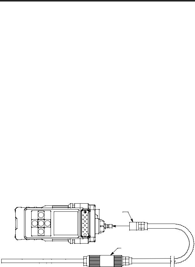
Sample Hose & 10 Inch Probe
A 10 foot sample hose and a 10 inch probe are included as standard with the GX-2012. When desired, the rubber nozzle may be removed and the sample hose and 10 inch probe may be connected to the inlet fitting. Sample hose lengths are available from 10 feet to 50 feet (see “Parts List” on page 158). The quick connect end of the sample hose connects to the inlet fitting of the GX-2012 and the probe screws onto the end of the hose with the threaded fitting.
CAUTION: Sample hose lengths of more than 50 feet are not recommended for the GX-2012 because of flow rate reduction.
Sample Hose
Probe
Figure 4: Sample Hose and Probe
12 • Standard Accessories |
GX-2012 Operator’s Manual |
Optional Accessories
Several optional accessories are available for the GX-2012. They include a rechargeable lithium ion battery pack, charging stations, various special probes, a purge tee fitting, and a dilution fitting. The most commonly used optional accessories are described below. Detailed instructions regarding the use of these and other available accessories are included in other parts of this manual. Data logging accessories are briefly described in “Data Logging” on page 56.
Rechargeable Lithium Ion Battery Pack
A rechargeable lithium ion battery pack is available for the GX-2012. A fully charged battery pack will power the GX-2012 for 10 hours. The batteries will last for a minimum of 500 charge cycles. See the “Parts List” on page 158 for ordering information.
Charging Stations
The GX-2012 lithium ion battery pack is charged with the GX-2012 charging station. Two battery charging stations are available for the GX-2012, the standard AC charging station, and a DC charging station with a vehicle plug adapter.
GX-2012 Operator’s Manual |
Optional Accessories • 13 |
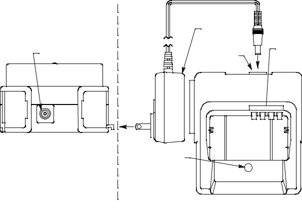
AC Powered Charging Station
The standard AC powered charging station consists of an instrument charging base and an AC adapter. The AC adapter plugs into a 115 VAC wall outlet and connects to the charging station with a jack on the end of a five foot DC output cable. The AC adapter will also work for 100 VAC or 220 VAC if an appropriate plug adapter is provided. The AC charging station is shown below in Figure 5.
|
AC Adapter |
|
|
Adapter Jack |
Adapter Jack |
Charging |
|
Contacts |
|||
|
To AC 
Outlet
Charge LED
Rear View |
|
Top View |
|
||
|
Figure 5: GX-2012 AC Powered Charging Station
14 • Optional Accessories |
GX-2012 Operator’s Manual |
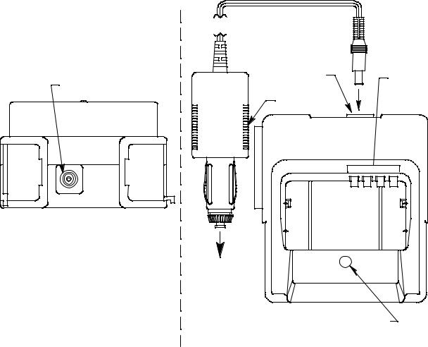
DC Powered Charging Station
An optional DC powered charging station is available with a vehicle plug 12 VDC adapter. It uses the same charging base as the AC charging station but comes with a velcro strap to secure the GX-2012 in the charging base.
Adapter Jack |
Charging |
|
Adapter Jack |
Contacts |
|
Vehicle Plug |
||
|
|
To Vehicle |
|
12 VDC |
|
Power Socket |
|
Charge LED |
Rear View |
Top View |
Figure 6: GX-2012 DC Powered Charging Station
GX-2012 Operator’s Manual |
Optional Accessories • 15 |

Optional Probes
Various optional probes designed for specific applications are available for the GX-2012. They include the following:
• 30 inch aluminum probe
Figure 7: 30 Inch Aluminum Probe
This probe is designed for applications where it is necessary to put the probe tip in areas that are out of reach with the standard probe. A small breather hole near the end of the probe tube prevents interruption of sampling and a low flow alarm if the probe tip is blocked.
• 30 inch stainless steel probe
Figure 8: 30 Inch Stainless Steel Probe
This probe is physically the same as the 30 inch aluminum probe and is intended for applications where a high level of corrosion resistance is required in the long probe tube.
• Barhole probe
End Plugged
Figure 9: Barhole Probe
An optional bar hole probe is available for the GX-2012. It is designed to be used when the GX-2012 is operated in Bar Hole Mode to check bar holes when tracking down underground gas pipe leaks (see “Chapter 4: Using the GX-2012 in Bar Hole Mode” on page 73). The bar hole probe has the same handle as the standard probe, but has a 30 inch fiberglass tube instead of the standard tube. Four holes are drilled through the 30 inch tube’s wall near the end and the end is plugged so that debris from the barhole cannot be drawn into the tube. The sample is drawn through the drilled holes in the tube wall.
16 • Optional Accessories |
GX-2012 Operator’s Manual |

• 32 inch telescoping probe with dust filter
Figure 10: 32 Inch Telescoping Probe with Dust Filter
This probe is designed for use where it is necessary to put the probe tip in areas not accessible with the 10 inch probe with dust filter and applications where the probe tube must be collapsible for storage.
• 7 foot telescoping probe with dust filter
Figure 11: 7 Foot Telescoping Probe with Dust Filter
This probe is designed for use where it is necessary to put the probe tip in areas not accessible with the 32 inch telescoping probe with dust filter and applications where the probe tube must be collapsible for storage.
• 8 meter hose with floating head
This probe is designed to be used in a tank or a well that may have water or some other liquid at the bottom. As you lower the probe down, if it hits water, it will float and continue to monitor the area.
See the “Parts List” on page 158 for probe ordering information.
GX-2012 Operator’s Manual |
Optional Accessories • 17 |

Purge Tee Fitting
The 17-4430RK-01 purge fitting is used to detect gas levels in a pressurized gas stream from a pipeline or vessel being purged. The sample port of the purge fitting is inserted into the flowing gas, and the vent port will allow any excess gas to release to the atmosphere to avoid damage to pump or sensors.
Pressurized |
Excess |
Stream |
Pressurized |
|
Sample |
Sample Port |
Vent Port |
GX-2012 Inlet
Figure 12: Purge Tee Fitting
External Dilution Fitting
An external dilution fitting is available for the GX-2012. It is a 1:1 dilution fitting and is designed to mate with the inlet fitting and accept a sample hose or probe. The fittings are made with brass and nickel plated brass and are appropriate for use with the four standard gases. The dilution fitting is normally used when it is necessary to introduce air into a sample that has no oxygen or a very low level of oxygen, such as a nitrogen purged sample. It can also be used when one of the target gas levels in the sample area will likely be present in a concentration above the detection range for that gas. Since the fittings partially consist of unplated brass, they are not appropriate for detection of elevated levels of H2S.
Figure 13: Dilution Fitting
18 • Optional Accessories |
GX-2012 Operator’s Manual |

Chapter 3: Using the GX-2012 in Normal Mode
Overview
This chapter explains how to operate the GX-2012 in Normal Mode. Normal Mode is used to perform confined space entry monitoring or general area monitoring. While in Normal Mode, Display Mode and Calibration Mode are accessible.
If a standard version of the GX-2012 is ordered, it is shipped with Bar Hole Mode disabled so that the instrument only runs in Normal Mode when turned on.
Start Up, Normal Mode
This section explains how to start up the GX-2012 in Normal Mode, get it ready for operation, and turn it off.
NOTE: The screens illustrated in this section are for a 4-gas unit that has the % LEL range for the combustible gas channel. The screens displayed by your GX-2012 may be slightly different.
Turning On the GX-2012, Normal Mode Only
The following description of the GX-2012 start up sequence assumes that the following items in Maintenance Mode are turned on: LNCH BRK, ID DISP, CL RMNDR, and BP RMNDR. If any of these items is turned off, then the corresponding screen will not appear. This description also assumes that Bar Hole Mode is not active.
1.Connect the tapered rubber nozzle or the sample hose to the GX-2012’s quick connect inlet fitting.
2.If a sample hose is used, screw the probe onto the sample hose’s threaded fitting.
3.Press and briefly hold down the POWER ENTER button. Release the button when you hear a beep.
GX-2012 Operator’s Manual |
Overview • 19 |
4. If LNCH BRK is turned on, the Resume Datalog Screen displays.
rESU
4
RESUME
•Press and release the POWER ENTER button to continue accumulating time-weighted average (TWA), PEAK readings, and time in operation from the last time the GX-2012 was used. The short-term exposure limit [STEL] reading is reset each time the GX2012 is turned on.
•Press and release the DISPLAY(ADJ) button to reset the accumulation of these measurements.
If you do not press the POWER ENTER or DISPLAY(ADJ) button within 5 seconds, the GX-2012 automatically resumes accumulating the TWA, PEAK readings, and time in operation.
5.If CL RMNDR is turned on (factory setting), the screen that appears next depends on how CL EXPRD is set in the Maintenance Mode Menu (page 131).
•If the unit is due for calibration and CL EXPRD is set to CONFIRM (factory setting), then the following screen displays.
CAL
C--LIMIT
The alarm LED’s and buzzer will pulse several times. After this, press the RESET SILENCE button until you hear a beep to continue.
20 • Start Up, Normal Mode |
GX-2012 Operator’s Manual |
•If the unit is due for calibration and CL EXPRD is set to NOT USE, then the following screen displays.
FAIL
C--LIMIT
The GX-2012 cannot be used until a calibration has been performed either by selecting AUTO CAL or ONE CAL in the Maintenance Mode menu. See “Calibrating Using Auto Calibration” on page 105 or “Calibrating Using Single Calibration” on page 108 for calibration instructions.
•If calibration is not due or CL EXPRD is set to NO EFFECT, then the following screen appears for a few seconds indicating when the next calibration is due.
2011
9
30
69d
NEXT CAL
6.If BP RMNDR is turned on (factory setting is OFF), the screen that appears next depends on how BP EXPRD is set in the Maintenance Mode Menu (page 131).
•If the unit is due for a bump test and BP EXPRD is set to CONFIRM (factory setting), then the following screen displays.
tESt
B--LIMIT
The alarm LED’s and buzzer will pulse several times. After this, press the RESET SILENCE button until you hear a beep to continue.
GX-2012 Operator’s Manual |
Start Up, Normal Mode • 21 |
•If the unit is due for a bump test and BP EXPRD is set to NOT USE, then the following screen displays.
FAIL
B--LIMIT
The GX-2012 cannot be used until a bump test has been performed by selecting BUMP in the Maintenance Mode menu. See “Performing a Bump Test” on page 111 for bump testing instructions.
•If a bump test is not due or BP EXPRD is set to NO EFFECT, then the following screen appears for a few seconds indicating when the next bump test is due.
2011
9
30
10d
NEXTBUMP
NOTE: If both CL RMNDR and BP RMNDR are turned off, a WARM UP screen will display before the warm up sequence continues.
22 • Start Up, Normal Mode |
GX-2012 Operator’s Manual |
 Loading...