

Page 1
eyeWAVE™
Wireless PIR Camera
Installation Instructions
Description
Wireless eyeWave™ is a battery powered PIR detector with an integrated camera, designed for video verification and simple installation by alarm installers. The camera captures and
transmits a sequence of images to a remote server or to mobile phones via RISCO systems, upon an intrusion event or homeowner demand
Main Features
PIR coverage 12m (40’) wide angle
VGA/VGA camera resolution with ~90° field-of-
view
Discreet IR flash allows imaging in complete
darkness, up to 10m (33’)
Two RF channels with separate antennas:
One for alarms and control; Second channel for
image transmission
Sequence of images upon event, configurable
number and interval and number of images
During disarm, events are ignored to save
battery and for privacy
On-demand images initiated from authorized
mobile phone or web browser
Option for on-arm image taking
Images stored on detector until transmission to
panel is completed
Includes 2 long-life 3V lithium batteries
Works only with video-supporting systems
PIR Model Pet Friendly Model
Installation
Step1: Preliminary Considerations
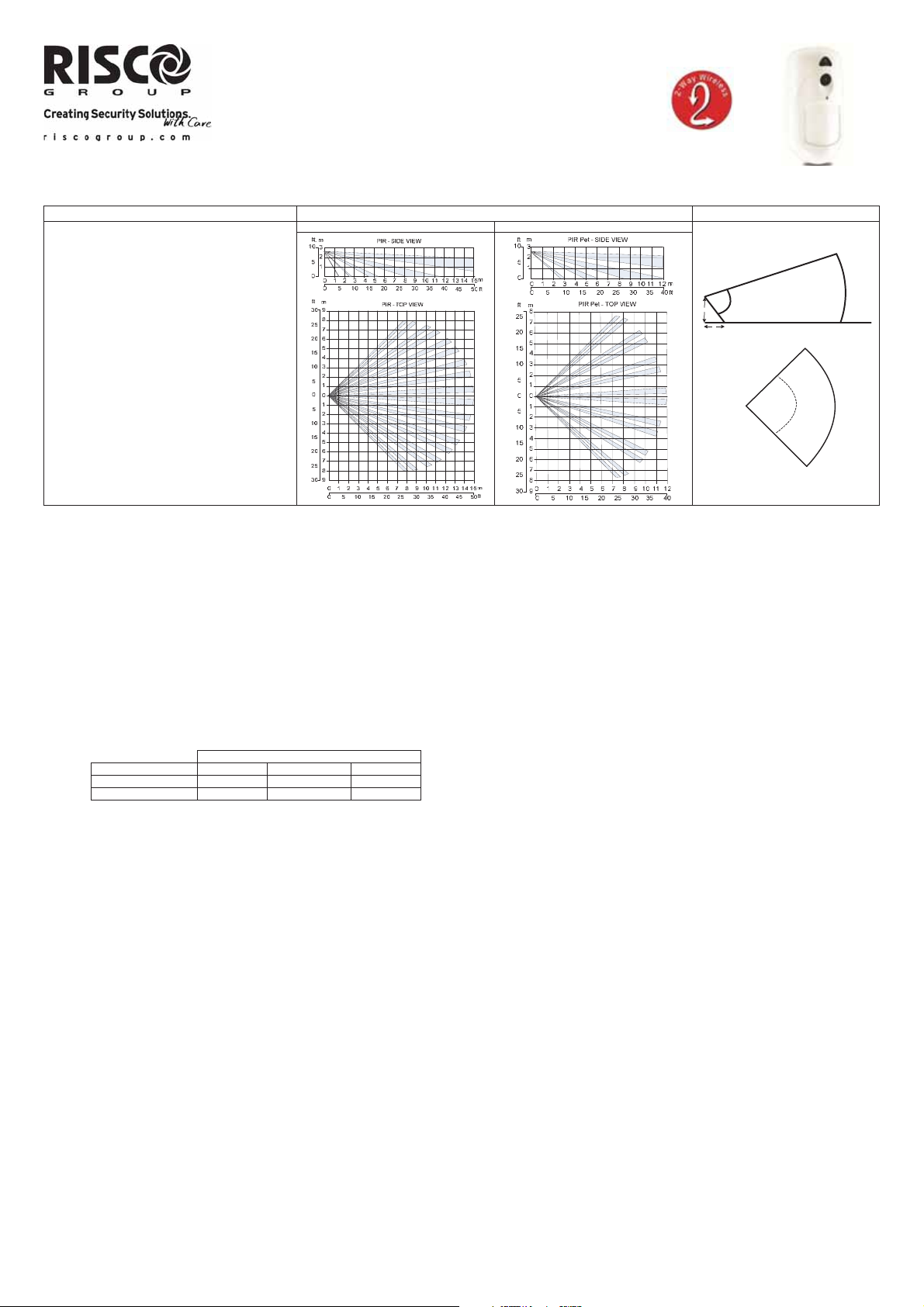
Select the mounting location for best coverage of the area that is to be protected (see Coverage Patterns).
Pay attention to the following:
Do not touch the lens with your finger as it will result in blurred image capture.
Do not mount the detector in direct sunlight or near heated sources and metal objects.
Detection sectors should be pointed towards either the wall or the floor and not towards windows and curtains.
Select mounting height according to the coverage patterns (recommended: 2.0–2.4 m in height and at least 40cm from ceiling).
Step 2: Registering the Detector into the system
The eyeWAVE must identify itself to the system receiver in a device allocation (enrollment) process, which can be performed by either RF sequence registering or entering the detector’s
11-digit serial number into the system or using RF mode (Panel Quick Key Programming Sequence:
(From the panel) 2) Radio Devices > 1) Allocation > 1) By RF or 2) By Code.
(Through Configuration Software) Click Radio Device Allocation > Enter Serial Code: [045] + [8 digits]; Indexed: Automatic or manually designated 1-32; Accessory Type: 2-Way Detector
(displayed)). Then click Allocate: RF Allocation is performed. Refer to the Sytem Installation manual for full instructions.
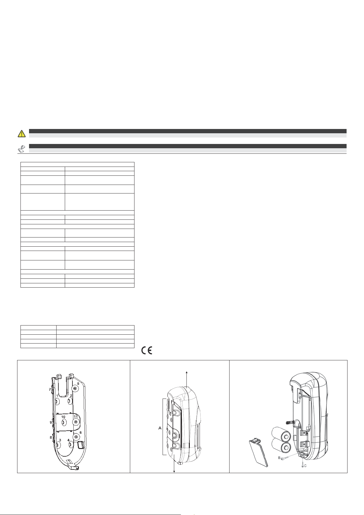
Step 3: Mounting the detector
1. Open the knockout holes of the mounting bracket, and use them as a template for mounting according to the following table (see Figure 1).
Knockout for
Bracket 7,8 1,2,3,4 5,6
Tamper 9 10 11
For Pet-Friendly Model:
In order to optimize pet immunity the following guide lines are recommended:
Mount the detector vertically at right angles to the floor.
Make sure an animal cannot get above height of 1.5m (5') by climbing on furniture, shelving or stairs.
2. Fasten the cover to the base of the detector by inserting and fastening screw (B) into the hole located inside the battery compartment. (see Figure 3)
3. Insert the batteries and close the battery compartment cover. (see Figure 3)
4. Once the bracket is installed, slide and lock the detector onto the mou nting bracket in reverse sequen ce. (see Figure 2)
5. Perform a Walk Test as described in the Walk Test section.
6. Insert and fasten screw (C) into the hole located at the bottom of the detector to lock the detector to the mounting bracket. (see Figure 3).
Step 4: Walk Test
Upon inserting the batteries, the detector goes into a Walk Test mode for 20 minutes and then automatically returns to Normal mode (To save battery power). During Walk Test Mode,
the detector will transmit after each detection. Walk test the entire field view of the detector and observe the LED for confirmation. Verify that the receiver is properly receiving the
signals
Manually initiate a walk test from the control panel:
Installation Menu: 2) Testing > 2) Zone > 3) Walk Test 1) Start Walk Test
The detector remains in walk test mode until any key on the panel is pressed. Display test results as follows:
Installation Menu: 2) Testing > 2) Zone > 3) Walk Test 2) Walk Test Results
Camera Configuration
Being bi-directional, the detectors parameters can be modified from the keypad or from the system configuration software according to your needs:
PIR Sensitivity: High/Low (Default: Low)
Supervision Time: 0-255 minutes (Default: 15 min)
LED: On/Off (Default: On)
Operation Mode.
Walk Test: The detector will transmit after each detection
Normal (Default)
For more information refer to the System Installer Guide.
Configure the camera settings through the RISCO Configuration Software (right-click on the Serial Code field in the Zones nod e screen and in the displayed pop-up click Additional..) or
through the panel quick key programming sequence as follows (default in bold):
Programming > 2) Radio Devices > 2) Modification > 1) Zone [Select (1–32)] >
1) Parameters > 6) Advanced 5) Camera Parameters:
1) Images at Alarm: 3 (1 to 7 images)
2) Image Interval: 0.5 sec (0.5, 1, 2 seco nds)
3) Pre-Alarm Image: Yes (Yes, No) (Image capture upon each arm)
4) Image Resolution: QVGA (QVGA 320X240, VGA 640X48 0)
5) Image Quality: High (High, Low)
6) Colour Image: Colour (Colour, B&W)
Mounting position
Left Flat Right
Coverage Patterns Camera FOV
70°
D
D
Side view
m
0
1
D = 2,4 m
Top view
10m
90°
1
Page 2
m
Image upon request
Taking a snapshot from the PIR Camera can be initiated by using SMS command from any remote phone
SMS Message structure: [PIN Code][V][Camera No 01-32], example: 1234V01
Images can also be taken using web/smartphone apps (on panels supporting these applications).
Event Report
Every event detected by the PIR camera is recorded into the camera’s memory. The event record consists of the date and time mark, detail description of the event inclu ding its source
and a video record.
LED Status
On: Alarm
Blinking twice: (In alarm mode) Low battery
Blinking four times: (In initial learning mode) Successful write operation
Diagnostics
You can perform diagnostic tests on your detector using the keypad or the configuration software. Diagnostics includes testing the detector battery status and the co mmunication between
the detector and the panel. For additional information refer to the System Installer Manual.
To replace the batteries:
A low battery condition is detected by a flashing LED on each transmission.
To replace the batteries:
1. Remove the detector from the mounting bracket.(Figure 2)
2. Open the battery cover.(Figure 3)
3. Replace the batteries. Pay attention to the right polarity.
4. Close the battery cover.
CAUTION:
Risk of explosion if battery is replaced by an incorrect type. Dispose of used batteries according to local regulations.
NOTE:
After replacing the batteries and closing the tamper, the detector will automatically go into in Walk Test mode for 20 minutes.
Specifications
Electrical
Battery Type: 2 x CR 123, 3V Lithium Battery
Battery Life: 2 batteries – 3 year typical lifetime
Current Consumption:
Supervision
Transmission:
RF transmitting
frequencies:
Optical
Filtering: White Light Protection
Pet friendly: Up to a 36 kg (80lb) animal (pet model)
Physical
Size: 132 x 67,5 x 56 mm
Weight: 169 grams (5.96 oz.)
Environmental
RF Immunity: According to EN50130-4
Operating Temperature:
Storage Temperature:
Camera
Type: CMOS digital image sensor
Lux: 0 Lux (total darkness)
View Angle: H 90 o V 71o
Approvals
EN50131-1,
EN50131-2-2 Grade 2,
EN50130-5 Environmental Class II,
EN50131-6: Type C
58 μA standby;
200 mA max. peak at capture with flash
0-255 minutes
868.65 MHz; 869.525 MHz for model
RWX95CM8
433.92 MHz; 916 MHz for model
RWX95CM4
(5.1 x 2.6 x 2.2 in)
-10°C a 55°C
(14°F a 140°F)
-20°C a 60°C
(-4°F a 140°F)
Ordering Information
Part Number Description
RWX95CM8000A 868.65 MHz 2-Way WL PIR & CAM Detector
RWX95CMP800A 868.65 MHz 2-Way WL PIR Pet & CAM Det.
RWX95CM4000A 433.92 MHz 2-Way WL PIR & CAM Detector
RWX95CMP400A 433.92 MHz 2-Way WL PIR Pet & CAM Det.
Figura 1: Mounting Bracket
RISCO Group Limited Warranty
RISCO Group and its subsidiaries and affiliates ("Seller") warrants its products to be free from defects in materials and workmanship
under normal use for 24 months from the date of production. Because Seller does not install or connect the product and because the
product may be used in conjunction with products not manufactured by the Seller, Seller cannot guarantee the performance of the
security system which uses this product.
Seller's obligation and liability under this warranty is expressly limited to repairing and replacing, at Seller's option, within a reasonable
time after the date of delivery, any product not meeting the specifications. Seller makes no other warranty, expressed or implied, and
makes no warranty of merchantability or of fitness for any particular purpose.
In no case shall seller be liable for any consequential or incidental damages for breach of this or any other warranty, expressed or
implied, or upon any other basis of liability whatsoever.
Seller's obligation under this warranty shall not include any transportation charges or costs of installation or any liability for direct,
indirect, or consequential damages or delay.
Seller does not represent that its product may not be compromised or circumvented; that the product will prevent any personal injury or
property loss by burglary, robbery, fire or otherwise; or that the product will in all cases provide adequate warning or protection.
Seller, in no event shall be liable for any direct or indirect damages or any other losses occurred due to any type of tampering, whether
intentional or unintentional such as masking, painting or spraying on the lenses, mirrors or any other part of the detector.
Buyer understands that a properly installed and maintained alarm may only reduce the risk of burglary, robbery or fire without warning,
but is not insurance or a guaranty that such event will not occur or that there will be no personal injury or property loss as a result
thereof.
Consequently seller shall have no liability for any personal injury, property damage or loss based on a claim that the product fails to give
warning. However, if seller is held liable, whether directly or indirectly, for any loss or damage arising under this limited warranty or
otherwise, regardless of cause or origin, seller's maximum liability shall not exceed the purchase price of the product, which shall be
complete and exclusive remedy against seller.
No employee or representative of Seller is authorized to change this warranty in any way or grant any other warranty.
WARNING: This product should be tested at least once a week.
RTTE Compliance Statement
Hereby, RISCO Ltd. declares that this equipment is in
compliance with the essential requirements and other
relevant provisions of Directive 1999/5/EC. For the CE
Declaration of Conformity please refer to our website:
www.riscogroup.com
Figura 2: Remove detector from
Mounting Bracket
Contacting RISCO Group
RISCO Group is committed to customer service and product support. You
can contact us through our website www.riscogroup.com or as follows:
United Kingdom
Tel: +44-(0)-161-655-5500
E-mail: support-uk@riscogroup.com
Italy
Tel: +39-02-66590054
E-mail: support-it@riscogroup.com
Spain
Tel: +34-91-490-2133
E-mail: support-es@riscogroup.com
France
Tel: +33-164-73-28-50
E-mail: support-fr@riscogroup.com
Belgium (Benelux)
Tel: +32-2522-7622
E-mail: support-be@riscogroup.com
China (Shanghai)
Tel: +86-21-52-39-0066
E-mail: support-cn@riscogroup.com
China (Shenzhen)
Tel: +86-755-82789285
E-mail: support-cn@riscogroup.com
Polonia
Tel: +48-22-500-28-40
E-mail: support-pl@riscogroup.com
Brazil
Tel: +55-11-3661-8767
E-mail: support-br@riscogroup.com
Israel
Tel: +972-3-963-7777
E-mail: support@riscogroup.com
USA
Tel: +1-631-719-4400
E-mail: support-usa
@riscogroup.co
Figura 3: Insert batteries
Specifications are subject to change without prior notice. Should any questions arise please contact your supplier.
© RISCO Group 07/13 5IN1639 D
2
 Loading...