


User Manual

INTRODUCTION
Thank you for choosing our product.
The accessories described in this manual are of the highest quality, carefully designed and built in order to ensure excellent performance.
This manual contains detailed instructions on how to install and use the product.
It should be kept with care near the MultiCOM 401, so that it can be consulted for information on how to use and make the most of your device. IT SHOULD BE READ BEFORE YOU START WORKING ON THE DEVICE.
SAFETY
This part of the manual contains SAFETY precautions that must be followed scrupulously.
The device has been designed for professional use and is therefore not suitable for use in the home.
The device has been designed to operate only in closed environments. It should be installed in rooms where there are no inflammable liquids, gas or other harmful substances.
Take care that no water or liquids and/or foreign bodies fall into the device.
In the event of a fault and/or impaired operation of the device, do not attempt to repair it but contact the authorized service centre.
The device must be used exclusively for the purpose for which it was designed. Any other use is to be considered improper and as such dangerous. The manufacturer declines all responsibility for damage caused by improper, wrong and unreasonable use.
©No part of this manual may be reproduced without the prior written permission of the manufacturer.
The manufacturer reserves the right to modify the product described in this manual at any time and without notice.
3

SUMMARY
PRESENTATION___________________________________________________5
DESCRIPTION __________________________________________________________ 5
OPENING THE PACKAGING AND CHECKING THE CONTENTS __________________________ 6
INSTALLATION AND CONFIGURATION________________________________7
ADDRESS CONFIGURATION_________________________________________________ 7
BUS TERMINATION AND BIASING _____________________________________________ 8
JUMPER SETTINGS_______________________________________________________ 9
CONNECTION TO THE UPS_________________________________________________ 9
PROFIDRIVE MODE _______________________________________________10
CYCLIC COMMUNICATION (PROCESS DATA) ____________________________________ 10
PKW-PART___________________________________________________________ 11
PZD-PART ___________________________________________________________ 14
USER DEFINED PZD SLOTS _______________________________________________ 14
PERMANENT PZD CONFIGURATION _________________________________________ 15
LIST OF PARAMETERS ____________________________________________16
UPS PARAMETERS _____________________________________________________ 16
GATEWAY INTERNAL PARAMETERS__________________________________________ 19
PROFIDRIVE STANDARD PARAMETERS _______________________________________ 19
CONNECTORS PINOUT____________________________________________21
DIAGNOSTIC LED ________________________________________________22
4
PRESENTATION
DESCRIPTION
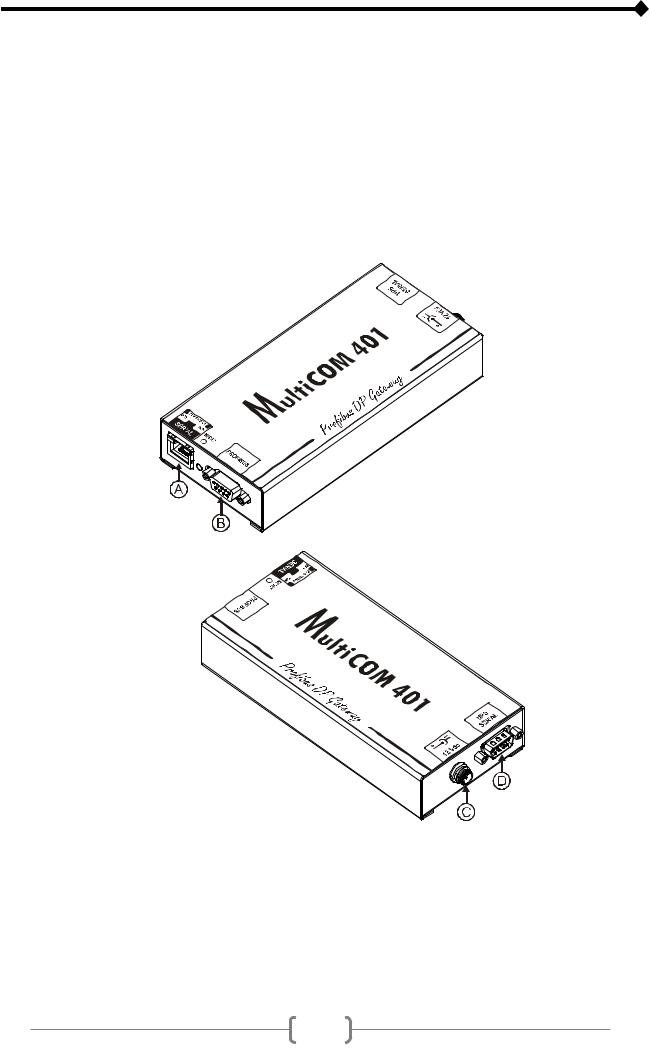
MultiCOM 401 allows you to connect the UPS to a Profibus DP network. The device enables to integrate, in industrial enviroment, the management and monitoring of the UPS into a control system based on one of the most popular field bus designed especially for communication between automation control systems and distributed I/O. Baud rates from 9.6 kbit/s up to 12 Mbit/s are supported and automatically detected.
The device also offers an RS-232 serial line through which the UPS can be monitored using the GPSER protocol (PRTK code: GPSER11201...).
•A: RS-232 communication port
•B: PROFIBUS connector
•C: power supply connector
•D: connector for connection to the UPS
5
OPENING THE PACKAGING AND CHECKING THE CONTENTS
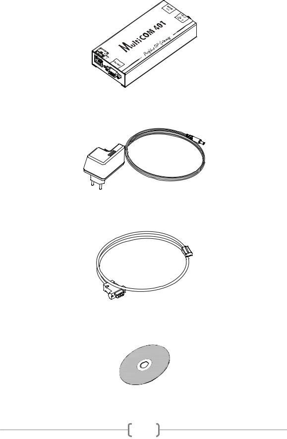
After opening the packaging, first check the contents.
The packaging should contain:
MultiCOM 401
12Vdc 0.5A external power supply unit
DB9-RJ45 serial cable
CD-Rom (User manual and GSD file)
6

INSTALLATION AND CONFIGURATION
In order to access the DIP-switches and the jumpers, disconnect the device from the power supply, remove the 4 screws on the base and then remove the cover
ADDRESS CONFIGURATION
The Profibus address must be configured using the SW1 and SW2 rotary switch (shown in the figure). Allowable addresses are 1÷99.
7
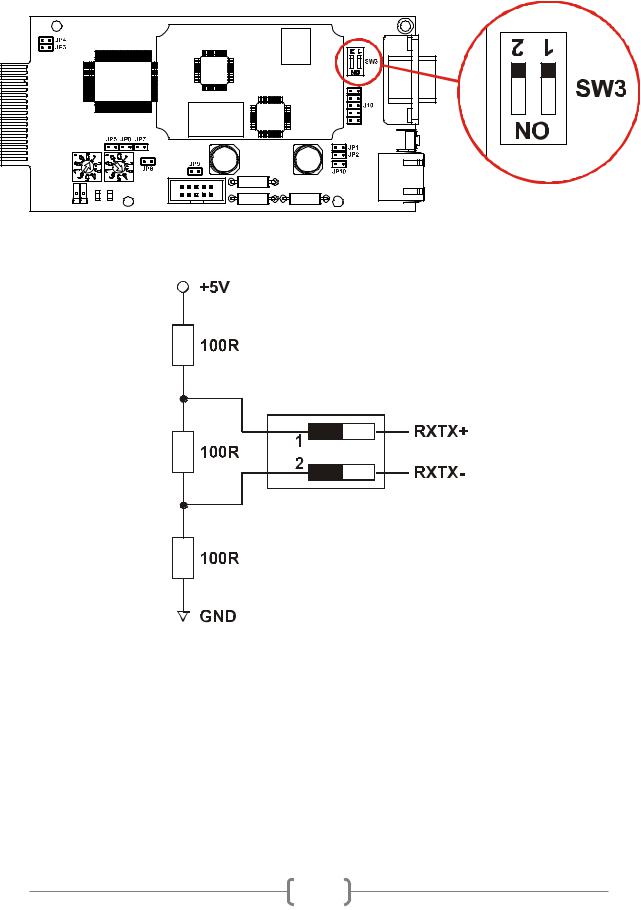
BUS TERMINATION AND BIASING
MultiCOM 401 is supplied with the bus termination and biasing resistors already mounted internally (R=100Ω). Dip-switch SW3 must be closed in order to insert these resistors (see figure).
8
 Loading...