

RIDGID LR-60B, LS-60B Instructions Manual
Test Equipment Depot - 800.517.8431 - 99 Washington Street Melrose, MA 02176 - TestEquipmentDepot.com
LR-60B/LS-60 Latching Crimp Heads Instructions
WARNING
Read and understand
these instructions, the
electrical tool instructions, the instructions
for the dies to be used,
connector to be crimped and the warnings and instructions for all
equipment and material being used before operating this tool to
reduce the risk of serious personal injury.
the instructions for the
SAVE THESE INSTRUCTIONS!
• Keep your fingers and hands away from the crimp head during
the crimping cycle. Your fingers or hands can be crushed, fractured
or amputated if they are caught between the dies or the components
and any other object.
• Do not use on energized electrical lines to reduce the risk of elec-
trical shock, severe injury and death. Tool is not insulated Use
appropriate work procedures and personal protective equipment when
working near energized electrical lines.
• Large forces are generated during product use that can break or
throw parts and cause injury. Stand clear during use and wear appropriate protective equipment, including eye protection.
• Never repair a damaged head.A head that has been welded, ground,
drilled or modified in any manner can break during use. Never replace
individual components. Discard damaged heads to reduce the risk of
injury.
• Use proper tool, die, connector and cable combination. Improper
combinations can result in an incomplete or improper crimp which increases the risk of fire, severe injury or death.
NOTICE
Sel
ection of appropriate materials and joining methods is the
responsibility of the system designer and/or installer. Before any installation is attempted, careful evaluation of the specific re quire ments should be
completed. Consult connector manufacturer for selection information.
Description
RIDGID®LR-60B/LS-60B Latching Crimp Head Tools are designed to
crimp electrical compression connectors to their respective wire when
used with appropriate dies.
The tool is available either as an interchangeable head (For RIDGID
RE 6/RE 60 or Ilsco Electrical Tool) or as part of a dedicated tool (RIDGID
RE-600 series tools).
Round
Dies
Latch
Square
Dies
Max. Cable Size...................300 mm
2
185 mm
600 MCM 350 MCM
Go to RIDGID.com/CrimpDies for the RIDGID Crimp Die/Electrical
Connector Compatibility Charts.
Tool Input Force ...................60 kN (6-ton) (13,500 lbs.)
QCS Coupling Type .............6T QCS and 60kN QCS
Interchangeable Head
Weight..................................3.4 lbs. (1.6 kg) 3.4 lbs. (1.6 kg)
WARNING
Do not use LR-60B/LS-60B Crimp Heads with RIDGID
RE 53 Electrical Crimp Tools. This may cause incomplete crimps.
Inspection/Maintenance
Inspect the Latching Crimp Head before each use for issues that could
affect safe use.
1. Remove battery from electrical tool.
2. Clean any oil, grease or dirt from the tool and head, including handles and controls. This aids inspection and helps prevent the machine from slipping from your grip.
3. Inspect the head for:
• Proper assembly and completeness.
• Wear, corrosion or other damage. Make sure that the latch works
properly and securely closes.
• Presence and readability of head markings.
• See electrical tool manual for inspection and maintenance of the
QCS coupling
If any issues are found, do not use the tool until corrected.
4. Inspect the electrical tool and any other equipment being used as
directed in their instructions. Confirm that the crimp dies are a clean,
undamaged matched set.
5. Lubricate the head pivot points with a light weight general purpose
lubricating oil. Wipe off any excess oil.
Set Up/Operation
1. Prepare the connection to be crimped per the connector manufacturer’s instructions.
2. Choose the appropriate crimp dies and equipment for the application per their specifications. Make sure all equipment is inspected
and set up per its instructions.
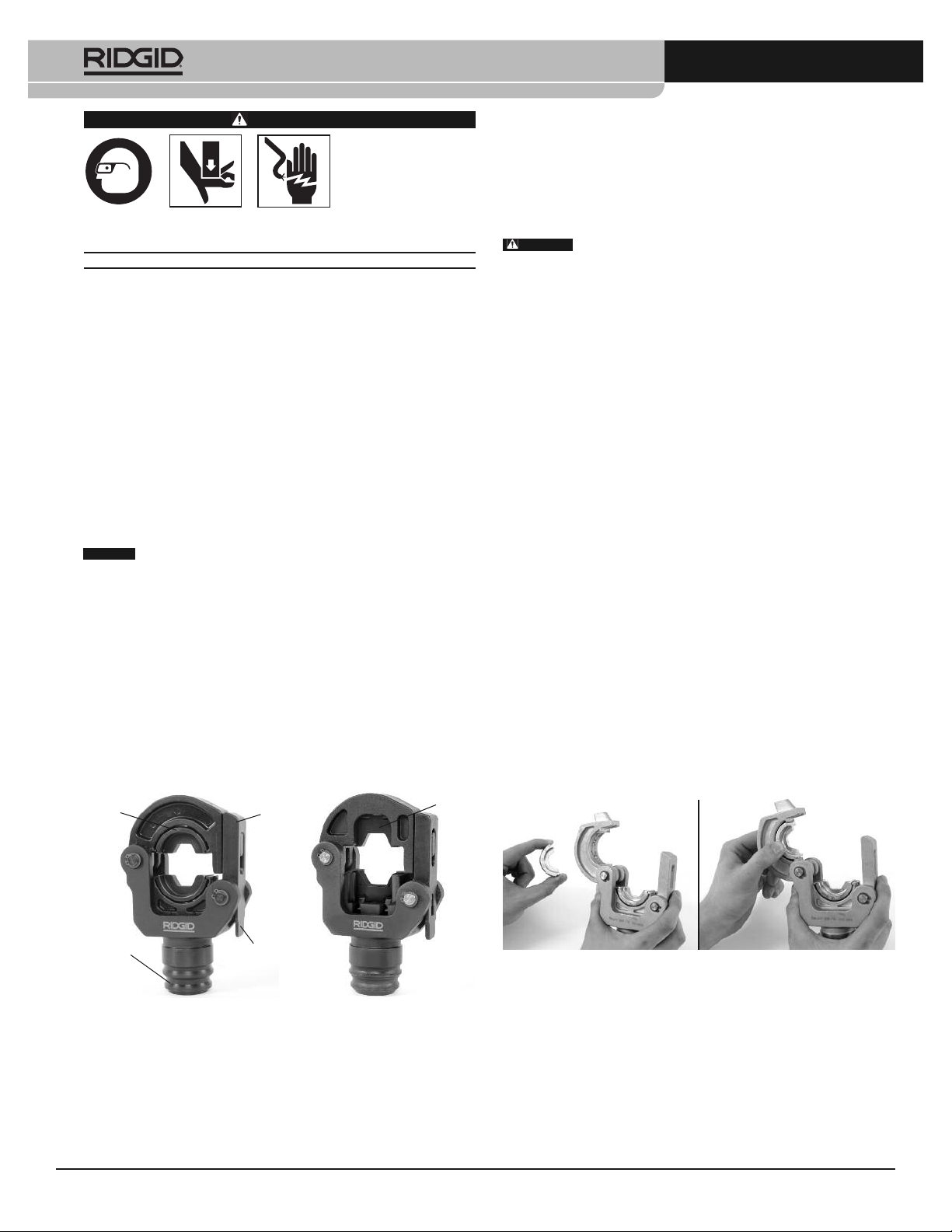
3. Remove battery from electrical tool. Open the Latching Crimp Head
by pressing the latch release. Insert matching dies into the head.
Dies should fit snugly and securely, and the crimping profiles should
®
®
align. Do not force dies into head. If there are any issues with die fit,
do not use the tool. Do not operate tool without dies installed.
Do not use with 12 ton or 130 kN dies. This could cause improper
crimp connections.
2
QCS
Coupling
Latch
Release
Figure 2 – Installing Dies in Crimp Head
4. Changing Heads with QCS Coupling – See electrical tool manual.
Figure 1 – Round Crimp Head Square Crimp Head
(Interchangeable versions)
Specification
Dies Used ............................Commercially Commercially
RIDGID Die Series...............RDD-60, RDK-60 SDD-60
Printed 2/17
EC42593 REV. D
LR-60B LS-60B
Available Round Available Square
60 kN & 6 Ton 60 kN
Conforming to DIN
48083 Type 6M
©2015, 2017 RIDGID, Inc.
The Emerson logo and RIDGID logo are registered trademarks of Emerson Electric Co. or RIDGID, Inc. in the U.S. and other countries.
All other trademarks belong to their respective holders.
5. With dry hands install the tool battery.
6. If needed, open the head by pressing the latch release and close
the head around the connector to be crimped. Make sure that the
latch is fully closed – do not operate the tool with the latch open or
partially open.
7. Follow all compression connector manufacturers’ instructions for
crimp location. Some wire sizes may require more than one crimp
per connection.
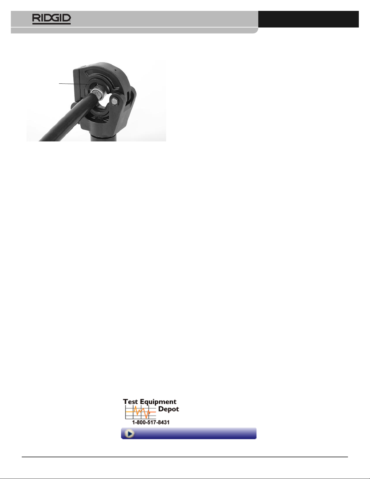
Center the connector squarely against the crimp profile in the stationary die. Improper placement can make an incorrect crimp or
damage the equipment.
999-999-472.09
LR-60B/LS-60B Latching Crimp Heads Instructions
If making a single crimp, line up the dies within the lines on the connector. If making multiple crimps on the connector, ensure there is
enough room to evenly space crimps between lug lines.
Stationary Die
Figure 3 – Aligning the Connector in the Dies
8. With hands clear of the head and other moving parts, operate the
Electrical Tool as per its instructions. After a complete cycle the ram
will retract and the tool will stop. If the ram does not retract, the crimp
is not complete and must be repeated.
9. If the ram does not fully retract, press the electrical tool pressure release button. If needed, move the head and repeat the procedure for
multiple crimps.
10. Remove the crimped connection from the head.
11. Inspect and test the connection in accordance with fitting supplier instructions, normal practice and applicable codes.
99 Washington Street
Melrose, MA 02176
Phone 781-665-1400
Toll Free 1-800-517-8431
Visit us at www.TestEquipmentDepot.com
 Loading...