

Ricoh SR3020, SR3110, SR3030, SR3120 Field Service Manual

Booklet Finisher SR3020/SR3110
/Finisher SR3030/SR3120
Machine Code: B804/D637/B805/D636
Field Service Manual
September, 2011
Subject to change


Safety and Symbols
Replacement Procedure Safety
• Turn off the main power switch and unplug the machine before beginning any of the replacement
procedures in this manual.
Symbols Used in this Manual
This manual uses the following symbols.
*: See or Refer to
: Screws
: Connector
: Clip ring
: E-ring
1

TABLE OF CONTENTS
Safety and Symbols............................................................................................................................................1
Replacement Procedure Safety.....................................................................................................................1
Symbols Used in this Manual........................................................................................................................1
1. Replacement and Adjustment
Covers..................................................................................................................................................................5
Exterior Covers...............................................................................................................................................5
Upper Tray, End Fence..................................................................................................................................5
Main Unit.............................................................................................................................................................7
Upper Tray Limit Sensor, Limit Switch...........................................................................................................7
Positioning Roller............................................................................................................................................8
Proof Tray Exit Sensor....................................................................................................................................9
Upper Tray Height Sensors 1, 2...................................................................................................................9
Exit Guide Plate, Upper Tray Exit Sensor...................................................................................................10
Proof Tray Full Sensor..................................................................................................................................11
Finisher Entrance Sensor.............................................................................................................................12
Pre-Stack Tray Exit Sensor...........................................................................................................................12
Stapler Unit.......................................................................................................................................................14
Corner Stapler..............................................................................................................................................14
Positioning Roller..........................................................................................................................................15
Fold Unit............................................................................................................................................................16
Fold Unit........................................................................................................................................................16
Fold Unit Entrance Sensor...........................................................................................................................18
Fold Unit Exit Sensor....................................................................................................................................19
Stack Present Sensor....................................................................................................................................20
Folding Horizontal Skew Adjustment (For B804 only).............................................................................21
Fold Vertical Skew Adjustment (For B804 only).......................................................................................23
Booklet Stapler Unit.........................................................................................................................................25
Booklet Stapler.............................................................................................................................................25
Booklet Stapler Motor.................................................................................................................................25
2. Detailed Section Descriptions
Component Layout...........................................................................................................................................29
General Layout............................................................................................................................................29
Electrical Components.................................................................................................................................31
2

Summary of Electrical Components............................................................................................................35
Drive Layout..................................................................................................................................................44
Junction Gates..................................................................................................................................................45
Proof Mode..................................................................................................................................................45
Shift Mode....................................................................................................................................................46
Staple Mode................................................................................................................................................46
Pre-Stacking .....................................................................................................................................................47
Tray Movement Mechanism............................................................................................................................49
Upper Tray...................................................................................................................................................49
Lower Tray (B804 Only).............................................................................................................................51
Corner Stapling................................................................................................................................................54
Stacking and Jogging..................................................................................................................................54
Stapler Movement.......................................................................................................................................55
Corner Stapling............................................................................................................................................57
Booklet Stapling (B804 Only)........................................................................................................................58
Booklet Pressure Mechanism......................................................................................................................58
Booklet Stapling and Folding ....................................................................................................................59
Booklet Stapling and Folding Mechanisms...............................................................................................65
Upper Tray Output...........................................................................................................................................68
Feed Out.......................................................................................................................................................68
Feed Out Stacking.......................................................................................................................................69
Punch Unit B702 (For B804/B805)..............................................................................................................70
Overview of Operation...............................................................................................................................70
Punch Mechanisms......................................................................................................................................73
Punch Hopper Mechanism..........................................................................................................................76
Finisher Jam Detection.....................................................................................................................................78
3

4
1. Replacement and Adjustment
Covers
Exterior Covers
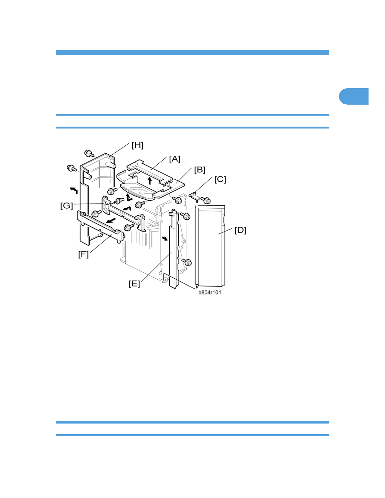
1. Open the front door [D].
2. Small upper cover [A] ( x1)
3. Upper cover [B] ( x2)
4. Front door bracket [C] ( x1)
5. Front door [D]
6. Front left side cover [E] ( x2)
7. Cover [F]
8. Paper exit cover [G] ( x2)
9. Rear cover [H] ( x2)
Upper Tray, End Fence
1. Remove the rear cover. (* "Exterior Covers")
5
1
1. Support the tray [A] with your right hand.
2. Pull gear [B] toward you ¬ to release.
3. Slowly lower the tray until it stops.
4. Front side cover [C] ( x1)
5. Rear side cover [D] ( x1)
6. Upper tray [E] ( x1)
7. Tray bracket [F] ( x4, x1 shoulder screw ¬)
8. End Fence [G]( x3)
1. Replacement and Adjustment
6
1
Main Unit
Upper Tray Limit Sensor, Limit Switch
1. Front door, front left side cover, rear cover, upper cover (* "Exterior Cover")
2. End fence (* "Upper Tray, End Fence")
3. Upper tray exit mechanism [A] ( x4, x3)
4. Upper tray limit sensor [B] ( x1, x1)
5. Upper tray limit switch [C] ( x2)
Main Unit
7
1
Positioning Roller
1. Open the front door [A].
2. Pull out the stapling unit [B].
3. Positioning roller [C] ( x1, timing belt x1)
1. Replacement and Adjustment
8
1
Proof Tray Exit Sensor
1. Small upper cover (* "Exterior Cover")
2. Proof tray exit sensor bracket [A] ( x1)
3. Proof tray exit sensor [B] ( x1)
Upper Tray Height Sensors 1, 2
1. Small upper cover, upper cover (* "Exterior Cover")
2. Upper tray paper height sensor bracket [A] ( x1)
3. Upper tray paper height sensor [B] – staple mode (S08) ( x1)
Main Unit
9
1
4. Upper tray paper height sensor [C] – non-staple mode (S09) ( x1)
Exit Guide Plate, Upper Tray Exit Sensor
1. Rear cover, Upper covers, Front door, Cover, Paper exit cover (* "Exterior Cover")
2. Inner cover [A] ( x2)
3. Exit guide plate [B] ( x1, Link and spring, x1, x1)
4. Upper tray exit sensor [C] (S6) ( x1)
1. Replacement and Adjustment
10
1
Proof Tray Full Sensor
1. Exit guide plate. (* "Exit Guide Plate, Upper Tray Exit Sensor")
2. Guide plate [A] (hook x 2)
3. Sensor bracket [B] ( x1)
4. Proof tray full sensor [C] (S11) ( x1)
Main Unit
11
1
Finisher Entrance Sensor
1. Disconnect the finisher if it is connected to the copier.
2. Sensor bracket [A] ( x1)
3. Finisher entrance sensor [B] (S1) ( x1)
Pre-Stack Tray Exit Sensor
1. Disconnect the finisher if it is connected to the copier.
1. Replacement and Adjustment
12
1

2. Sensor bracket [A]
3. Pre-stack tray exit sensor [B] (S2)
Main Unit
13
1
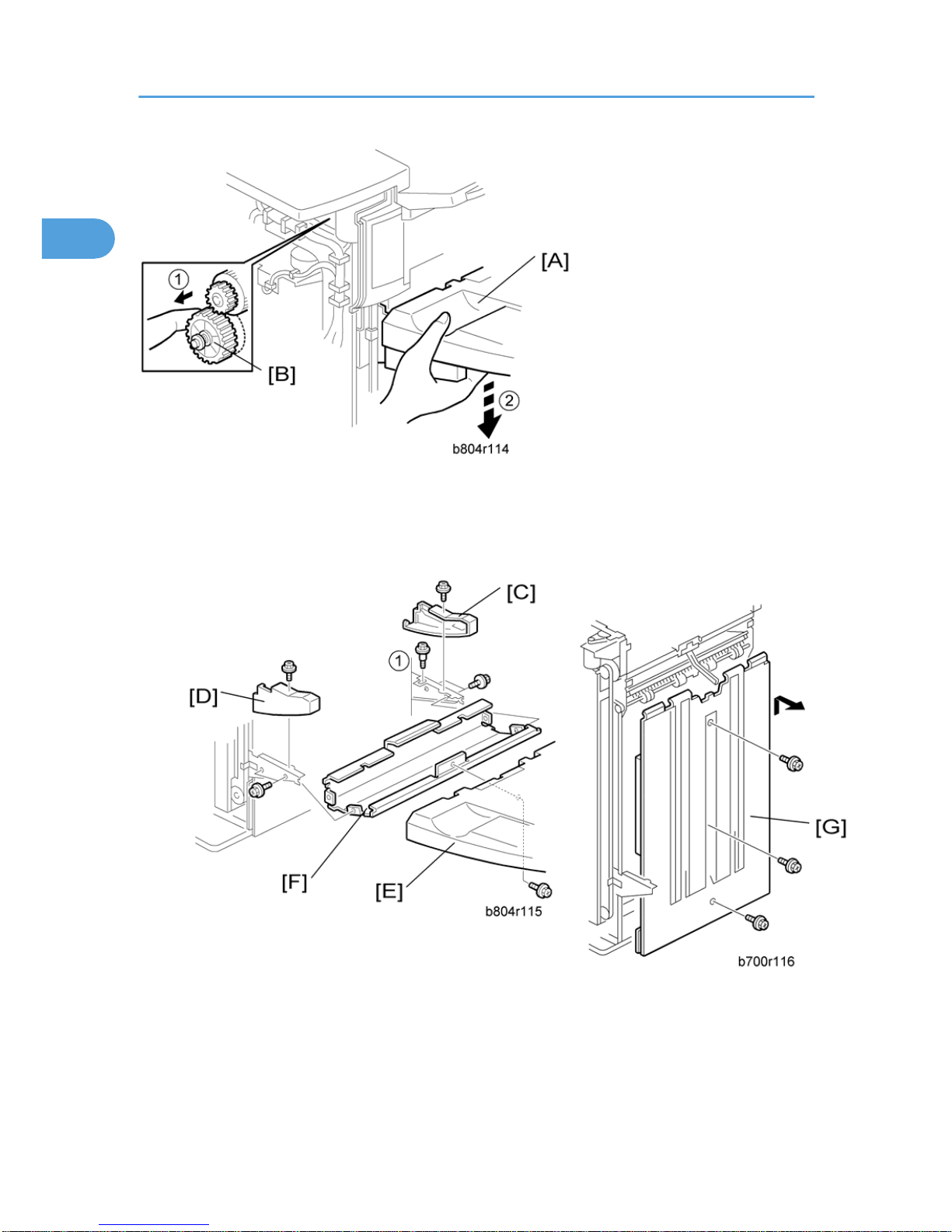
Stapler Unit
Corner Stapler
1. Open the front door.
2. Pull out the stapler unit.
3. Inner cover [A] ( x3)
4. Stapler unit holder [B] ( x1)
5. Corner stapler [C] (M20) ( x1)
1. Replacement and Adjustment
14
1
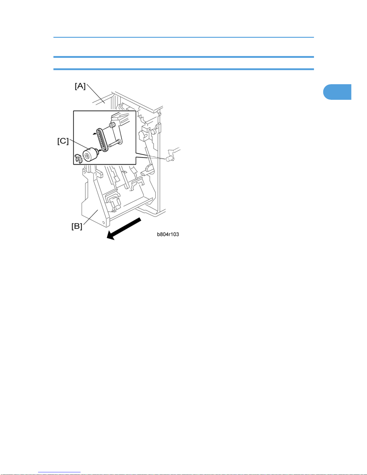
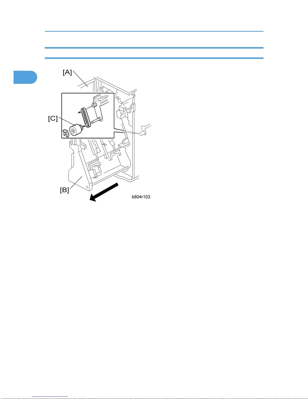
Positioning Roller
1. Open the front door [A].
2. Pull out the stapling unit [B].
3. Positioning roller [C] ( x1, timing belt x1)
Stapler Unit
15
1
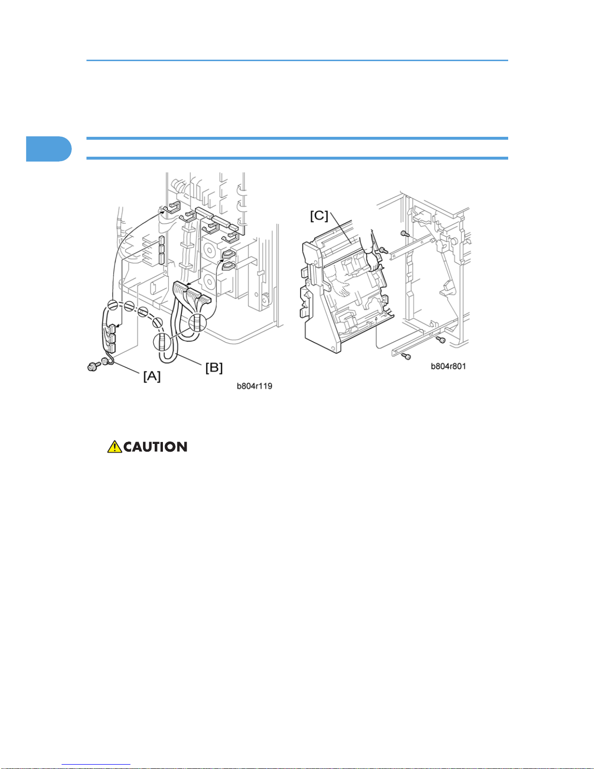
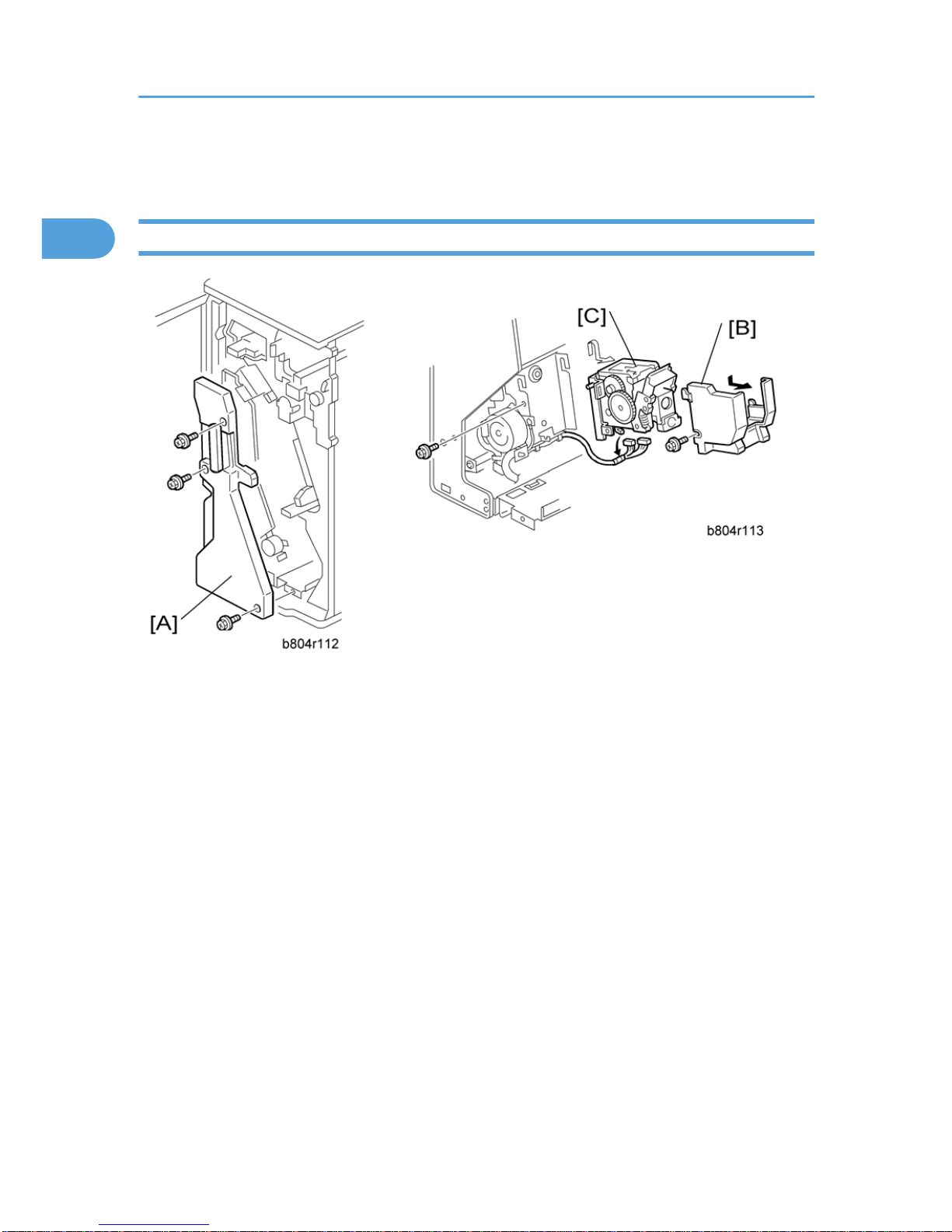
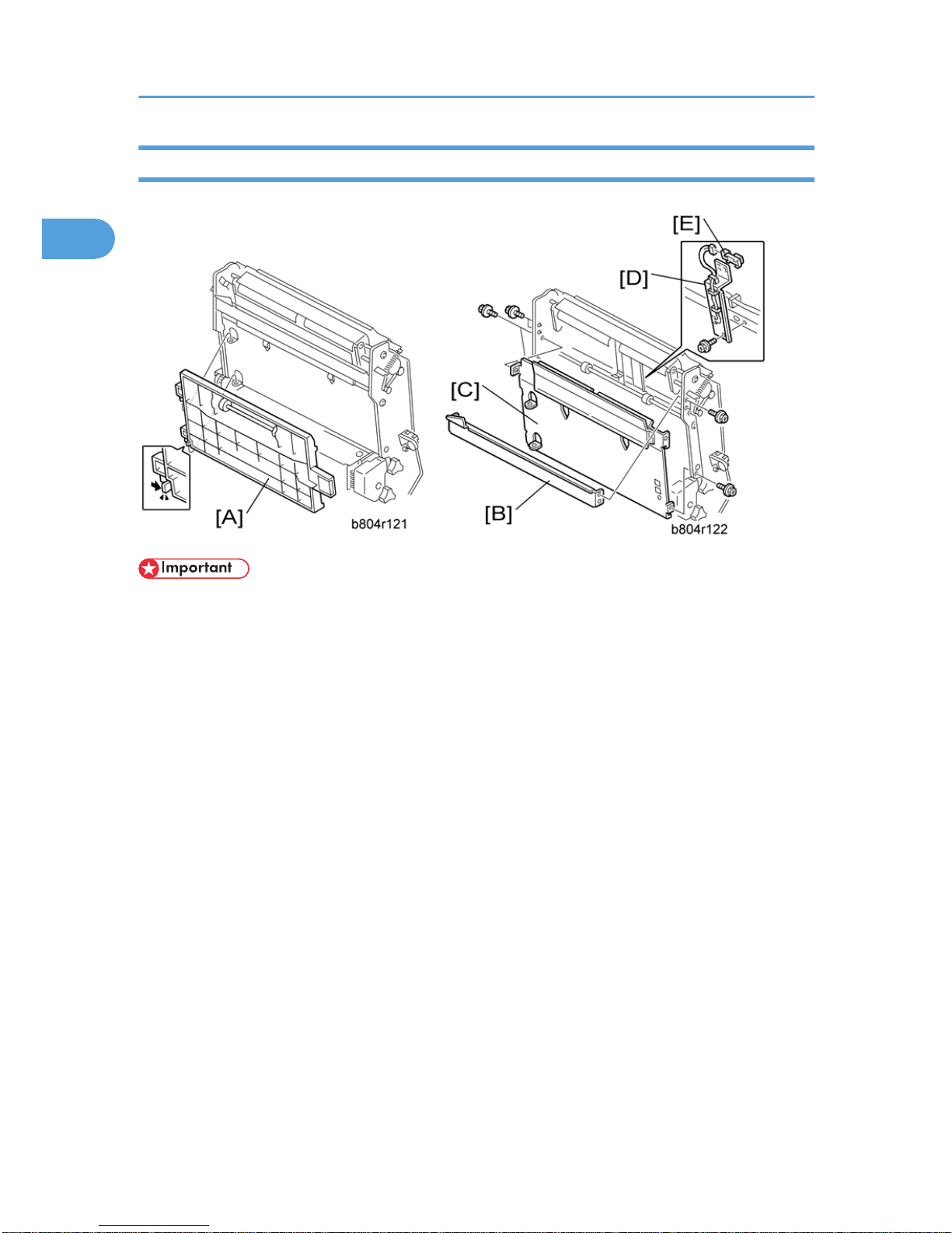
Fold Unit
Fold Unit
1. Remove the back cover (* "Exterior Covers").
2. Open the front door.
• The stapler unit is heavy.
3. Ground cable [A] ( x1)
4. Harness [B] ( x6, x6)
5. Stapler unit [C] ( x4)
1. Replacement and Adjustment
16
1
• Support the fold unit with your hand to prevent it from falling.
• The fold unit is heavy.
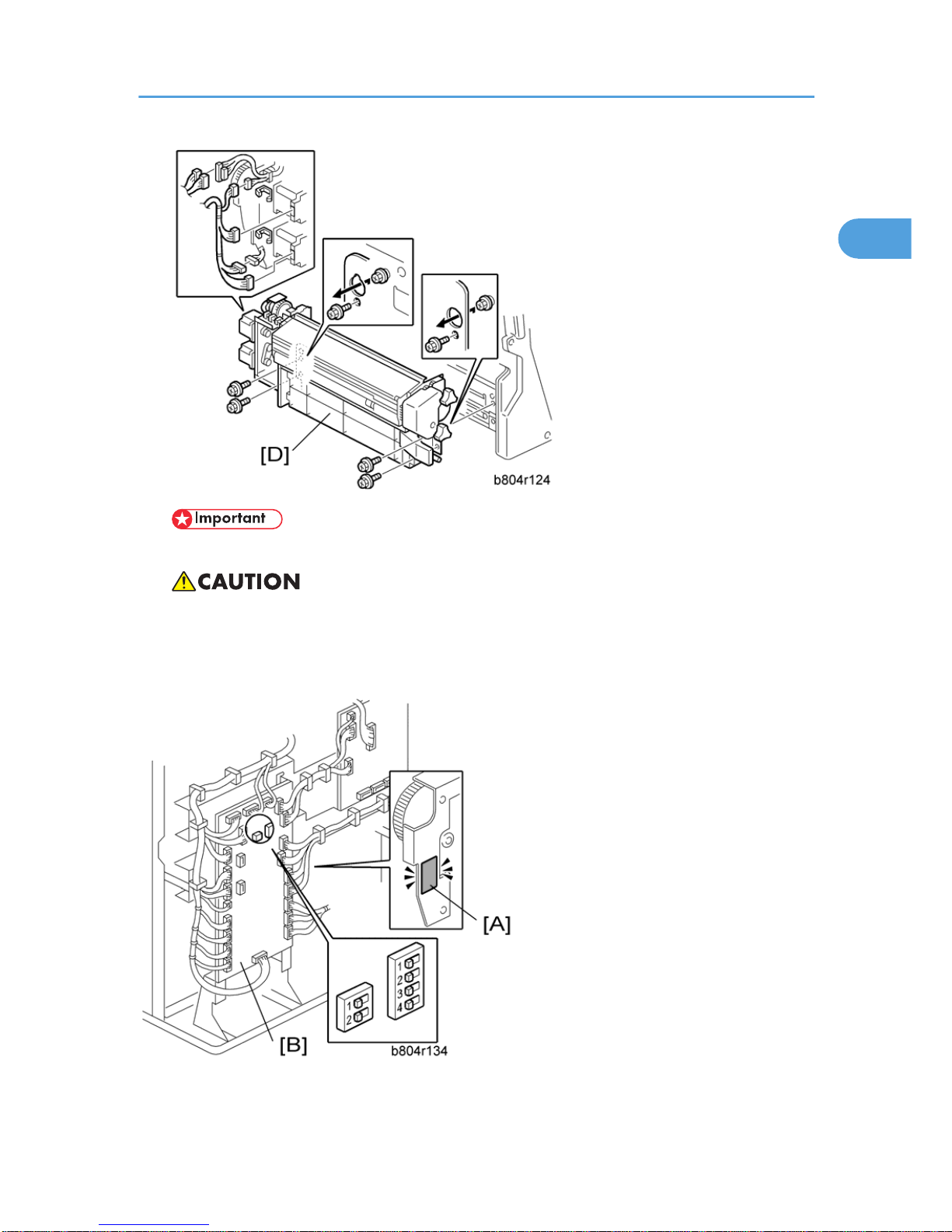
6. Folding unit [D] ( x4, x2, x6)
If you have replaced the folding unit:
1. Read the DIP SW settings on the decal [A] attached to the back of the new folding unit.
Fold Unit
17
1

2. Check the DIP SW settings on the main board [B] of the finisher.
3. If these settings are different, change these settings to match the settings printed on the decal attached
to the folding unit.
• Set DIP switches 1 to 4 (the switch set on the right). Do not touch the other DIP switches.
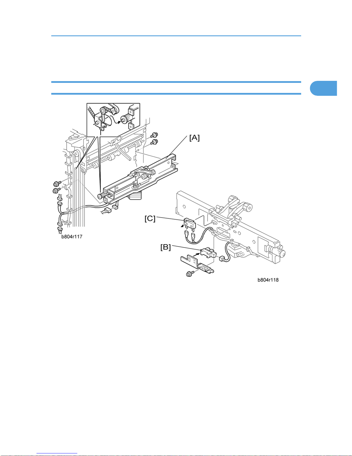
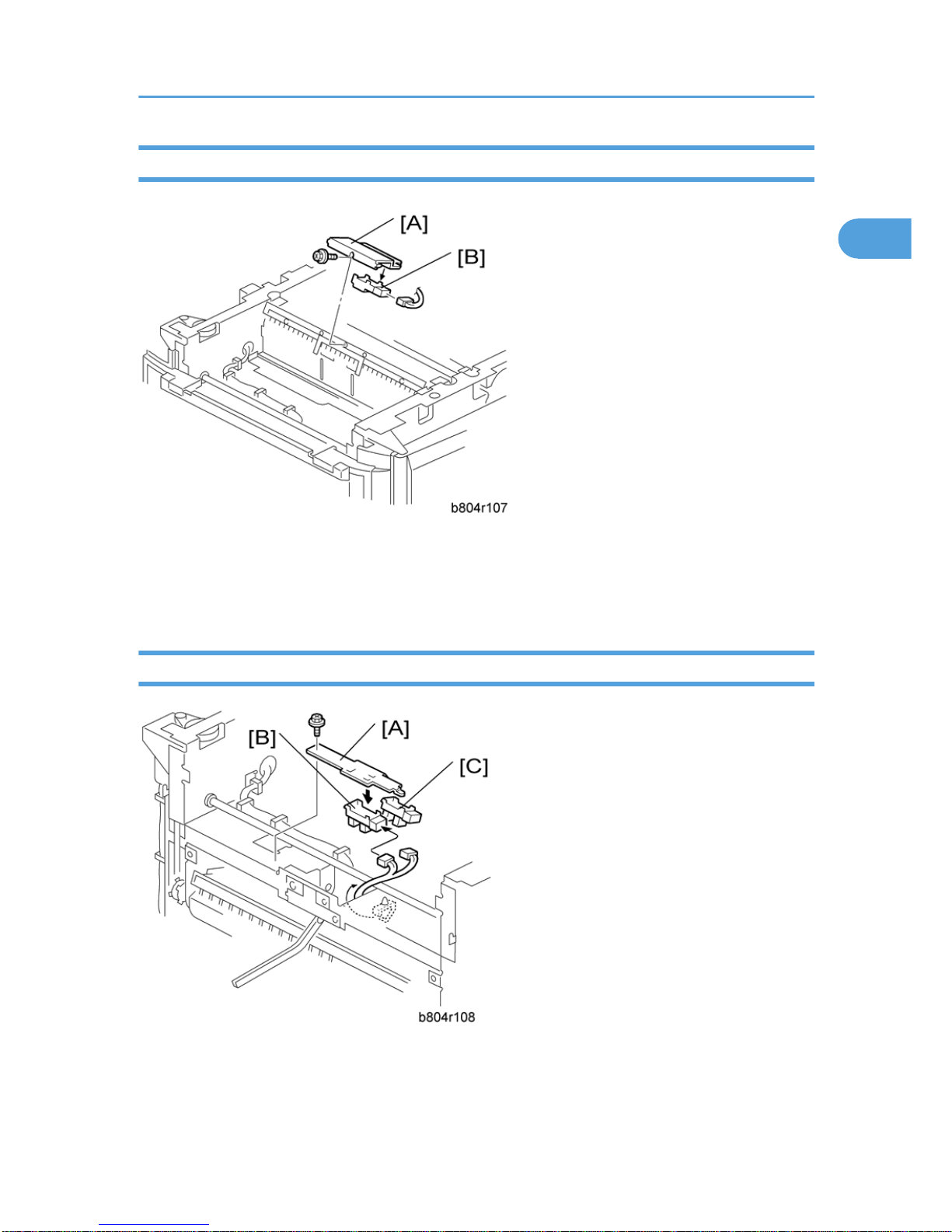
Fold Unit Entrance Sensor
1. Pull out the stapler unit (* "Positioning Roller").
2. Fold unit entrance sensor bracket [A] ( x2)
3. Fold unit entrance sensor [B] (S26) ( x1, x1)
1. Replacement and Adjustment
18
1

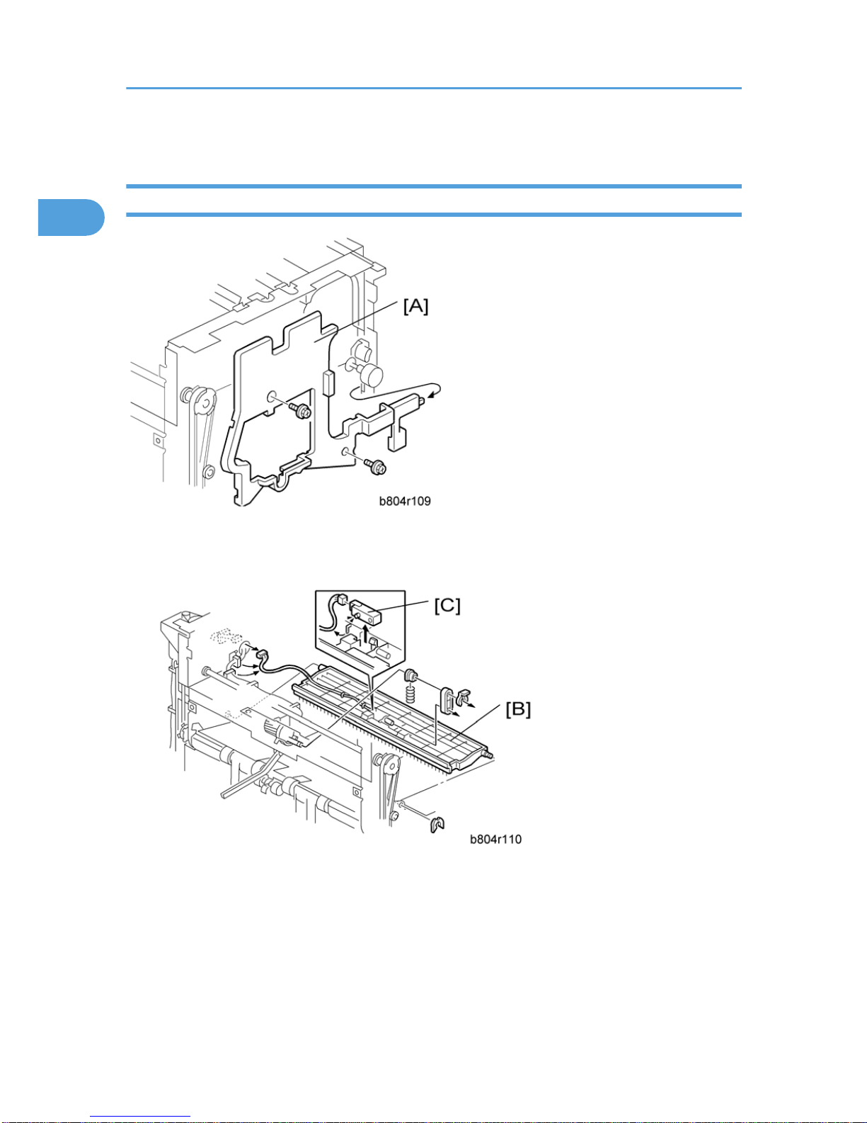
Fold Unit Exit Sensor
1. Open the front door.
2. Pull out the stapler unit (* "Positioning Roller").
3. Fold unit vertical guide plate [A]
4. Fold unit inner cover [B] ( x2, Spring pin x1)
5. Fold unit upper cover [C] ( x1)
6. Paper clamp mechanism [D] ( x4)
7. Fold unit exit sensor bracket [E] ( x1)
8. Fold unit exit sensor [F] (S31) ( x1)
Fold Unit
19
1
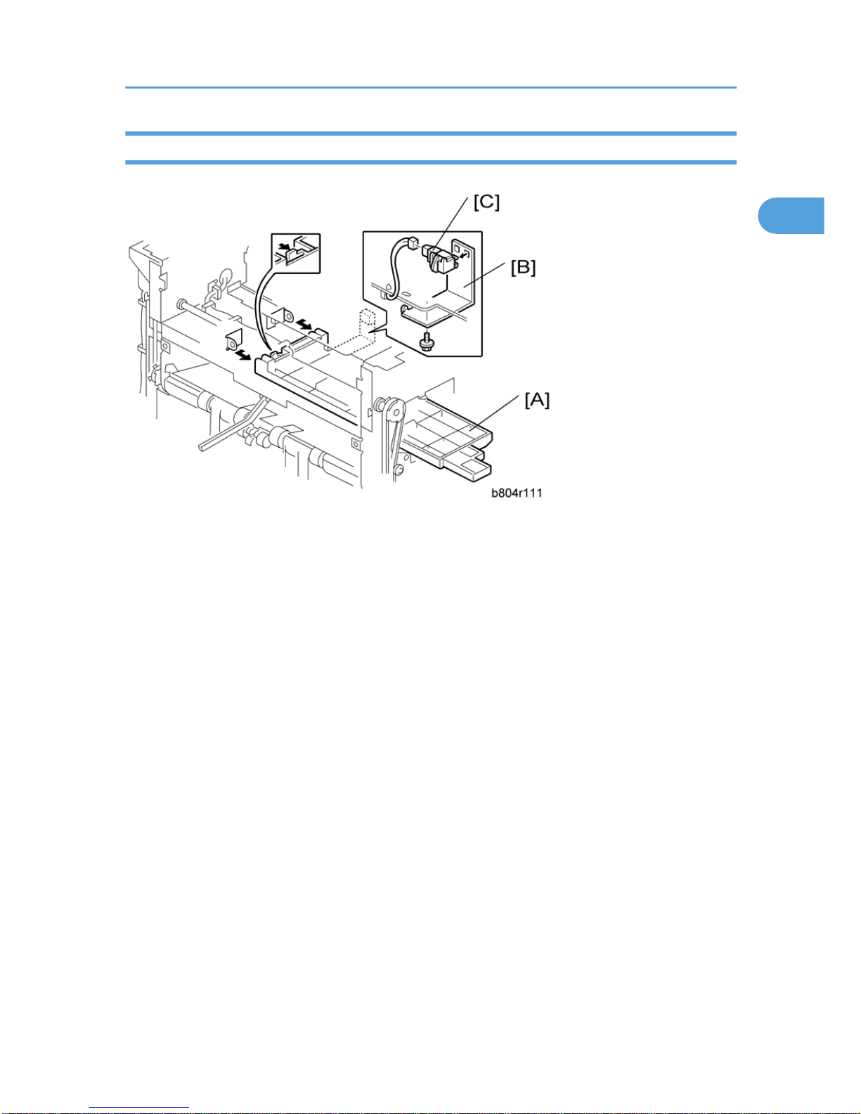
Stack Present Sensor
• If you intend to correct the horizontal and vertical skew for the fold unit at the same time, do those
adjustments first, then replace the sensor. (* "Folding Horizontal Skew Adjustment" or "Fold Vertical
Skew Adjustment")
1. Remove the stapler unit (* "Fold Unit")
2. Guide plate [A].
3. Stay [B] ( x4)
4. Left plate [C] ( x4)
5. Sensor bracket [D] ( x1)
6. Stack present sensor [E] (S32) ( x1)
1. Replacement and Adjustment
20
1
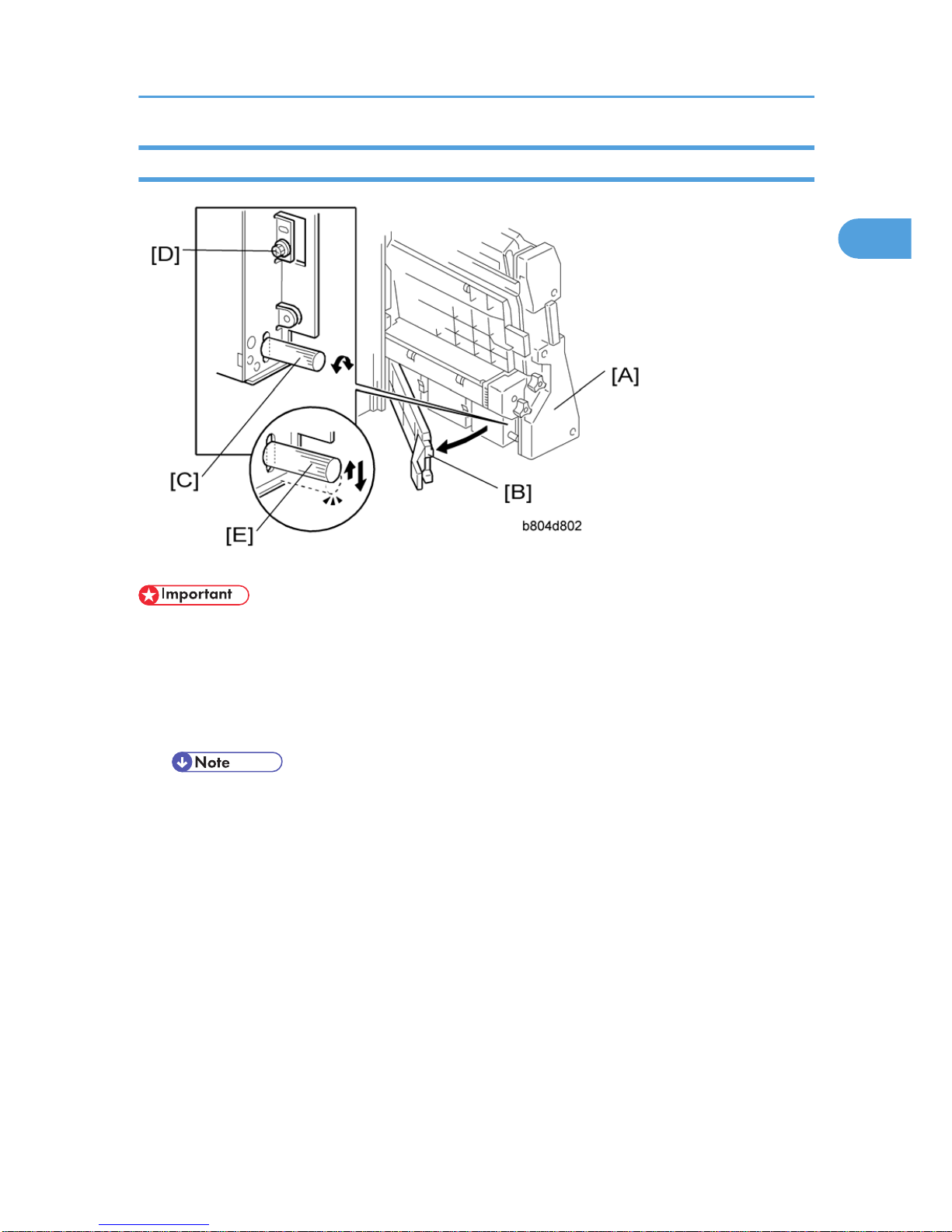
Folding Horizontal Skew Adjustment (For B804 only)
• The fold unit is adjusted for optimum performance before the finisher is shipped from the factory. Do
this adjustment only if the edges of folded booklets are not even.
1. Switch the copier on and enter the SP mode.
2. Europe, Asia: Use SP6-134-001 (this is for A3 paper). North America: Use SP6-134-005 (this is for
DLT paper).
• If the original setting of SP6-134-001 or -005 is not "0", then you must do the vertical skew
adjustment (* "Fold Vertical Skew Adjustment") after you finish this horizontal skew procedure.
3. Use the 10-key pad to input "-2" (mm) for the SP value. (Press to enter the minus sign.)
4. Press [#] then exit the SP mode.
5. Open the front door and pull the stapler unit [A] out of the finisher.
6. Open the guide plate [B].
7. Loosen the adjustment screw [C] and then tighten until it stops. (Do not over tighten.)
8. Remove the lock screw [D].
9. Raise the tip [E] of the adjustment screw very slightly and allow it to descend under its own weight.
Fold Unit
21
1
10. Push the stapler unit into the finisher and close the front door.
11. Do a folding test.
• Switch the copier on.
• Put one page of A3 or DLT paper in the ARDF.
• On the copier operation panel, select booklet stapling.
• Press [Start]. One sheet is folded.
12. Remove the sheet from the lower tray.
13. Hold the folded sheet with the creased side pointing down and face-up (the same way that it came
out of the finisher).
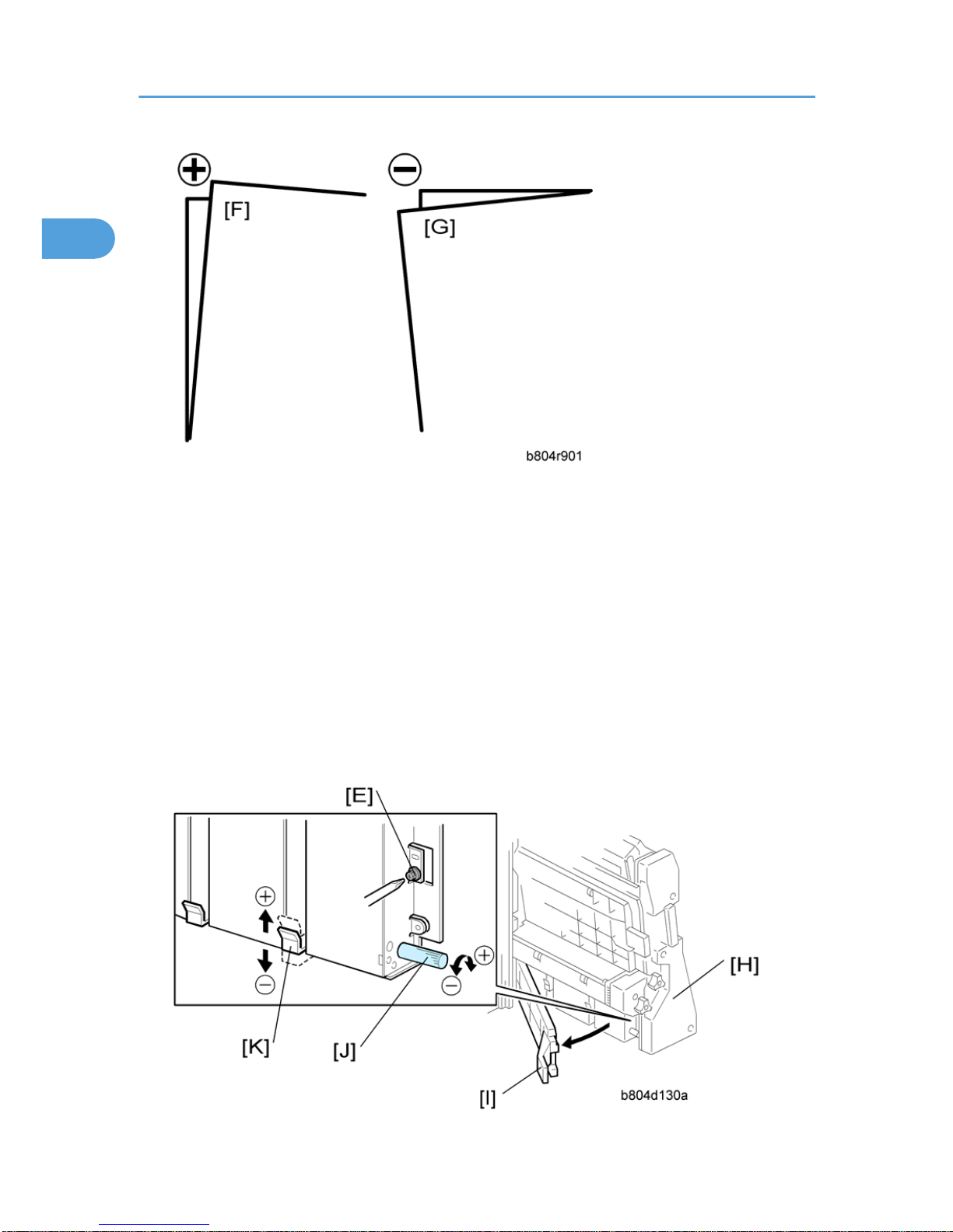
14. Referring to the diagram, determine if the skew is + [F] or - [G].
1. Replacement and Adjustment
22
1

15. Open the front door of the finisher and pull the stapler unit [H] out.
16. Open the guide plate [I].
17. Turn the adjustment screw [J] to correct the amount of skew you measured from the test sheet.
• For + skew [F], turn the adjustment screw (clockwise).
• For – skew [G], turn the adjustment screw to the left (counter-clockwise).
• Every click in the +/– direction adjusts the fold position by 0.1 mm by moving the bottom fence
[K].
18. Raise the tip of the adjustment screw [J] and allow it to lower under its own weight.
19. Attach and tighten the lock screw [L].
20. Push the stapler unit into the machine, close the front door, then turn the copier on.
21. Europe, Asia: Do SP6-134-001 (this is for A3 paper). North America: Do SP6-134-005 (this is for
DLT paper).
22. Reset it to "0".
23. Do the test again.
24. If the result is satisfactory, this completes the adjustment. -or- If some skew remains, repeat this adjustment.
• After doing this adjustment, adjust for vertical skew, if necessary. (* "Fold Vertical Skew Adjustment")
Fold Vertical Skew Adjustment (For B804 only)
• The fold unit is adjusted for optimum performance before the finisher is shipped from the factory. Do
this adjustment only if the edges of folded booklets are not even.
1. Switch the copier on.
2. Do a folding test.
• Switch the copier on.
• Put one page of A3 or DLT paper in the ARDF.
• On the copier operation panel, select booklet stapling.
• Press [Start]. One sheet is folded.
3. Hold the folded sheet with the creased side pointing down, and face-up (the same way that it came
out of the finisher).
Fold Unit
23
1
 Loading...