

Page 1

FINISHER
(A666)
Page 2

10 January 1997 OVERALL MACHINE I NFO R M ATI O N
1. OVERALL MACHINE INFORMATION
1.1 SPECIFICATIONS
Paper Size: Standard copying/Stack mode
Maximum: 11" x 17"/A3
Minimum: 5
(lengthwise)
Staple Mode
11" x 8
1/2
" (sideways)/A4 (sideways)
1/2
" x 8
1/2
" (lengthwise)/A6
Paper Weight: Standard copying/Stack mode
2
14 lb. ~ 42 lb. /52 g/m
~ 157 g/m2
(face-up mode)
17 lb. ~ 28 lb./64 g/m
2
~ 105 g/m
(face-down mode)
Staple Mode
2
17 lb. ~ 21 lb. /64g/m
~ 80g/m
Paper Capacity: Standard copying/Stack mode
250 sheets (face-up mode)
1/2
1000 sheets : 8
" x 11"/A4 or smaller
(21 lb. / 80g/m
mode)
500 sheets : 8
1/2
" x 14"/B4 or smaller
(21 lb. /80g/m
Staple Mode
30 sets (80 g/m, 20 pages per set)
Stapler Capacity: 2 to 20 sheets (21 lb. /80g/m
2
Staple Position: 1 position (Oblique)
2
2
2
)(face-down
2
) (face-down mode)
)
Staple Replenishment: Cartridge exchange (2,000 staples/cartridge)
Power Source: DC 24V, DC 5V (from the copier)
Power Consumption: 60W
Weight: 28 kg
Size: 520 x 550 x 750 mm
A666-1
Options
Page 3
OVERALL MACHINE INFORMATION 10 January 1997
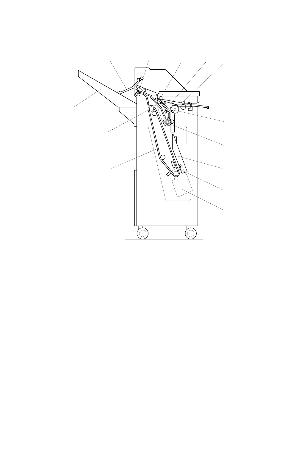
1.2 MECHANICAL COMPONENT LAYOUT
1
432
5
13
6
12
7
11
8
9
10
1. Stack Height Sensor Feeler
2. Exit Roller
3. Transport Roller
4. Junction Gate
5. Entrance Roller
6. Turn Roller
7. Alignment Roller
A666V500.wmf
8. Jogger Unit Guide
9. Stack Stopper
10. Stapler Unit
11. Feed-out Belt
12. Feed-out Roller Belt Drive
13. Shift Tray
A666-2
Page 4

10 January 1997 OVERALL MACHINE I NFO R M ATI O N
1.3 ELECTRICAL COMPONENT LAYOUT
22
21
20
19
18
1
2
3
4
5
6
7
8
9
17
16
15
1. Transport Motor
2. Junction Gate Solenoid
3. Upper Cover Open Sensor
4. Shift Tray Position Sensor
5. Entrance Motor
6. Shift Motor
7. Jogger Unit Set Switch
10
11
14
12
13
A666V501.wmf
12. Staple End Switch
13. Jogger Unit Paper Sensor
14. Jogger Motor
15. Jogger HP Sensor
16. Shift Tray Lift Motor
17. Feed Belt HP Sensor
18. Shift Tray Lower Limit Sensor
8. Finisher Drive Board
9. Feed-out Motor
10. Staple Motor
11. Hammer HP Sensor
19. Inverter Sensor
20. Entrance Sensor
21. Exit Sensor
22. Stack Height Sensor
A666-3
Options
Page 5

OVERALL MACHINE INFORMATION 10 January 1997
1.4 ELECTRICAL COMPONENT DESCRIPTION
Symbol Name Function Index No.
Motors
M1 Transport Drives the transport rollers and the exit roller.
M2 Shift Tray Lift Moves the shift tray up or down.
M3 Feed-out Drives the fee d- feed out belt.
M4 Jogger Moves the jogger fence.
M5 Entrance Drives t he entrance roller.
M6 Shift Moves the shift motor to front or rear.
M7 Staple Drives the staple hammer.
Sensors
S1 Entrance Detects the copy paper enterin g the finisher and
detects misfeeds.
S2 Inverter Detects the trailing edge of the paper to change the
rotation direc tion of the transpor t mo tor
S3 Jogger Unit
Paper
S4 Exi t Detects misfeed s in the exit area.
S5 Feed-out Belt HP Detects the ho m e position of the feed-out belt.
S6 Jogger HP Detects the jo gger home positio n.
S7 Shift Tray Lower
Limit
S8 Shift Position Detects the stop position of the shift motor.
S9 Stack Height Detects when the copy stack is prope r height.
S10 Upper Cover
Open
S11 Staple HammerHPDetects the hom e position of the stapl e hammer.
Detects the paper in the jogger unit and detects
misfeeds.
Detects the lower limit position of the shift tray.
Detects whether the upper cover is opened or not.
Switches
SW1 Jogger Unit Set Cuts the +24V power withi n the finisher when the
jogger unit is pul l ed out.
SW2 Staple End Detects when the staples have run out.
Solenoid
SOL1 Junction Gate Drives the junction gate.
PCBs
PCB1 Finisher Drive Controls overall f i nisher operation .
A666-4
Page 6
10 January 1997 OVERALL MACHINE I NFO R M ATI O N
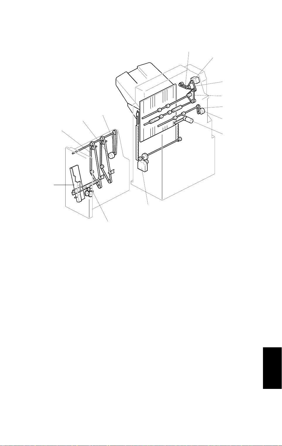
1.5 DRIVE LAYOUT
1
2
3
4
12
13
11
10
1. Exit Roller Driv e Belt
2. Transport Motor
5
6
7
8
A666V502.wmf
9
8. Shift Tray Lift Motor
9. Jogger Motor
3. Transport Drive Belt
4. Inverter Drive Belt
5. Entrance Drive Belt
6. Entrance Motor
7. Shift Motor
10. Jogger Fence
11. Stack Feed Belt
12. Feed-out Motor
13. Feed-out Drive Belt
Options
A666-5
Page 7
DETAILED DESCRIPTION S 10 January 1997
2. DETAILED DESCRIPTIONS
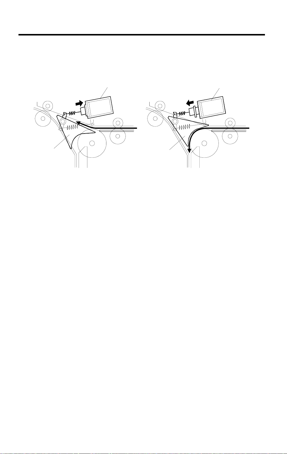
2.1 JUNCTION GATE MECHANISM
[B]
[A]
[B]
[A]
A666D500.wmf
When the entrance sensor is activated in face-up mode, the junction gate
solenoid [A] turns on and the junction gate [B] is closed. Then, the paper is
transported directly to the shift tray and its maximum speed is 180 mm/s.
When the entrance sensor is activated in face-down or staple mode, the
junction gate solenoid [A] stays off and the junction gate [B] is open. Then the
paper is transported to the jogger unit.
A666-6
Page 8
10 January 1997 DETAILED DESCRIPTIO NS
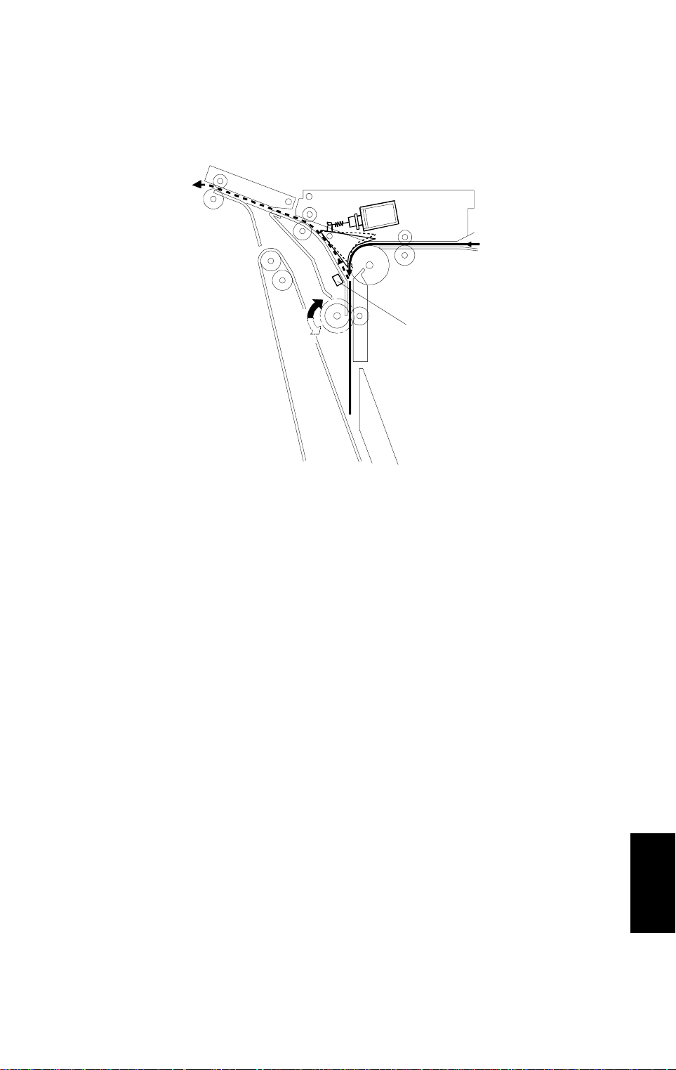
2.2 PAPER REVERSING MECHANISM
[A]
A666D501.wmf
The paper is sent to the staple unit when face-down mode is selected. The
paper is transported to the staple unit at 180 mm/s until the trailing edge of
the paper turns off the copier exit sensor. After the exit sensor is turned off,
the paper transport speed is changed to 500 mm/s.
When the trailing edge of the paper passes through the inverter sensor [A],
the transport motor turns off. Then, the transport motor turns on in reverse
and the paper is transported to the shift tray.
A666-7
Options
Page 9
DETAILED DESCRIPTION S 10 January 1997
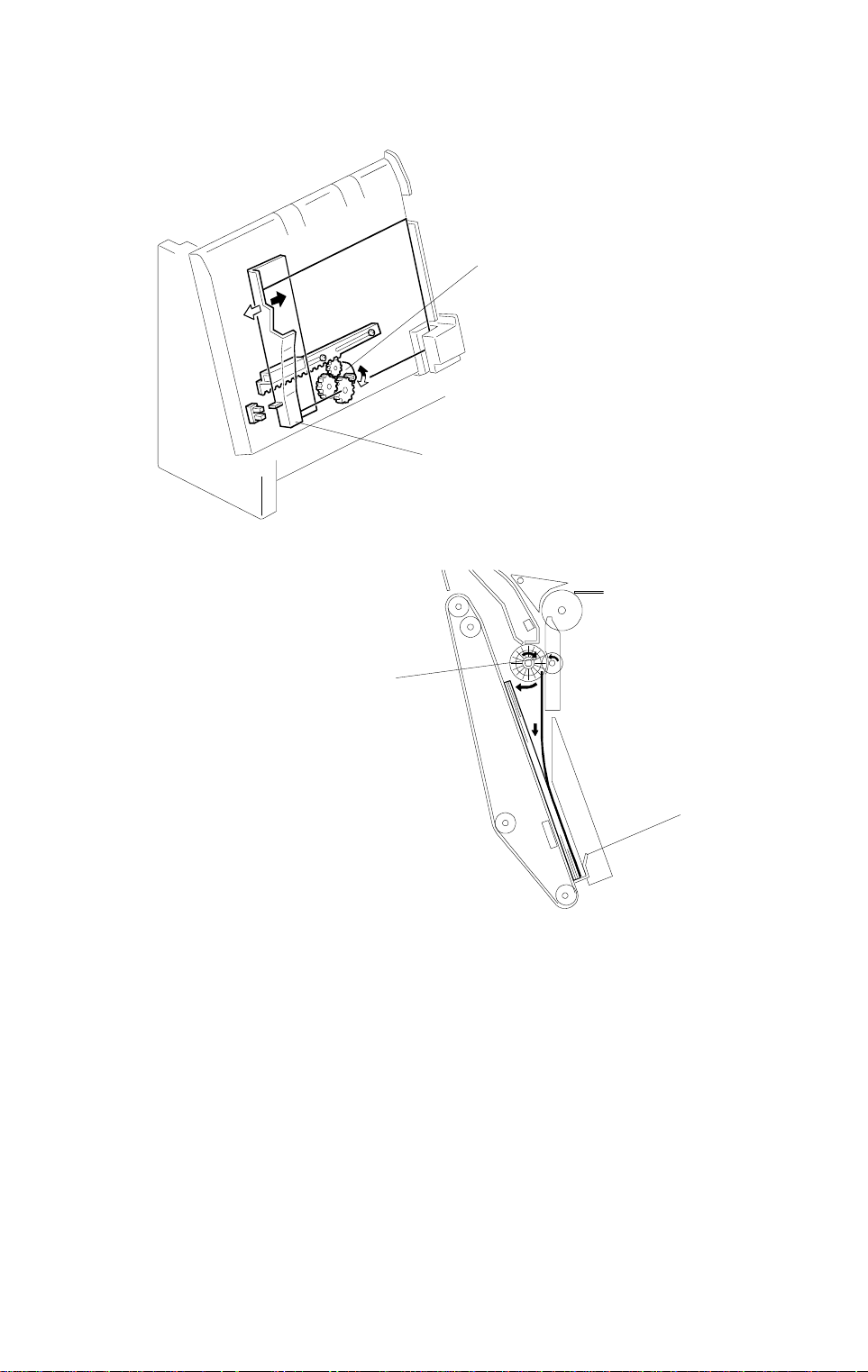
2.3 JOGGER UNIT PAPER POSITIONING MECHANISM
[A]
[B]
A666D503.wmf
[C]
[D]
A666D502.wmf
In staple mode, each sheet of copy paper is vertically and horizontally
aligned when it arrives in the jogger unit.
For the horizontal alignment, the jogger motor [A] moves the front jogger
fence [B] to align the copies.
For the vertical alignment, the brush roller [C] pushes the trailing edge of the
paper against the stack stopper [D]. The position of the stack stopper
depends on the paper size (LT or A4), and is changed by the feed-out motor.
A666-8
Page 10
10 January 1997 DETAILED DESCRIPTIO NS
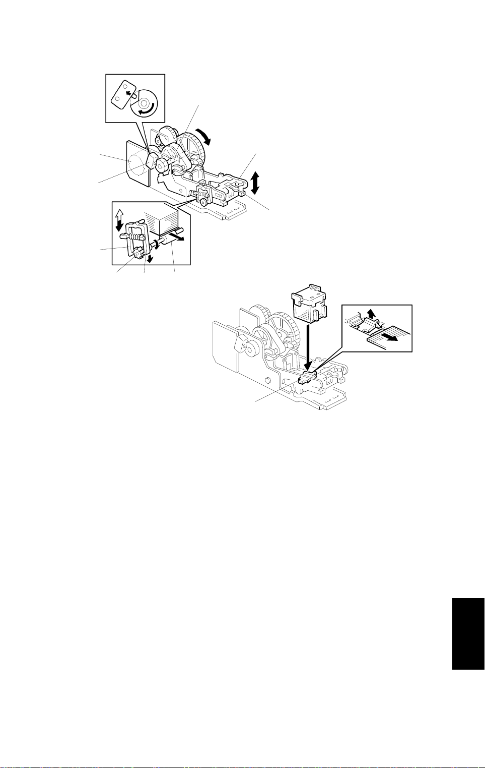
2.4 STAPLER
[C]
[B]
[A]
[D]
[J]
[G]
A666D508.wmf
[E] [H]
[F]
[I]
A666D504.wmf
The staple hammer [A] is driven by the stapler motor [B] via gears, a
eccentric cam [C].
When the aligned copies are brought to the stapling position by the brush
roller and jogger fence, the stapler motor [B] turns on. When the cam [C]
completes one rotation, the staple hammer home position sensor [D] turns
off, detecting the end of the stapling operation. The staple motor then turns
off.
The feed gear [E] drives staple feed roller [F] to feed a sheet of staples. The
feed gear is driven by the long hook [G] when the hammer moves up and by
the short hook [H] when the hammer moves down.
When there is only one sheet of staples left in the cartridge, the actuator [I]
moves up and the staple end sensor is activated.
When jammed staples are left in the staple unit, release and move up the
staple guide [J] to remove the jammed staples.
Options
A666-9
Page 11

DETAILED DESCRIPTION S 10 January 1997
2.5 FEED OUT MECHANISM
[C]
[B]
[A]
[D]
A666D505.wmf
After the copies have been stapled, the feed-out motor [A] turns on to drive
the feed out belt. The stack stopper [B] on the feed-out belt transports the set
of stapled copies up,(its speed is 450 mm/s) and feeds it towards the shift
tray. Approximately 500 ms after the feed-out motor turns on, it stops for 500
ms. At this moment, the exit roller [C] catches the stapled copies to feed them
out to the shift tray. Then, the feed-out motor turns on again until the stack
stopper actuates the feed-out belt home position sensor [D].
The transport motor drives the brush roller and the exit roller [C] (speed 500
mm/s). The transport motor turns on when the feed-out motor turns on at the
start of feed-out to drive brush roller. This prevents the brush roller from
disturbing the smooth upward passage of the leading edge of the copy set at
the start of paper feed. After 200 ms, the transport motor turns off and on
again in reverse to feed out the set of staple copies.
A666-10
Page 12

10 January 1997 DETAILED DESCRIPTIO NS
2.6 SHIFT TRAY UP/DOWN MECHANISM
[F]
[E]
[G]
[B]
[A]
[H]
[C]
[D]
A666D506.wmf
The shift tray lift motor [A] controls the vertical position of the shift tray [B]
through the gears [C,D]. When the main switch is turned on, the tray is
initialized at the upper position. The trays upper position is detected when the
shift tray pushes up actuator feeler[E] until the actuator turns on the stack
height sensor [F]. Then the shift tray lift motor turns in reverse until the stack
height sensor turns off.
During copying, the actuator feeler [E] gradually rises as the copy stack
grows. When the stack height sensor [F] turns on, the shift tray lift motor
lowers the shift tray [B] until the sensor is off.
When the actuator [G] turns off the lower limit sensor [H], copying stops. After
copying ends and machine is stopped and the copies are removed, the shift
tray rises until the stack height sensor [F] is on. Then the shift tray lift motor
turns in reverse until the stack height sensor turns off.
Options
A666-11
Page 13

DETAILED DESCRIPTION S 10 January 1997
2.7 SHIFT TRAY SIDE-TO-SIDE MECHANISM
[E]
[C]
[A]
[F]
[B]
[D]
[B][F]
A666D507.wmf
The horizontal position of the shift tray is controlled by the shift motor [A] and
the shift motor disk [B]. After one set of originals is copied and delivered to
the shift tray [C], the shift motor turns on, driving the shift motor disk and the
lever [D]. The shift tray base plate [E] is positioned by the lever, creating the
side-to-side movement required to stagger the copies.
When the shift motor disk [B]has rotated 180 degrees (when the shift tray is
fully shifted across), the cut-out in the shift motor disk turns on the shift
position sensor [F] and the shift motor [A] stops. The next set of copies is
then delivered. The motor turns on, repeating the same process and moving
the tray back to the previous position.
A666-12
Page 14

10 January 1997 DETAILED DESCRIPTIO NS
2.8 TIMING CHART
2.8.1 Face-up Mode (A4: 2 sheets)
0123456
COPIER FINISHER
START
Shift ON
Exit Sensor
FINISHER COPIER
Complete Paper Exit
FINISHER
Entrance Sensor
0.25s
Exit Sensor
Shift Home Sensor
Stack Height Sensor
Entrance Motor
Transport Motor
Junction Gate Solenoid
Shift Motor
Shift Tray Lift
20 cpm
25 cpm
A666D510.wmf
A666-13
Options
Page 15

DETAILED DESCRIPTION S 10 January 1997
2.8.2 Face-down Mode (A4: 2 sheets)
0123456
COPIER FINISHER
START
Exit Sensor
FINISHER COPIER
Complete Paper Exit
FINISHER
Entrance Sensor
0.25s
Inverter Sensor
Exit Sensor
Shift Position
Stack Height Sensor
Entrance Motor
Transport Motor
Shift Motor
Shift Tray Lift Motor
20 cpm
25 cpm
A666D509.wmf
A666-14
Page 16

10 January 1997 DETAILED DESCRIPTIO NS
2.8.3 Staple Mode (A4: 2 sheets)
COPIER FINISHER
START
Staple ON
Exit Sensor
FINISHER COPIER
Complete Paper Exit
FINISHER
Entrance Sensor
Inverter Sensor
Exit Sensor
Shift Home Sensor
Stack Height Sensor
Jogger Unit
Paper Sensor
Hammer HP Sensor
Entrance Motor
0
12345678
0.50s
0.50s
0.40s
Transport Motor
Jogger Motor
Feed-out Motor
Staple Motor
Shift Motor
Shift Tray Lift Motor
20 cpm
25 cpm
A666D511.wmf
Options
A666-15
Page 17

DETAILED DESCRIPTION S 10 January 1997
2.8.4 Jam Detection
1. Face-up Mode
Jam 1:
Jam 2:
Jam 3:
The entrance sensor stays on for 4.2 s.
The exit sensor stays off 3.5 s after the entrance sensor turns on.
The exit sensor stays on for 2.0 s.
2. Face-down Mode
Jam 1:
Jam 2:
Jam 3:
Jam 4:
Jam 5:
The entrance sensor stays on for 4.2 s.
The inverter sensor stays off 1.5 s after the entrance sensor turns on.
The inverter sensor stays on for 4.2 s.
The exit sensor stays off 0.6 s after the inverter sensor turns off.
The exit sensor stays on for 1.2 s.
3. Staple Mode
Jam 1:
Jam 2:
Jam 3:
Jam 4:
The entrance sensor stays on for 2.5 s.
The inverter sensor stays off 1.5 s after the entrance sensor turns on.
The inverter sensor stays on for 0.8 s.
The jogger unit paper sensor stays off 0.5 s after the inverter sensor
turns off.
Jam 5:
Jam 6:
Staple Jam:
The exit sensor stays off 1.05 s after the feed-out motor turns on.
The exit sensor stays on for 0.85 s.
The staple hammer HP sensor stays off 0.48 s after the staple
motor turns on.
A666-16
Page 18

10 January 1997 DETAILED DESCRIPTIO NS
2.8.5 Verall Electrical Circuit
Finisher Drive Baord
Motors
Main
Frame
/TXD
/RSD
Finisher
Connection
Solenoid
Sensors
Switches
A666D512.wmf
All components (motors, sensors, solenoid and switches) are controlled by
the finisher drive board and the communication between the main frame and
finisher uses a serial signal.
When the finisher is connected, the finisher connection signal to the main
frame is grounded. Then the main frame detects that the finisher is
connected.
A666-17
Options
Page 19

INSTALLATION PROCEDURE 10 January 1997
3. INSTALLATION PROCEDURE (AD1/AD1E)
A666I507.wmf
A666I505.wmf
CAUTION
+
A666I500.wmf
A666i501.wmf
Unplug the copier power cord and turn off the main switch before
starting the following procedure.
1. Unpack the finisher. Then remove all tapes and cushions.
A666-18
Page 20

10 January 1997 INSTALLATION PROCEDURE
[B]
[C]
[D]
[A]
[E]
A666I502.wmf
[F]
[G]
A666I506.wmf
2. Push the hook [A] of the face-up tray shaft cover [B] and remove it.
3. Remove the face-up tray [C].
4. Remove the caps [D] and the connector cover [E].
5. Peel off the backing of the double sided tapes [F] of the grounding plate
[G].
6. Insert the grounding plate between the copier and the paper bank as
shown.
Options
A666-19
Page 21

INSTALLATION PROCEDURE 10 January 1997
[B]
[A]
A666I503.wmf
[D]
[F]
[E]
[C]
A666I504.wmf
7. Install the front [A] and rear [B]connecting bracket. (2 screws each)
8. Pull out the stapler unit [C] and confirm that locking lever [D] has been
drawn out.
9. Align and install the finisher to connecting brackets and lock them in
place by pushing the locking lever [D].
10. Secure the locking lever [D] (1 screw) and push the staple unit into the
finisher.
11. Install the shift tray [E] (1 snap ring).
12. Connect the cable [F]to the copier.
13. Plug in the copier power cord.
14. Turn the ac and main switches on. and check if the document feeder
works properly.
A666-20
Page 22

10 January 1997 PREVENTIVE MAINTENANCE
4. PREVENTIVE MAINTENANCE
NOTE:
The amounts mentioned as the PM interval indicate the number of
prints.
Symbol key: C:Clean , R:Replace , L:Lubricate , I:Inspect
ITEM EM 100K 200K 300K NOTE
RollersCCCCAlcohol or water
Bushings
SensorsCCCCDry cloth
IIII
Use Launa oil or
equivalent
A666-21
Options
Page 23

SERVICE TABLES 10 January 1997
5. SERVICE TABLES
5.1 LED TABLE
LED No. 100 LED No. 101 FUNCTION
ON OFF When the entrance sensor is ON (Paper Detected)
OFF ON When the inver t er sensor is ON (Paper Detected)
ON ON When the exit sensor is ON (Paper Detected)
NOTE:
Check the sensors by setting DIP SW 100/101 to Sensor Check
Mode(see below).
5.2 DIP SWITCH TABLE
5.2.1 Factory Setting
[ 0 : OFF 1 : ON ]
DIP SW 100 DIP SW 101
43214321
00000000
5.2.2 Stapling Position Adjustment
[ 0 : OFF 1 : ON ]
DIP SW 100 DIP SW 101 STAPLING POSITION
43214321
0 0 0 0 0 0 0 1 + 1.0 mm (down)
0 0 0 0 0 0 1 0 + 2.0 mm (down)
00000100–1.0 mm (up)
00001000–2.0 mm (up)
5.2.3 Sensor Check
[ 0 : OFF 1 : ON ]
DIP SW 100 DIP SW 101
43214321
10000000
When checking the sensors , see the LED table (5.1).
A666-22
Page 24

10 January 1997 SERVICE TABLES
5.2.4 FREE RUN WITHOUT PAPER
How to do a free run
1. Turn off the main and AC switches, and unplug the machine.
2. Select the free run mode with DIP switches (see below).
3. Disconnect connector 102 on the finisher drive board.
4. Plug in the machine and turn on the power (AC and main switches).
5. To stop the free run, pull out the staple unit.
DIP SW 100 DIP SW 101 FUNCTION
43214321
0 1 1 1 0 0 0 0 Staple Mo de (2 Pages)
0 1 1 1 0 0 0 1 Staple Mode ( 5 Pages)
0 1 1 1 0 0 1 0 Staple Mo de (10 Pages)
0 1 1 1 0 1 0 0 Staple Mo de (15 Papers)
0 1 1 1 1 0 0 0 Staple Mo de (20 Pages)
11110000Face Down Mode (2 Pages)
11110001Face Down Mode (5 Pages)
11110010Face Down Mode (10 Pages)
11110100Face Down Mode (15 Pages)
11111000Face Down Mode (20 Pages)
A666-23
Options
Page 25

REPLACEMENT AND ADJUSTMENT 10 January 1997
6. REPLACEMENT AND ADJUSTMENT
6.1 EXTERIOR REMOVAL
[I]
[E]
[B]
[A]
[H]
[B]
[I]
[G]
[C]
[D]
A666R500.wmf
1. Remove the shift tray [A] (1 snap ring).
NOTE :
The shift tray cannot be removed if it is at its uppermost position.
2. Remove the rear cover [B] (3 screws).
3. Remove the front cover [C] (2 screws).
4. Remove the front inner cover [D] (3 screws).
5. Remove the upper cover [E] (2 screws).
6. Remove the rear upper cover [F] (1 screw).
7. Remove the upper entrance cover [G] (2 screws).
8. Remove the front and rear tray covers [H,I] (2 screws)
9. Remove the left cover [J](2 screws).
A666-24
Page 26

10 January 1997 REPLACEMENT AND ADJUSTMENT
6.2 ALIGNMENT BRUSH ROLLER REPLACEMENT
[A]
[B]
[C]
[A]
[D]
[C]
A666R501.wmf
1. Remove the front and rear covers.
2. Pull out the jogger unit
3. Remove the E-ring [A], slide off the pulley [B], then remove 2 bushings
[C].
NOTE:
When reinstalling, the metal bushing goes at the front side.
4. Remove the alignment brush roller assembly [D].
A666-25
Options
Page 27

REPLACEMENT AND ADJUSTMENT 10 January 1997
6.3 BELT TENSION ADJUSTMENT
[A]
[C]
[B]
A666R502.wmf
1. Remove the rear cover.
2. Loosen the 2 screws [A] of the transport motor bracket and tighten them
again to adjust the two tension belts [B,C].
A666-26
Page 28

10 January 1997 REPLACEMENT AND ADJUSTMENT
6.4 STACK HEIGHT SENSOR REPLACEMENT
[A]
[B]
1. Remove the front, rear, and upper covers.
2. Remove the stack height sensor actuator [A] (1 screw).
3. Replace stack height sensor [B] (1 connector).
A666R503.wmf
A666-27
Options
Page 29

REPLACEMENT AND ADJUSTMENT 10 January 1997
6.5 EXIT SENSOR REPLACEMENT
[B]
[C]
[A]
A666R504.wmf
1. Remove the front, rear, and upper covers.
2. Remove the exit guide unit [A] (1 screw).
3. Remove the discharge brush and the exit guide plate [B] (2 screws).
4. Remove the exit sensor [C] (1 screw and 1 connector).
A666-28
Page 30

10 January 1997 REPLACEMENT AND ADJUSTMENT
6.6 INVERTER SENSOR REPLACEMENT
[A]
A666D505.wmf
[B]
1. Remove the front, front inner, and rear covers.
2. Slide out the jogger unit.
3. Remove the entrance guide plate [A] (4 screws).
4. Remove the inverter sensor ass’y [B] (1 screw and 1 connector).
5. Replace the inverter sensor.
A666-29
Options
Page 31

FNISHER (A666) ELECTRICAL COMPONENT LAYOUT
22
1
21
20
19
18
17
2
3
4
5
6
7
8
9
10
11
16
15
12
13
14
A666S501.WMF
Page 32

Symbol Index No. Function P to P
Motors
M1 1 Transport D13
M2 16 Shift Tray Lift F13
M3 9 Feed-out H13
M4 14 Jogger G13
M5 5 Entrance B13
M6 6 Shift E13
M7 10 Staple J14
Sensors
S1 20 Entrance E4
S2 19 Inverter F4
S3 13 Jogger Unit Paper K5
S4 21 Exit I4
S5 17 Feed-out Belt HP J5
S6 15 Jogger HP J5
S7 18 Shift Tray Lower Limit G4
S8 4 Shift Position G4
S9 22 Stack Height H4
S10 3 Upper Cover Open E4
S11 11 Staple Hammer HP J13
Switches
SW1 7 Jogger Unit Set K12
SW2 12 Staple End I13
Solenoid
SOL1 2 Junction Gate A13
PCB
PCB1 8 Finisher Drive B8
2
Page 33

(
)
12345678910111213141516
A
FINISHER (A666) POINT TO POINT DIAGRAM
B
C
D
Upper Cover Open
E
F
Shift Tray Lower Limit
G
Shift Position Sensor
H
Stack Height Sensor
I
SYMBOL TABLE
J
▼
▲
[ ] Voltage
K
Main Machine
Senosr
Entrance Sensor
Inverter Sensor
Sensor
Exit Sensor
DC Line
Pulse Signal
Signal Direction
Active Low
Active High
[+24 V]
[+24 V]
[+24 V]
[+24 V]
NC
GND
GND
GND
GND
GND
NC
[+5 V]
Finisher Set [▼5]
/TXD [▼5]
/RXD [▼5]
Stop [▼5]
GND
GND
-1
CN221
S10
S1
S2
S7
S8
S9
S4
-2
-3
-1
-2
-3
-1
-2
-3
-1
CN205
-2
-3
-1
-2
-3
-1
-2
-3
-1
CN213CN223CN204CN212CN211
-2
-3
Feed-out Belt H.P
Sensor
Jogger H.P Sensor
Jogger Unit Paper
Sensor
CN2-12
-11
-10
CN1-11
-10
-9
-8
-7
-6
-5
-4
-3
-2
-1
-9
-8
-3
-1
-6
-5
-4
-3
-2
-1
-3
-2
-6
-5
-4
-3
-2
-1
CN202CN201
CN203
S5
S6
S3
-1
-2
-3
-4
-5
-6
-1
-2
-3-1
-1
-2
-3
-4
-5
-6
CN207CN208
CN206
-1
-2
-3
-1
-2
-3
-1
-2
-3
CN101-12
-11
-10
CN102-6
CN104-6
CN105-3
CN106-13
-12
-11
-10
CN107-10
[+24 V]
[+24 V]
[+24 V]
-9
[+24 V]
-8
NC
-7
GND
-6
GND
-5
GND
-4
GND
-3
NC
-2
GND
-1
[+5 V]
[▼5] Finisher Set
-5
[▼5] /TXD
-4
[▼5] /RXD
-3
[▼5] Stop
-2
GND
-1
GND
[+5 V]
-5
[▼5] Upper Cover Option
-4
GND
-3
[+5 V]
-2
[▼5] Entrance
-1
GND
[+5 V]
-2
[▲5] Inverter
-1
GND
[+5 V]
[▲5] Shift Tray Lower Limit
GND
[+5 V]
-9
[▼5] Shift Position
-8
GND
-7
NC
-6
[+5 V]
-5
[▲5] Stack Height
-4
GND
-3
GND
-2
[▲5] Exit
-1
[+5 V]
NC
-9
[+5 V]
-8
GND
-7
[▼5] Feed-out Belt H.P
-6
[+5 V]
-5
[▲5] Jogger H.P
-4
GND
-3
GND
-2
[▲5] Jogger Unit Paper
-1
[+5 V]
Finisher Drive
Junction Gate [▼24]
PCB 1
Shift Tray Lift (+) [▲24]
Shift Tray Lift (-) [▲24]
Stapler Unit Set [▼5]
Staple Hammer H.P [▼5]
Jogger Unit Set [▲24]
[+24 V]
[+24 V]
[+24 V]
NC
A [▼24]
/A [▼24]
B [▼24]
/B [▼24]
[+24 V]
[+24 V]
NC
A [▼24]
/A [▼24]
B [▼24]
/B [▼24]
Shift (+) [▲24]
Shift (-) [▲24]
[+24 V]
A [▼24]
/A [▼24]
B [▼24]
/B [▼24]
[+24 V]
[+24 V]
[+24 V]
NC
A [▼24]
/A [▼24]
B [▼24]
/B [▼24]
GND
Staple End [▼5]
GND
Staple (-) [▲24]
Staple (-) [▲24]
Staple (+) [▲24]
Staple (+) [▲24]
[+24 V]
CN110-1 -1
-2
CN111-1
-2
-3
-4
-5
-6
-7
CN112-1
-2
-3
-4
-5
-6
-7
CN113-1
-2
CN114-1
-2
CN115-1
-2
-3
-4
-5
-6
CN116-1
-2
-3
-4
-5
-6
-7
CN108-9
CN103-1
-1
-2
-8
-3
-7
-4
-6
-5
-5
-6
-4
-7
-3 -3
-2
-8
-1 -1
-9
-2
-2
-1 -2
-7
-6
-5
-4
-3
-2
-1
-7
-6
-5
-4
-3
-2
-1
-2
-1 -2
-2
-1 -2
-6
-5
-4
-3
-2
-1
-7
-6
-5
-4
-3
-2
-1
-9
-8
-7
-6
-5
-4
CN309
-2
CN300
CN301
CN302
CN303
CN304
CN305
CN306
-1
-2
-3
-4
-5
-6
-7
-1
-2
-3
-4
-5
-6
-7
-1
-1
-1
-2
-3
-4
-5
-6
-1
-2
-3
-4
-5
-6
-7
CN209-1
SW1
M5
M1
M6
M2
M4
Stapler Unit
-2
-3
-4
-5
-6
-7
Junction Gate Sol.SOL1
Entrance Motor
Transport Motor
Shift Motor
Shift Tray Lift Motor
Jogger Motor
Feed-out MotorM3
SW2
S11
M7
Staple End SW
Staple Hammer
H.P Sensor
Staple Motor
Jogger Unit Set Switch
A
B
C
D
E
F
G
H
I
J
K
12345678910111213141516
 Loading...