

Page 1

FILM PROJECTOR UNIT
(Machine Code: A718)
Page 2

10 May 1996 SPECIFICATIONS
1. SPECIFICATIONS
Acceptable Film Types: • Type:Positive film/Negative film
• Size: 35 mm - Approx. 140 x 210 mm
Others: 45 x 60 mm, 60 x 60 mm,
60 x 70 mm, 60 x 80 mm,
60 x 90 mm, 4" x 5"
Max: 142 x 210 mm or 5.6" x 8.2"
• Mount: Yes (Up to 5 frames can be set in the
film holder.)
• Strip: Yes (A series of 6 frames can be
set in the film holder.)
Focusing: Fixed/Manual
Effective Film Area: • 35 mm: Approx. 21.5 x 33.0 mm
• Other Sizes: Full Size
Projection Ratio • 35 mm: Approx. x 6
• Other Sizes: x 1
Copy Image Size • 35 mm mount:120.8 x 192.7 mm
• 35 mm strip: 129.3 x 198.6 mm
• Other Sizes: Full Size
All the reproduction fea tures of the copie r are ava ilab le.
Power Source: 115 V 60 Hz, more than 1.0 A
220 ~ 240 V 50/60 Hz, more than 0.6 A
Power Consumption: Maximum: less than 185 VA
Dimensions (W x D x H): Projector: 300 x 442 x 212 mm
11.8" x 17.4" x 8.35"
Mirror Unit: 298 x 232 x 50 mm
11.73" x 9.13" x 1.97"
Weight: Projector: 10 kg, 22.1 lb
Mirror unit: 5 kg, 11.1 lb
Remarks: The holder is required for installa tio n.
A718-1
Options
Page 3
2
6
ELECTRICAL COMPONENT LAYOUT AND DESCRIPTIONS 10 May 1996
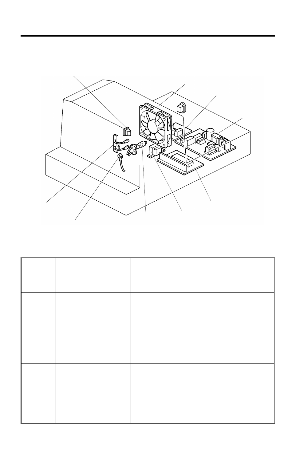
2. ELECTRICAL COMPONENT LAYOUT AND
DESCRIPTIONS
1
3
4
9
8
7
5
A718V500.img
Symbol Name Function
PCB1
PCB2
PCB3
M1 Lamp Cooling Fan Blows air to the projector lamp section. 2
SW1 Projector Switch Provides power to the projector unit. 1
L1 Projector Lamp Applies light to the film for exposure. 7
TH1
TF1
TR1
Projector Lamp Regulator Supplies dc voltage to the projector lamp
and lamp cooling fan.
Projector Control Board Controls the projector unit,
communicating with the copier main
board.
Noise Filter Board
(220–240V machine only)
Lamp Thermistor Detects the temperature around the
Lamp Thermofuse Opens the projector lamp circuit if the
Transformer
Removes electrical noise.
projector lamp to control the lamp
cooling fan.
projector lamp section overheats.
Steps down the wall voltage to 17 ∼ 18 V
ac.
Index
No.
4
5
3
8
9
6
A718-2
Page 4
10 May 1996 SECTIONAL DESCRIPTIONS
3. SECTIONAL DESCRIPTIONS
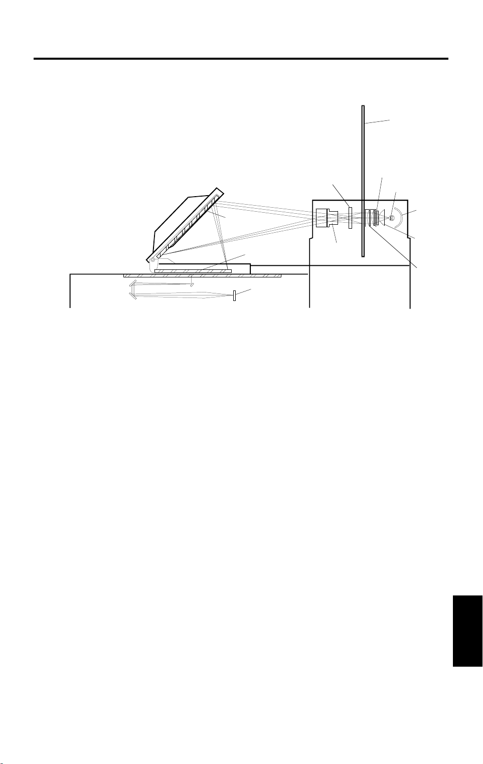
3.1 OVERVIEW
[H]
[G]
[C]
[E]
[A]
[B]
[D]
[J]
[I]
[F]
[K]
A718D500.wmf
This film projector unit allows making copie s from the followin g kind s of films:
35 mm positive slides (both mount films and glass mount films)
35 mm negative or positive strip films
Positive or negative films of wide size
(45 x 60 / 60 x 60 / 60 x 70 / 60 x 80 / 60 x 90 mm / 4" x 5" /
maximum size of 142 x 210 mm or 5.6" x 8.2")
The light from the projector lamp [A] is reflect ed by the refle cto r [B] and
reaches the film (35 mm) in the film/slide holder [C] through the non-spherical
lens [D], heat filter [E], and cond enser len ses [F]. The projected film image
reaches the mirror [G] through the correctio n filt er (po sitive or negat ive) [H]
and projection lens [I]. Then the mirror re fle cts th e image on to the expo sure
glass through the Fresnel lens [J]. The first scanner moves under th e
exposure glass to read the project ed film image and the light of the image is
converted to R/G/B elect rical sign als by th e CCD [K] .
The 35 mm film’s image is enlarged about 6 times when projected onto the
exposure glass.
In the case of wide films, the first scanner reads the film placed on the
exposure glass directly using the lig ht from th e pro ject or lamp .
The lamp cooling fan turns on and off depending on the temperature of the
projector lamp section dete cte d by the lamp thermistor. It turns on at around
45°C and turns off at around 44°C.
Options
A718-3
Page 5

SECTIONAL DESCRIPTIONS 10 May 1996
3.2 SHADING
When the projector un it is select ed , shading should be done aft er sele ctin g
the type of film. The shading should be done with a base film and the
N-correction filter for the negative films and with the P-correction filter
(without base film) for the positive films.
The N-correction filter corrects the color and inten sity of the proje cte d ligh t.
The P-correction filter corrects the ligh t int ensity of the proje cte d light so th at
it becomes similar to that for the negative films.
When "Shading" is performed , th e first scann er move s and stops und er th e
mirror unit. Then AGC (Auto Gain Control) for the light intensity from the
projector lamp is performed. Sh ad ing for bla ck and white levels is also
performed after th e AG C.
This "Shading" should be performe d whe never th e typ e of film is chang ed or
the mirror unit is moved.
A718-4
Page 6
[B]
[F]
Main scan
direction
10 May 1996 SECTIONAL DESCRIPTIONS
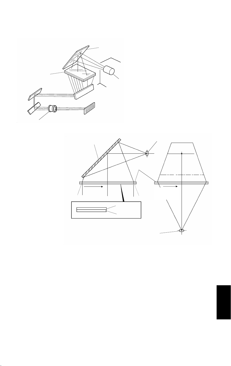
3.3 MIRROR UNIT
[C]
[B]
[A]
[F]
A718D501.img
[C]
[A]
Subscan
direction
[D]
[E]
A718D502.img
The film image projected through the projectio n len s [A] is reflect ed to the
Fresnel lens [B] by the mirror [C].
The Fresnel lens consists of two components, a circle pitch Fresnel lens [D]
and a parallel pitch Fresnel lens [E]. The circle pitch Fresnel lens changes
the divergent light to paralle l light. The parallel Fresnel lens collect s the light
from the circle pitch Fresnel lens in the main scan directio n so that all the
light reaches the color CCD lens [F].
The use of these two types of Fresnel lens makes the most of the ligh t
intensity from the projector lamp.
Options
A718-5
Page 7

10 May 1996 FILM PROJECTOR UNIT (A718) INSTALLATION
8. FILM PROJECTOR UNIT (A718)
INSTALLATION
8.1 ACCESSORY CHECK
Make sure that each accessory listed in the following table is in the bo x. Also
check the condition of ea ch ite m.
1. Mirror Unit........................................................................... 1
2. Power Cord ......................................................................... 1
3. Optical Fiber Cable............................................................. 1
4. Film Strip Holder............ .. ............ ................................ ....... 1
5. Slide Holder........................................................................ 1
6. Glass Mount Holder............................................................ 1
7. Base Film (FUJI, KODAK, AGFA)...................................... 3
8. Slide Mount......................................................................... 1
9. Correction Filter (P, N)........................................................ 2
10. Blower Brush...................................................................... 1
11. Projection Lamp.................................................................. 1
12. Film Position Sheet............................................ ...... .... ...... . 2
13. Positioning Pin.................................................................... 2
14. Spacer ................................................................................ 4
15. Philips Pan Head Screw - M4 x 8 . ...................................... 2
16. Philips Pan Head Screw - M4 x 12..................................... 4
17. Installation Procedure......................................................... 1
Installation
18. New Equipment Condition Report 1 (-17/-27 only)............. 1
3-51
Page 8

FILM PROJECTOR UNIT (A718) INSTALLATION 10 May 1996
8.2 INSTALLATION PROCEDURE
[A]
[B]
[C]
A718I500.wmf
[D]
[E]
A718I502.wmf
CAUTION
I
Unplug the copier power cord before starti ng the follow ing proc edur e.
NOTE: The film projector table (A579) must be installed before starting the
following procedure. (Se e sect ion 3. Film Proje cto r Ta ble Inst alla tio n
Procedure.)
1. Install the two positioning pins [A ] on the table as shown (2 screws - M3 x
5); these are included in the A579 accessories.
2. Remove the following parts.
•
Rubber caps [B]
•
Rear cover [C] (4 screws)
•
Shield plate [D] (2 screws)
•
Front covers [E] (2 screws)
3-52
Page 9

10 May 1996 FILM PROJECTOR UNIT (A718) INSTALLATION
[D]
[E]
[B]
[A]
[A]
[C]
A718I501.wmf
3. Set the four spacers [A] at th e fo ur corn ers (in th e ind en ts pro vide d).
4. Place the projector unit [B] on the table by aligning the holes in the
projector base plate with th e po sitio nin g pin s [C]. Then secure the
projector unit with four M4 x 12 screws.
NOTE: When securing the screw [D], insert the spring washer [E]
between the screw and the projecto r unit . This sprin g washer
grounds the project or un it fra me.
Installation
3-53
Page 10

[E]
FILM PROJECTOR UNIT (A718) INSTALLATION 10 May 1996
[A]
[C]
[D]
[B]
A718I503.wmf
[F]
W
A718I506.wmf
A718I507.wmf
5. Remove the lamp cover [A] (1 screw) and open the reflector cover [B]. Then,
plug the projection lamp [C] into the socket. Close the reflector cover.
NOTE: The projection lamp should be fully inse rte d.
6. Run the optical fiber cable [D] between the projecto r control bo ard (CN6)
and the copier throu gh the ru bber bu shing [E], as shown.
7. Connect the power cord [F] to the power inlet an d plu g it int o the wall
outlet.
CAUTION
I
After plugging the power cord into the wall outlet, do not touch the
electrical components inside the projector unit (other than the test
switch used in steps 11 and 15). Other wi se , you mi ght rec eive an
electrical shock. W
3-54
Page 11

10 May 1996 FILM PROJECTOR UNIT (A718) INSTALLATION
[B]
[C]
[A]
A718I509.wmf
8. Place the film position sheet [A] on the exposure glass, aligning it at the
rear left corner.
Installation
9. Put the mirror unit [B] on the exposure gla ss by align ing the hole s with th e
positioning pins [C] on the lens cove r.
3-55
Page 12

FILM PROJECTOR UNIT (A718) INSTALLATION 10 May 1996
[I]
[A]
[D]
[B]
[E]
[F]
[H]
[C]
[G]
A718I511.wmf
10. Insert the film strip holder [A] int o the film pro ject or unit at the base film
setting position.
NOTE: Push the film strip holder gently to confirm that the film strip
holder has been completely inserted.
11. Turn on the test switch [B] on the proje cto r cont rol board and turn on the
projection unit main switch [C].
CAUTION
I
The lamp housing and reflector [D] will become very hot. The lamp
cooling fan [E] will start turning suddenly when the la mp housi ng
temperature becomes high. Keep hands away from these components
to avoid any injury.
12. Loosen the wing nut [F].
13. Adjust the position of the proje cte d ligh t by tu rnin g th e dial [ G] with a
hexagon wrench [H] until it is at the cen ter o f the 4" x 5" frame [I] reflected
in the mirror unit.
14. Tighten the wing nut [F].
15. Turn off the projector main switch an d the test switch .
16. Reinstall the lamp cover an d ot her co vers.
3-56
Page 13

10 May 1996 FILM PROJECTOR UNIT (A718) INSTALLATION
A718I512.wmf
[B]
[A]
A718I513.img
[C]
Installation
[D]
A718I514.wmf
A718I515.wmf
17. Adjust the angle [A] of the mirror unit as follows:
1) Turn on the copier main switch and wait for the ready con dit ion .
2) Open the lens cover and position the mirro r unit on th e exposur e glass.
3) Put the correction filter [B] (for positive film) in th e filter slot.
4) Turn on the projector main switch and press the opt ion key.
5) Perform shading using the positive 35 mm slides mode.
6) Put one of the orange base films in the slide holder and position it in
the projector unit.
7) Make a copy of the orange film.
8) Ensure that the orange imag e is even. If the image is uneven, adju st
the mirror angle as follows:
8-1) When the leading part of the image is dark (as shown in [C]).
a) Move the front and rear arm guides [D] to the lef t so that the
mirror angle is increase d (2 screws each).
NOTE: Position the arm guides in the same location at the
front and rea r, usin g the rule r d eca ls. This pre ven ts th e
mirror from being twisted.
b) Make a copy of the orange film.
c) Repeat steps a) and b) until the orange image is even.
3-57
Page 14

FILM PROJECTOR UNIT (A718) INSTALLATION 10 May 1996
[A]
[B]
A718I516.wmf
A718I514-2.wmf
8-2) When the trailing part of the imag e is dark (as sho wn in [A ]).
a) Move the front and rear arm guid es [B] to the right so that the
mirror angle is reduced (2 screws each).
NOTE: Position the arm guides in the same location at the
front and rea r, usin g the rule r d eca ls. This pre ven ts th e
mirror from being twisted.
b) Make a copy of the orange film.
c) Repeat steps a) and b) until th e orange image is even .
18. Check copy images from positive or negative films.
3-58
Page 15

FILM PROJECTOR (A718) 10 May 1996
5. FILM PROJECTOR (A718)
5.1 ACCESSORY CHECK
Make sure that each accessory listed in the following table is in the box. Also
check the condition of each item.
Description Q’ty
1. Mirror Unit......................................................................... 1
2. Power Cord....................................................................... 1
3. Optical Fiber Cable........................................................... 1
4. Film Strip Holder............................................................... 1
5. Slide Holder...................................................................... 1
6. Glass Mount Holder............................ .................. ............ 1
7. Base Film (FUJI, KODAK, AGFA) .................................... 3
8. Slide Mount....................................................................... 1
9. Correction Filter (P, N)...................................................... 2
10. Blower Brush ................................................................... 1
11. Projection Lamp................................................................ 1
12. Film Position Sheet........................................................... 2
13. Positioning Pin.................................................................. 2
14. Spacer .............................................................................. 4
15. Philips Pan Head Screw - M4 x 8..................................... 2
16. Philips Pan Head Screw - M4 x 12................................... 4
17. Spring Washer - M4.......................................................... 1
18. Installation Procedure....................................................... 1
19. NECR (-17, -27 only)........................................................ 1
3-44
Page 16

10 May 1996 FILM PRO JEC TOR (A718)
5.2 INSTALLATION PROCEDURE
[B]
[C]
[A]
[E]
A718I520.wmf
Installation
[D]
A718I521.wmf
NOTE:
Holder Type C (A702-18) must be installed before starting the
following procedure.
1. Remove the lower cover [A] from the holder bracket (2 screws).
2. Remove the cover plate [B] from the holder.
3. Install two positioning pins [C] on the holder bracket as shown (2 screws M4 x 8) and reinstall the lower cover.
4. Set four spacers [D] at the four corners on the hollow surface of the
holder.
5. Place the projector unit [E] on the holder by aligning the holes of the
projector base plate with the positioning pins.
3-45
Page 17

FILM PROJECTOR (A718) 10 May 1996
[A]
[C]
[B]
[D]
[E]
[F]
A718I522.wmf
A718I523.wmf
6. Remove two rubber caps [A] and cover [B] (4 screws).
7. Remove the shield plate [C] (2 screws).
8. Open the front cover and remove the front cover assembly [D] (2 screws).
9. ttach the projector unit to the holder with screws (M4 x 12).
NOTE:
When securing the screw [E], insert the spring washer [F]
between the screw and the projector unit. This spring washer
secures the grounding of the projector unit’s frame.
3-46
Page 18

10 May 1996 FILM PRO JEC TOR (A718)
[A]
[C]
[B]
A718I503.wmf
[G]
[F]
[E]
Installation
A718I524.wmf
[D]
A718I507.wmf
10. Remove the lamp cover [A] (1 screw) and open the reflector cover [B].
Then, plug the projector lamp [C] into the socket. Then close the reflector
cover.
NOTE:
11. Remove the cap [D] from the upper right cover of the copier.
12. Run the optical fiber cable [E] between the projector control board (CN6)
and the copier through the rubber bushing [F] as shown.
13. Connect the power cord [G] to the power inlet and plug it into the wall
outlet.
WARNING
After plugging the power cor d into the wall outlet, do not touch the
electrical components inside the projector unit other than the test
switch used in steps 14-4) and -8). Otherwise, you might receive an
electrical shock.
The projector lamp should be inserted horizontally until it stops.
3-47
Page 19

FILM PROJECTOR (A718) 10 May 1996
[B]
[C]
[A]
A718I509.wmf
14. Adjust the height as follows.
1) Place the film position sheet [A] on the exposure glass, aligning it at
the rear left corner.
2) Put the mirror unit [B] on the exposure glass by aligning the holes with
the positioning pins [C] on the lens cover.
3-48
Page 20

10 May 1996 FILM PRO JEC TOR (A718)
[I]
[A]
[D]
[B]
[E]
[F]
[H]
[C]
[G]
A718I511.wmf
3) Insert the film strip holder [A] into the film projector unit at the base film
setting position.
NOTE:
Push the film strip holder gently to confirm that the film strip
holder has been inserted correctly.
4) Turn on the test switch [B] on the projector control board and turn on
the projector unit main switch [C].
CAUTION
The lamp housing and reflector [D] will become very hot. The lamp
cooling fan [E] will start turning suddenly when the lamp housing
temperature becomes high. Keep hands away from those components
to avoid any injury.
Installation
5) Loosen the wing nut [F].
6) Adjust the position of the projected light by turning the dial [G] with a
hexagon wrench [H] until it is at the center of the 4" x 5" frame [I] which
is reflected in the mirror unit.
7) Tighten the wing nut [F].
8) Turn off the projector main switch and the test switch.
9) Reinstall the lamp cover and other covers.
3-49
Page 21

FILM PROJECTOR (A718) 10 May 1996
[A]
A718I512.wmf
[B]
A718I513.img
[C]
[D]
A718I514.wmf
A718I515.wmf
15. Adjust the angle [A] of the mirror unit as follows:
1) Turn on the copier main switch and wait for the ready condition.
2) Open the lens cover and position the mirror unit on the exposure glass.
3) Put the correction filter [B] for positive films in the filter slot.
4) Turn on the projector main switch and press the option key.
5) Perform shading using the positive 35 mm slides mode.
6) Put one of the orange base films in the slide holder and position it in
the projector unit.
7) Make a copy of the orange film.
8) Check if the orange image is even or not. If the image is uneven,
adjust the mirror angle as follows:
8-1) When the leading part is dark [C].
a) Move the front and rear arm guides [D] to the left so that the
mirror angle is increased (2 screws each).
NOTE:
Position the arm guides at the same location at front
and rear, using the ruler decals. This prevents the mirror
from being twisted.
b) Make a copy of the orange film.
c) Repeat steps a) and b) until the orange image becomes even.
3-50
Page 22

10 May 1996 FILM PRO JEC TOR (A718)
[A]
[B]
A718I516.wmf
Installation
A718I514.wmf
8-2) When the trailing part is dark [A].
a) Move the front and rear arm guides [B] to the right so that the
mirror angle is reduced (2 screws each).
NOTE:
Position the arm guides at the same location at front
and rear, using the ruler decals. This prevents the mirror
from being twisted.
b) Make a copy of the orange film.
c) Repeat steps a) and b) until the orange image becomes even.
16. Check some copy images from positive or negative films.
3-51
Page 23

FILM PROJECTOR UNIT ELECTRICAL COMPONENTS
1
2
3
4
9
8
6
5
7
A718S500.img
Index No. Description Symbol P-to-P
1 Projector Switch SW1 D1
2 Lamp Cooling Fan M1 E2
3
4 Projector Lamp Regulator PCB1 E3
5 Projector Control Board PCB2 F6
6 Transformer TR1 C6
7 Projector Lamp L1 E2
8 Lamp Thermistor TH1 G7
9 Lamp Thermofuse TF1 G2
Noise Filter Board
(220–240V machine only)
PCB3 B4
 Loading...