

Page 1

FILM PROJECTOR UNIT
(Machine Code: A998)
Page 2

28 December 1993 SPECIFICATION
1. SPECIFICATION
Acceptable Film Type: • Type: Positive film/Negative film
• Size: 35 mm - Approx. 140 x 210 mm
Others:60 x 45 mm, 60 x 60 mm,
60 x 70 mm, 60 x 80 mm,
60 x 90 mm, 6 cm x 6 cm
4" x 5"
Max: 140 x 210 mm or 5.5" x 8.2"
• Mount: Yes (Up to 5 frames can be set in a
film holder.)
• Strip: Yes (A series of 6 frames can be
set in a film holder.)
Focusing: Fixed/Manual
Effective Film Area: • 35 mm: Approx. 22.2 x 33.3 mm
• Other Sizes: Full Size
Projection Ratio • 35 mm: Approx. x 6
• Other Sizes: x 1
Copy Image Size • 35mm mount:124 x 195 mm
• 35mm strip: 133 x 200 mm
• Other Sizes: Full Size
The reproduction features of the copier are available.
Power Source: ☞ inside page of the front cover.
Power Consumption: Maximum: 55W
Dimensions (W x D x H): Projector: 300 x 442 x 204 mm
11.8" x 17.4" x 8.03"
Mirror Unit: 295 x 232 x 50 mm
11.61" x 9.13" x 1.97"
Weight: 11 kg or 24.3 lb
Remarks: The holder is required for installation.
Unit
Film Projector
1
Page 3
3
5
ELECTRICAL COMPONENT LAYOUT AND DESCRIPTIONS 28 December 1993
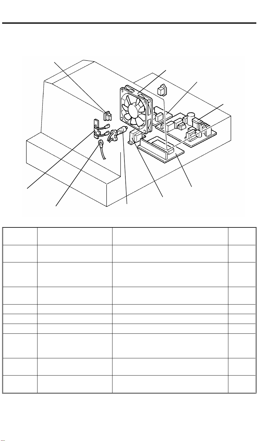
2. ELECTRICAL COMPONENT LAYOUT AND
DESCRIPTIONS
1
2
9
6
8
Symbol Name Function
PCB1
PCB2
PCB3
M1 Lamp Cooling Fan Blows air to the projector lamp section. 2
SW1 Projector Switch Provides power to the projector unit. 1
L1 Projector Lamp Applies light to the film for exposure. 7
TH1
TF1
TR1
Projector Lamp Regulator Supplies dc voltage to the projector lamp
Projector Control Board Controls the projector unit,
Noise Filter Board
(220–240V machine only)
Lamp Thermistor Detects the temperature around the
Lamp Thermofuse Opens the projector lamp circuit if the
Transformer Steps down the wall voltage to 17 ∼ 18 V
7
and lamp cooling fan.
communicating with the copier main
board.
Removes electrical noise.
projector lamp to control the lamp
cooling fan.
projector lamp section overheats.
ac.
4
Index
No.
4
5
3
8
9
6
2
Page 4
[I]
[E]
28 December 1993 SECTIONAL DESCRIPTIONS
3. SECTIONAL DESCRIPTIONS
3.1 OVERVIEW
[H]
[G]
[J]
[K]
This film projector unit allows making copies from the following kinds of films:
35 mm positive slides (both mount films and glass mount films)
35 mm negative or positive strip films
Positive or negative films of wide size
(60 x 45 / 60 x 60 / 60 x 70 / 60 x 80 / 60 x 90 mm / 4" x 5" /
maximum size of 140 x 210 mm or 5.5" x 8.2")
[C]
[A]
[B]
[D]
[F]
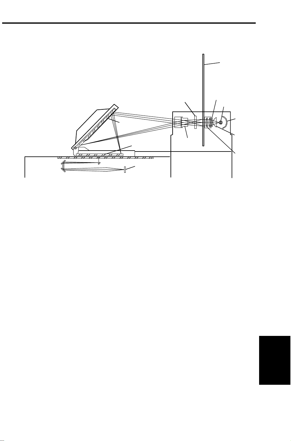
The light from the projector lamp [A] is reflected by the reflector [B] and
reaches the film (35 mm) in the film/slide holder [C] through the non-spherical
lens [D], heat filter [E], and condenser lenses [F]. The projected film image
reaches the mirror [G] through the correction filter (positive or negative) [H]
and projection lens [I]. Then the mirror reflects the image to the exposure
glass through the Fresnel lens [J]. The first scanner moves under the
exposure glass to read the projected film image and the light of the image is
converted to R/G/B electrical signals by the CCD [K].
The projected image on the exposure glass is enlarged about 6 times the 35
mm film’s image.
In the case of wide size films, the first scanner reads the film placed on the
exposure glass directly using the light from the projector lamp.
The lamp cooling fan turns on and off according to the temperature of the
projector lamp section detected by the lamp thermistor. It turns on at around
45°C and turns off at around 44°C.
Unit
Film Projector
3
Page 5
SECTIONAL DESCRIPTIONS 28 December 1993
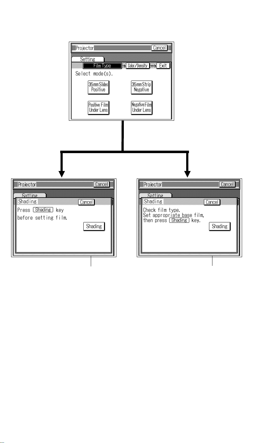
3.2 SHADING
[35 mm Slide Positive] or
[Positive Film Under Lens] On
[35 mm Strip Negative] or
[Negative Film Under Lens] On
[A][A]
When the projector unit is selected, shading should be done after selecting
the type of films. The shading should be done with a base film and the
N-correction filter for the negative films and with the P-correction filter for the
positive films.
The N-correction filter corrects color of the projected light. The P-correction
filter corrects the light intensity of the projected light so that it becomes similar
to that for the negative films.
When "Shading" [A] on the touch panel display is pressed, the first scanner
moves and stops under the mirror unit. Then AGC (Auto Gain Control) for the
light intensity from the projector lamp is performed. Shading for black and
white levels is also performed after the AGC.
This "Shading" should be performed whenever the type of film is changed or
the mirror unit is moved.
4
Page 6

[A]
28 December 1993 SECTIONAL DESCRIPTIONS
3.3 MIRROR UNIT
[C]
[B]
[A]
[F]
[C]
[B]
Subscan
direction
Main scan
direction
[D]
[E]
[F]
The film image projected through the projection lens [A] is reflected to the
Fresnel lens [B] by the mirror [C].
The Fresnel lens consists of two components, a circle pitch Fresnel lens [D]
and a parallel pitch Fresnel lens [E]. The circle pitch Fresnel lens changes
the spreading light to the parallel light. The parallel Fresnel lens collects the
light from the circle pitch Fresnel lens in the main scan direction so that all
the light reaches the color CCD lens [F].
The use of these two types of Fresnel lens makes the most of the light
intensity from the projector lamp.
Unit
Film Projector
5
Page 7

INSTALLATION 28 December 1993
4. INSTALLATION
4.1 ACCESSORY CHECK
Make sure that each accessory listed in the following table is in the box. Also
check the condition of each item.
1. Mirror Unit...............................................................................1
2. Power Cord............................................................................. 1
3. Optical Fiber Cable.................................................................1
4. Film Strip Holder.....................................................................1
5. Slide Holder............................................................................1
6. Glass Mount Holder................................................................1
7. Base Film (FUJI, KODAK, AGFA)..........................................3
8. Slide Mount............................................................................. 1
9. Correction Filter (P, N)............................................................ 2
10. Blower Brush.......................................................................... 1
11. Projection Lamp......................................................................1
12. Film Position Sheet.................................................................2
13. Positioning Pin........................................................................2
14. Spacer ....................................................................................4
15. Philips Pan Head Screw - M4 x 8...........................................2
16. Philips Pan Head Screw - M4 x 12......................................... 4
17. Installation Procedure.............................................................1
18. New Equipment Condition Report1 (-17/-27 only)..................1
19. Envelope for NECR (-17 only)................................................ 1
6
Page 8

[B]
28 December 1993 INSTALLATION
4.2 INSTALLATION PROCEDURE
[C]
[A]
[E]
[D]
NOTE: Holder (A702) must be installed before starting the following
procedure.
1. Remove the lower cover [A] from the holder bracket (2 screws).
2. Remove the cover plate [B] from the holder.
3. Install two positioning pins [C] on the holder bracket as shown (2 screws M4 x 8) and reinstall the lower cover.
4. Set four spacers [D] at the four corners on the hollow surface of the
holder.
5. Place the projector unit [E] on the holder by aligning the holes of the
projector base plate with the positioning pins.
Unit
Film Projector
7
Page 9

INSTALLATION 28 December 1993
[A]
[B]
[C]
[D]
[G]
[H]
[F]
[E]
6. Remove two rubber caps [A] and the rear cover [B] (4 screws).
7. Remove the shield plate [C] (2 screws).
8. Open the front cover and remove the front cover assembly [D] (2 screws).
9. Lower the lens cover [E] and loosen the screws for the lens cover shaft
stoppers [F].
10. Remove the lens cover.
11. Remove the lamp cover [G] (1 screw) and the top cover [H] (2 screws).
8
Page 10

28 December 1993 INSTALLATION
[B]
[A]
[E]
[D]
[F]
[C]
12. Fix the projector unit on the holder with 4 screws (M4 x 12).
13. Open the reflector cover [A], set the projection lamp [B] on the socket,
then close the reflector cover.
NOTE: The projection lamp should be inserted horizontally until it stops.
14. Remove the rubber block [C] from the optical fiber connector on the
copier.
15. Set the optical fiber cable [D] between the projector control board (CN6)
and the copier through the rubber bushing [E] as shown.
16. Set the power cord [F] to the power inlet and plug it in the wall outlet.
Unit
Film Projector
9
Page 11

[M]
[G]
[F]
INSTALLATION 28 December 1993
[D]
[B]
[J]
[H]
[A]
[E]
[C]
[K]
17. Replace the lens cover [A] on the projector unit and lower it on the
exposure glass.
NOTE: It is unnecessary to fix the lens cover shaft stoppers [B].
[I]
[L]
18. Place the film position sheet [C] on the exposure glass, aligning it at the
left rear corner.
19. Set the mirror unit [D] on the exposure glass by aligning the holes with
the positioning pins [E] of the lens cover.
20. Open the mirror unit and set the fresnel lens [F] at the lower position.
21. Set the slide mount (the empty one) [G] to the glass mount holder [H].
22. Insert the glass mount holder to the holder slot and position the slide
mount in front of the lenses by pressing and releasing the holder lever [I].
23. Turn on the test switch [J] on the projector control board and turn on the
projector main switch [K] so that the projection lamp turns on.
CAUTION: The lamp housing and reflector [L] will become very hot.
The lamp cooling fan [M] will start turning suddenly when
the lamp housing temperature becomes high. Keep hands
away from those components to avoid any injury.
10
Page 12

[C]
[D]
28 December 1993 INSTALLATION
[E]
[B]
[A]
24. Loosen the fixing screws [A] for the optical base plate.
25. While pressing down on the optical base plate, adjust the position of the
projected light by turning the adjusting dial [B] so that the position
becomes at the center of the fresnel lens.
NOTE: Use the mirror to look at the projected light on the fresnel lens.
Use the frames of the film position sheet as a reference. The side
to side position may be adjusted little by repositioning the
projector unit on the holder.
26. Tighten the fixing screws for the optical base plate.
27. Turn off the projector main switch and the test switch.
28. Reinstall the shield plate.
29. Remove the slide holder, the mirror unit, the lens cover, and the film
position sheet.
30. Reinstall the top cover [C].
NOTE: Install the top cover from the lens side. The focusing lever [D]
should be properly positioned. Be careful not to bend the holder
lever arm [E].
Unit
Film Projector
31. Reinstall the lens cover and other covers.
11
Page 13

INSTALLATION 28 December 1993
[B]
[A]
[C]
[C]
[D]
32. Adjust the angle [A] of the mirror unit as follows:
1) Turn on the copier main switch and wait for the ready condition.
2) Open the lens cover and set the mirror unit.
3) Set the correction filter [B] for positive films to the filter slot.
4) Turn on the projector main switch and press the option key.
5) Perform shading in positive 35 mm slides mode.
6) Set one of the orange base film in the slide holder and position it in the
projector unit.
7) Make a copy of the orange film.
8) Check if the orange image is even or not. If the image is uneven,
adjust the mirror angle as follows:
8-1) When the leading part is dark [C].
a) Move the front and rear arm guides [D] to the left so that the
mirror angle is increased (2 screws each).
NOTE:Position the front and rear arm guides evenly by using
the ruler decals.
b) Make a copy of the orange film.
c) Repeat a) and b) until the orange image becomes even.
12
Page 14

[A]
28 December 1993 INSTALLATION
[B]
8-2) When the trailing part is dark [A].
a) Move the front and rear arm guides [B] to the right so that the
mirror angle is reduced (2 screws each).
NOTE: Position the front and rear arm guides evenly by using
the ruler decals.
b) Make a copy of the orange film.
c) Repeat a) and b) until the orange image becomes even.
33. Check copy images from positive or negative films.
Unit
Film Projector
13
 Loading...