


INSTALLATION / OPERATION / MAINTENANCE
Applies to: Model VPT 120V 60Hz
Gas-Fired, Tubular, Radiant,
Low-Intensity Infrared Heater
Model VPT
High/Low Burner/Control Box
with 20 - 70 ft Tube/Reflector Length
|
|
Part No. 270684 |
Doc No 700106 (06-15), Page |
||

Introduction.
Welcome to the new range of powered HiLo infra-red heaters. Local regulations may vary and it is the installer’s responsibility to ensure that such regulations are satisfied.
All installation, assembly, commissioning and service procedures must be carried out by suitable qualified competent persons and conform with local building codes, or in the absence of local codes, with the National Fuel Gas Code ANSI Z223.1/NFPA 54 or the National Gas and Propane Installation Code CSA B149.1.
When assembling, installing, commissioning
and servicing is undertaken on radiant tube heaters specified in these instructions, due care and attention is required to ensure that working at height regulations are adhered to
 PLEASE READ this document prior to
  installation to familiarize yourself with the components and tools you require at the various
stages of assembly.
All Dimensions shown are in inches unless otherwise stated.
The manufacturer reserves the right to alter specifications without prior notice.
Document Index.
1 |
Installation Requirements |
3 |
Start Up Instructions |
||
|
1.1 |
Health & Safety |
|||
|
1.2 |
Heater Suspension |
|
3.1 |
Tools Required |
|
1.3 |
Clearance to Combustibles |
|
3.2 |
Start up procedure |
|
1.4 |
Gas Connection & Supply Details |
4 |
Servicing Instructions |
|
|
1.5 |
Electrical Connections |
|
4.1 |
Tools Required |
|
1.6 |
Ventilation Requirements |
|
4.2 |
Burner Description |
|
|
1.6.1 Unvented Units |
|
4.3 |
Burner Removal |
|
|
1.6.2 Vertical Venting |
|
4.4 |
Burner Gas Injector Servicing |
|
|
1.6.3 Horizontal Venting |
|
4.5 |
Burner Head and Electrode Servicing |
|
1.7 |
Fresh Air Intake |
|
4.6 |
Combustion Fan Assembly |
2 |
1.8 |
Technical Details |
|
4.7 |
Emitter Tube Servicing |
Assembly Instructions |
|
4.8 |
Reflector Servicing |
||
|
2.1 |
Tools Required |
|
4.9 |
Cleaning of Vent |
|
2.2 |
Assembly Notes |
|
4.10 Re-commissioning after Service |
|
|
|
2.2.1 Emitter tubes |
5 |
Troubleshooting Guide |
|
|
|
2.2.2 Turbulator Strips and Burner Inserts |
6 |
Replacing Parts |
|
|
|
2.2.3 Brackets |
|
6.1 |
Burner Controller Replacement |
|
|
2.2.4 Couplers |
|
6.2 |
Air Pressure Switch Replacement |
|
|
2.2.5 Reflectors |
|
6.3 |
Gas Valve Replacement |
|
|
2.2.6 End Caps (optional) |
7 User and Operating Instructions |
||
|
|
2.2.7 Bends (where required) |
|
7.1 |
To Start Heater |
|
|
2.2.8 Burner/Fan Assembly |
|
||
|
|
|
7.2 |
To Switch Off Heater |
|
|
|
2.2.9 Detailed Assembly Drawings |
|
||
|
|
|
7.3 |
Servicing |
|
|
|
|
|
||
1.Installation Requirements.
1.1Health and Safety
A.Heater is intended for heating non-residential indoor spaces and should only be installed where flammable gases or vapors are not present.
B.Heaters can be suspended horizontally or at any angle along the axis of the tubes but can only be rotated about the burner head 0 to 55°. See section 1.3 for clearance dimensions.
Doc No 700106 (06-15), Page 2
C.The installation must conform with local building codes or, in the absence of local codes, with the National Fuel Gas Code, ANSI Z223.1/NFPA 54 or the Natural Gas and Propane Installation Code, CSA B149.1.
D.The unit shall be electrically grounded in accordance with National Electric Code ANSI/NFPA 70 and Canadian Electrical Code CSA C22.1.
E.The heater may be installed in aircraft hangars in accordance with the Standard for
Aircraft Hangars, ANSI/NFPA 409 and in
automotive garages when installed in accordance with the Standard for Parking Structures, ANSI/NFPA 88A, or the Standard for Repair Garages, ANSI/NFPA 88B, or the Canadian Natural Gas and Propane Installation Code, CSA B149.1, and are so marked.
Ensure that minimum clearances will be maintained to vehicles parked below the heater.
F.The standard heaters are approved for installations between 0 - 2000ft (0 - 610m) above sea level for the US and 0 - 4500 ft (1370m) above sea level for Canada. Conversion kits are available for installations above these heights in the USA.
G.Massachusetts Requirement: If the heater is being installed in the Commonwealth of Massachusetts, this unit must be installed by a licensed plumber or licenced gas fitter.
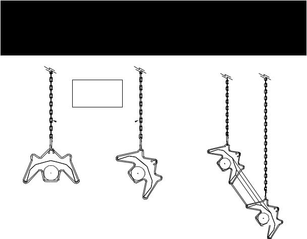
1.2Heater Suspension
Attachment to the heater support lugs should be made by D shackle. The hanging attachments to overhead steelwork etc. have
to be designed and produced in accordance with sound engineering practices. They must be adequately fixed and designed to carry the whole weight of the heater. In the event of suitable roof steelwork being unavailable, additional steelwork should be fitted to enable vertical hangers to be used for suspending the heaters.
These methods are illustrated in Figure 1. If there are any doubts as to the strength or suitability of roof steelwork to which heaters are to be suspended, please refer to a Consultant, Architect or owner of the building.
It is recommended that the heater is raised to its final position once the assembly of the emitter tube/bracket/reflector has been completed. Longer tube assemblies may be raised in more than one sub-assembly with final emitter tube connection made in the air.
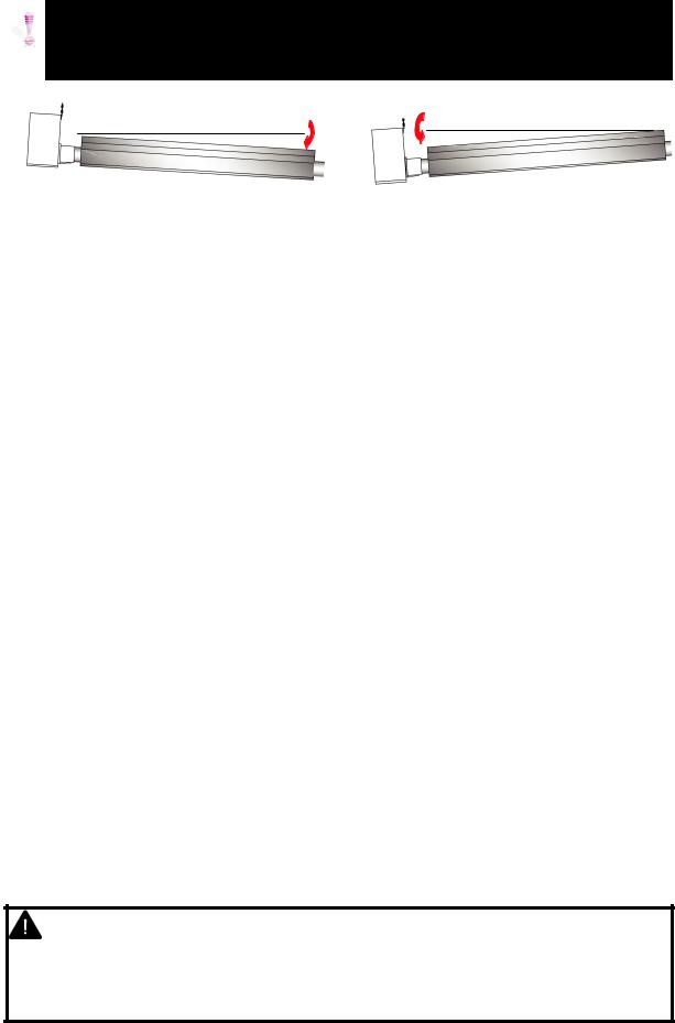
Ensure that the installer uses the burner roof support mounting bracket when suspending the heater. This is situated on the front of the burner. When packed the bracket is reversed and must be turned to its correct state for mounting. (ref page 15)
WARNING:
If not installed, operated and maintained in accordance with the manufacturer’s instructions, this product could expose you to substances in fuel or from fuel combustion which are known to the state of California to cause cancer, birth defects or other reproductive harm.
U TUBE VARIANTS
NOTE.
'S' HOOKS ARE TO BE CLOSED UP AFTER ASSEMBLY
 SUITABLE CHAIN
WORKING LOAD
LIMIT 100LB
EXHAUST
END
CHAIN |
55° SUSPENSION |
Figure 1. Recommended Methods of Heater Suspension. BURNER
END
Doc No 700106 (06-15), Page 3
ON VENTED HEATERS, THE HEATER SHOULD SLOPE DOWNWARDS AWAY FROM THE BURNER AND ON UNVENTED HEATERS SHOULD SLOPE DOWNWARDS TOWARDS BURNER BY APPROX. ½” FOR HORIZONTAL INSTALLATIONS AS SHOWN BELOW (DIAGRAMS EXAGGERATED FOR CLARITY)
|
1/2” |
1/2” |
|
|
|
VENTED |
|
UNVENTED |
1.3Clearance to Combustibles.
Minimum clearance to combustibles are shown in Table 1 below.
IMPORTANT:
The stated clearance to combustibles represents a surface temperature of 90°F (50°C) above room temperature. Building material with a low heat tolerance (such as plastics, vinyl siding, canvas, tri-ply, etc.) may be subject to degradation at lower temperatures. It is the installer’s responsibility to assure that adjacent materials are protected from degradation.
Table 1 |
Clearance to Combustibles, inches (cm) |
|
|
|
|
|
|||||
|
|
|
|
|
|
|
|
|
|
|
|
MODEL |
A |
A1 / A2 |
B |
B1 |
C1 |
C2 |
C3 |
D1 |
D2 |
E |
|
|
|
|
|
|
|
|
|
|
|
|
|
60 |
74 |
|
29 |
41 |
20 (51) / |
8 |
22 |
8 |
12 |
12 |
|
(188) |
|
(74) |
(105) |
10* (26)* |
(21) |
(56) |
(21) |
(31) |
(31) |
||
|
|
||||||||||
|
|
|
|
|
|
|
|
|
|
|
|
80 |
74 |
|
29 |
41 |
20 (51) / |
8 |
22 |
8 |
12 |
12 |
|
(188) |
|
(74) |
(105) |
10* (26)* |
(21) |
(56) |
(21) |
(31) |
(31) |
||
|
15° = 72 (183) |
||||||||||
|
|
|
|
|
|
|
|
|
|
||
|
74 |
25° = 68 (173) |
32 |
41 |
20 (51) / |
8 |
22 |
8 |
16 |
12 |
|
100 |
35° = 61 (155) |
||||||||||
(188) |
(82) |
(105) |
10* (26)* |
(21) |
(56) |
(21) |
(41) |
(31) |
|||
|
45° = 53 (135) |
||||||||||
|
|
|
|
|
|
|
|
|
|
||
125 |
74 |
55° = 43 (110) |
39 |
47 |
20 (51) / |
8 |
22 |
20 |
18 |
12 |
|
|
|||||||||||
(188) |
|
(99) |
(120) |
10* (26)* |
(21) |
(56) |
(51) |
(46) |
(31) |
||
|
|
||||||||||
|
|
|
|
|
|
|
|
|
|
|
|
150 |
74 |
|
39 |
48 |
20 (51) / |
8 |
22 |
20 |
18 |
12 |
|
(188) |
|
(99) |
(122) |
10* (26)* |
(21) |
(56) |
(51) |
(46) |
(31) |
||
|
|
||||||||||
|
|
|
|
|
|
|
|
|
|
|
|
170 |
86 |
15° = 82 (209) |
48 |
48 |
20 (51) / |
11 |
22 |
20 |
20 |
12 |
|
(219) |
25° = 78 (199) |
(122) |
(122) |
10* (26)* |
(28) |
(56) |
(51) |
(51) |
(31) |
||
|
|||||||||||
|
|
35° = 71 (181) |
|
|
|
|
|
|
|
|
|
|
|
|
|
|
|
|
|
|
|
||
200 |
86 |
45° = 61 (155) |
48 |
48 |
20 (51) / |
11 |
22 |
20 |
20 |
12 |
|
(219) |
55° = 50 (127) |
(122) |
(122) |
10* (26)* |
(28) |
(56) |
(51) |
(51) |
(31) |
||
|
|||||||||||
|
|
|
|
|
|
|
|
|
|
|
|
* distance with end caps fitted.
WARNING: Minimum clearance from the heater must be maintained from vehicles parked below heater. In all situations, clearances to combustibles must be
maintained. Signs should be posted in storage areas to specify maximum stacking height to maintain required clearance to combustibles. Such signs must either be posted adjacent to the heater thermostats or in the absence of such thermostats in a conspicuous location.
Refer to mounting clearance tables.
Doc No 700106 (06-15), Page 4

Figure 2 Clearance to Combustibles (Standard indoor reflectors)..
 The minimum clearances to combustible materials are given in Table 1 These minimum
 distances MUST be adhered to at all times. Adequate clearance MUST be provided around air openings into the combustion chamber and there MUST be suitable clearance for accessibility and
for combustion / ventilating air supplies.
A2 |
to55°. |
Angled view. |
|
0° |
|
|
A1 |
|
|
|
|
|
|
|
|
|
|
|
|
|
|
|
|
|
|
|
|
|
|
D2 |
|
|
|
|
Return end on U tube heater |
|
||||||||
|
|
|
|
|
|
|
|
|
|
|
|
|
|
|
|
|
|
|
|
|
|
|
|||||||||||||
|
|
|
|
|
|
|
|
|
|
|
|
|
|
|
|
|
|
|
|
|
|
|
|
|
|
|
|||||||||
|
|
|
|
|
|
|
|
|
|
|
|
|
|
|
|
|
|
|
|
|
|
|
|
|
|
|
|
|
|
|
|
|
|
|
|
|
|
|
|
|
|
|
|
|
|
|
|
|
|
|
|
|
|
|
|
|
|
|
|
|
|
|
|
|
|
|
|
|
|
|
|
|
|
|
|
|
|
|
|
|
|
|
|
|
|
|
|
|
|
|
|
|
|
|
|
|
|
|
|
|
|
|
|
|
|
|
|
|
|
|
|
|
|
|
|
|
|
|
|
|
|
|
|
|
|
|
|
|
|
|
|
|
|
|
|
|
|
|
|
|
|
|
|
|
|
|
|
|
|
|
|
|
|
|
|
|
|
|
|
|
|
|
|
|
|
|
|
|
|
|
|
|
|
|
|
|
|
|
|
|
|
|
|
|
|
|
|
|
|
|
|
|
|
|
|
|
|
|
|
|
|
|
|
|
|
|
|
|
|
|
|
|
|
|
|
|
|
|
|
|
|
|
|
|
|
|
|
|
|
|
|
|
|
|
|
|
|
|
|
|
|
|
|
|
|
|
|
|
|
|
|
|
|
|
|
|
|
|
|
|
|
|
|
|
|
|
|
|
|
|
|
|
|
|
|
|
|
|
|
|
|
|
|
|
|
|
|
|
|
|
|
|
|
|
|
|
|
|
|
|
|
|
|
|
|
|
|
|
|
|
|
|
|
|
|
|
|
|
|
|
|
|
|
WARNING! |
therethatEnsureis adequate |
theinprovisionbuilding for andcombustionventilation air supply. |
mustInstallationmeet minimum |
requirementsand applicable codes. |
|
Outlet end. |
D1 |
Side |
unvented |
Above |
Reflector unvented |
|
|
|
|
|
|
|
|
|
|
|
|
C3 |
|
|
|
|
|
|
|
|
|
End |
unvented |
|
outletAbove |
|
|
|
|
|
|
|
|
|
B1 |
|
|
|
|
|
|
B |
|
|
Below |
heater |
|
|
|
C2 |
Burner end. |
|
|
A |
|
|
|
|
B Side vented |
Endview. |
Above Burner |
Above Burner |
E |
Service distance |
|
|
C1 |
C1 |
|
|
Doc No 700106 (06-15), Page 5

1.4Gas Connection and Supply
WARNING: Before installation, check that the local distribution conditions, nature of gas and pressure, and adjustment
of the appliance are compatible.
The gas connection on the heater is ½” N.P.T internal thread.
Injector sizes and manifold pressure for the burners are shown in the table 3. The gas supply piping and connections must be installed so that the minimum pressure stated is achieved.
A gas shut off valve and union should be fitted in the gas supply line close to the heater and a ⅛” N.P.T plugged tapping, accessible for test gauge connection, provided immediately upstream of the appliance gas inlet.
It is essential to provide some flexibility in the final gas connection by use of an approved flexible gas connector. (See Fig 4.)
 Take care when making a gas connection
  to the heater not to apply excessive turning
force to the internal controls.
Care must be taken to observe the pipe bend diameter of 12” (30cm) and pipe displacement distance of 3” (7.62cm).
 The correct installation as shown will allow
  for approx 4” of movement due to
expansion.
* Connector must be certified for use on a radiant tube type infrared heater and must comply with Standard for Connectors for Gas Appliances, ANSI Z21.24/CSA 6.10 or with the Standard for Elastomeric Composite Hose and Hose Couplings for Conducting Propane and Natural Gas, CAN/CGA 8.1.
For heaters up to 150,000Btu/h, ½” ID x 24” long
For heaters 150,000Btu/h and above, ¾” ID x 36” long NOTE: For Canada all heaters MUST use a hose 36” long (See Table 3)
Figure 3. Correct orientation of Ball Valve
Gas Flow
Gas Flow
Figure 4. Correct Installation of Flexible
Gas Connection
Table 3 |
|
|
|
|
|
|
HOSE SIZE |
|
USA |
|
CANADA |
|
|
|
|||
|
|
|
|
|
|
|
3/4” |
|
CE4 |
|
CONTACT |
|
|
|
FACTORY |
||
|
|
|
|
|
|
|
|
|
|
|
|
WARNING: FIRE OR EXPLOSION HAZARD - It is essential to provide some flexibility in the final gas line connection by use of an approved flexible connector as shown in the drawings. Expansion of the radiant pipe occurs with each firing cycle causing the burner to move with respect to the gas line. This can result in a gas leak producing an unsafe
condition.
Doc No 700106 (06-15), Page 6

CONNECTOR MUST BE INSTALLED IN A “U” CONFIGURATION. FOR HEATERS UP TO 150,000 BTU/H, A 24” LONG CONNECTOR OF AT LEAST ½” ID MUST BE USED. FOR HEATERS ABOVE 150,000 BTU/H, A 36” LONG CONNECTOR OF AT LEAST ¾” NOMINAL ID MUST BE USED.
Table 4 Gas Supply Pressures
Gas Type |
Natural Gas |
LP/Propane Gas |
|
|
|
Min Required Gas Pressure (in W.C) |
7.0 |
11.0 |
|
|
|
Max Supply Pressure (in W.C) |
14.0 |
14.0 |
|
|
|
Gas Supply |
Connection ½” N.P.T thread |
|
|
|
|
1.5Electrical Connections
WARNING: Before making electrical connections, switch OFF the main electrical disconnect. There may be more than one disconnect switch. Lock out and tag switch with a suitable warning label. Electrical shock can cause
personal injury or death.
This appliance must be electrically grounded
Supply 120V 60Hz single phase. Standard heater 0.16HP. Current rating (inductive):
1.8 amp max (models 60 - 150)
1.0 amp max (models 170 & 200) Fuse: external 3 amp.
Important: All electrical work should be done by a qualified electrician in strict accordance with the National Electrical Code ANSI/NFPA 70 or Canadian Codes CSA C22.1.
The electrical supply to the heater is by three wires: hot (Live), neutral and ground connections.
Install in accordance with all state & local codes.
Where alternative manufacturers controls are used, please refer to their instructions for their installation details.
Figure 5. External Wiring Schematic |
24V AC 2-Stage |
|
|
|
Thermostat (Ext.) |
|
Burner 1 |
|
R C W1 W2 |
|
|
R |
BK |
|
|
|
BL |
|
||
24V AC |
C |
|
||
R |
|
|||
Terminals |
W1 |
|
||
|
W2 |
O |
|
|
|
|
|
||
|
F1 |
|
|
|
(120V AC Fan |
F2 |
|
|
|
|
|
|
||
Terminals) |
E |
|
KEY: |
|
|
|
|
||
|
N |
|
BK-BLACK |
|
BK |
L |
|
BL-BLUE |
|
120V AC |
R-RED |
|||
|
|
|||
G |
E |
O-ORANGE |
||
Supply |
||||
W |
|
G-GREEN |
||
N |
|
W-WHITE |
Notes:
Use 18/4 class 2 thermostat cable between heater and thermostat.
Max. length @ 18 Awg (0.8mm²) = 100ft.
Only one burner can operate from one thermostat as supplied.
When servicing heaters ensure the electricity supply is isolated from the mains supply.
120V AC supply is still present at each burner when the thermostat is switched off.
Doc No 700106 (06-15), Page 7
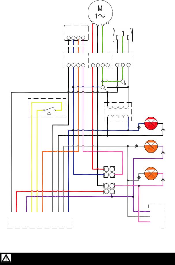
Figure 6a. Internal Burner Wiring Diagram.
24V Two stage |
|
|
|
|
E |
|||
Thermostat |
|
|
|
L |
N |
|||
R |
C |
W1 |
W2 |
|
|
|
|
|
BR |
BL |
O |
K |
R |
BK G W |
BK |
G |
W |
24V AC Stat |
120V AC Fan |
120V AC |
||||||
Terminals |
|
Terminals |
|
Supply |
||||
R |
C |
W1 |
W2 |
F1 |
F2 |
E |
N |
L |
E |
N |
BR |
BL |
O |
K |
R |
BK |
G |
W |
BK |
G |
W |
|
|
|
|
|
|
|
|
|
E |
|
|
|
|
|
|
|
E |
|
|
|
|
|
BK |
W |
Y |
Y |
|
|
|
120V/24VAC 60Hz |
Pressure Switch |
|
|
|
BR |
Transformer |
High Fire
Relay
R |
12 |
|
22 |
||
BL |
NC |
|
A1 |
||
A2 |
||
|
COIL |
24V AC RELAY
BK |
14 |
|
24 |
||
R |
NO |
|
11 |
||
21 |
||
|
COM |
|
BK |
|
R |
P |
Y |
Y |
O |
|
BR |
BR |
|
GR |
|
BL |
|||||||||||||||||||
|
|
|
|
|
|
|
|
|
|
|
|
|
|
|
|
|
|
|
|
|
|
|
|
|
|
|
|
|
|
|
|
|
|
|
|
|
|
|
|
|
|
|
|
|
|
|
|
|
|
|
|
|
|
|
|
|
|
|
|
|
|
|
|
||||
|
|
L1 |
|
|
IND |
|
|
MV |
|
|
PS1 |
|
|
PS0 |
|
W1 |
|
|
R |
|
X |
|
|
C |
|
|
COM |
|
|
||||
|
|
|
|
|
|
|
|
|
|
|
|
|
|||||||||||||||||||||
|
|
|
|
|
|
|
|
|
|
|
|
|
|
|
|
|
|
|
|
|
|
|
|
|
|
|
|
|
|
|
|
|
|
Gas Control
KEY:
BL - BLUE
BK - BLACK
BR - BROWN
GR - GREY
G - GREEN
K - PINK
R - RED
W - WHITE
Y - YELLOW
O - ORANGE
P - PURPLE
Power ON (red)
BL 
 BR
BR
GR 
 P
P
Low Fire
(amber)
GR 
 K
K
High Fire
P |
|
|
|
|
Valve |
|
|
|
C |
||||
|
|
|
M |
|
|
|
GR |
|
|
|
|
Gas |
|
|
|
|
|
|||
K |
|
|
|
|
||
|
|
|
HI |
|
|
|
|
|
|
|
|
|
|
|
|
|
|
|
|
|
NOTES:-
Power On light is permanently illuminated when 120V / 60 Hz AC external supply is connected to burner. Additional wiring is required to install an optional extra thermostat and / or time clock.
Wire specification:- 18 AWG (1.0mm²), Tri-rated, 105°C
If any of the original wire as supplied with the appliance must be replaced, it must be replaced with wiring material having a temperature rating of at least 220°F/105°C
Doc No 700106 (06-15), Page 8
1.5.1 Multiple burner configurations (Master & Slave) via Optional Relay .
Refer to figure 6b and 6d.
Multiple VPT burners can be controlled via one main burner. In this scenario the main burner is knows as the ‘Master’ and any additional burners are known as ‘Slaves’.
The external two stage thermostat is connected to the Master burner and powered via the inbuilt transformer. The total burner load for the Master is 20VA. Each additional ‘Slave’ burner is 1.6VA
The Thermostat chosen to control the multiple heaters must not have a power requirement exceeding the spare capacity as shown in the examples below:
CONFIGURATION |
TOTAL BURNER LOAD |
SPARE FOR THERMOSTAT |
|
|
|
|
|
Master PLUS 1 |
Slave |
21.6VA |
18.4VA |
Master PLUS 3 |
Slaves |
24.8VA |
15.2VA |
Master PLUS 5 |
Slaves |
28.0VA |
12.0VA |
Master PLUS 7 |
Slaves |
31.3VA |
8.8VA |
|
|
|
|
Figure 6b. Wiring schematic. Multiple Burners Master and Slave.
GND 
 L2
L2 


 L1 (HOT)

120V 60Hz 1 Ph |
|
|
|
|
|
|
|
|
|
|
|
|
Supply circuit |
|
|
|
|
|
|
|
|
|
|
|
|
|
L N E |
|
L N E |
|
L N E |
|
L N E |
|||||
|
|
|
|
|
|
|||||||
R |
|
R |
MASTER |
|
SLAVE |
|
SLAVE |
|
SLAVE |
|||
C |
|
C |
BURNER |
|
BURNER |
|
BURNER |
|
BURNER |
|||
W1 |
|
W1 |
|
|
|
|||||||
W2 |
|
W2 |
|
|
W1 |
W2 |
|
W1 |
W2 |
|
W1 |
W2 |
THERMOSTAT |
|
|
|
|
|
|
||||||
|
|
|
|
|
|
|
|
|
|
|
|
|
|
|
|
|
|
|
|
|
|
|
|
|
|
24VAC 60Hz 1 Ph Hi/Lo circuit
1.5.2 Multiple burner configuration via independently powered two stage thermostats. Refer to figures 6c and 6d.
Note: If the thermostat has an independent power supply, all burners in the zone to be controlled MUST be Slave burners.
The maximum number of Slave burners per thermostat is dependent on the maximum power output of the thermostat selected.
Each ‘Slave’ burner is rated at 1.6VA 24VAC 60Hz.
The external two stage thermostat is powered via its own power supply and must output to each Slave burner - 24VAC for low fire to terminal W1 and 24VAC for hi fire to both terminals W1 and W2
Refer to thermostat manufactures literature for details.
Figure 6c. Wiring schematic. Multiple Burners via independently powered Relay.
GND
L2
L1 (HOT)
120V 60Hz 1 Ph |
|
|
|
|
|
|
|
|
|
|
|
|
|
Supply circuit |
|
|
|
|
|
|
|
|
|
|
|
|
|
|
|
L N E |
|
L N E |
|
L N E |
|
L N E |
|||||
|
|
|
|
|
|
|
|||||||
|
|
|
W1 |
SLAVE |
|
SLAVE |
|
SLAVE |
|
SLAVE |
|||
Low fire output |
|
|
|
|
|
||||||||
|
|
BURNER |
|
BURNER |
|
BURNER |
|
BURNER |
|||||
Hi fire output |
|
|
W2 |
|
|
|
|
|
|
|
|
|
|
THERMOSTAT |
|
|
|
|
|
W1 |
W2 |
|
W1 |
W2 |
|
W1 |
W2 |
|
|
24VAC 60Hz 1 Ph Hi/Lo circuit |
|
|
|
|
|
|
|
||||
Supply Circuit |
|
|
|
|
|
|
|
||||||
(by others) |
|
|
|
|
|
|
|
|
|
|
|
|
|
Doc No 700106 (06-15), Page 9
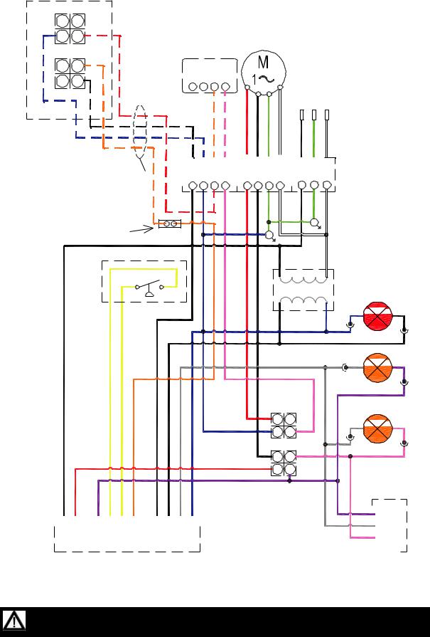
Figure 6d. Internal Slave Burner Wiring/External Schematic Diagram with Optional Relay.
22 |
12 |
OPTIONAL RELAY WIRING |
|
BL |
R |
|
|
A2 |
A1 |
|
|
|
COIL |
|
|
24V AC |
|
||
RELAY |
|
||
|
O |
24V Two stage |
|
24 |
14 |
||
|
NO |
Thermostat |
|
21 |
11 |
||
R C W1 W2 |
|||
|
COM |
||
|
|
||
BL |
BR |
O |
O |
K |
L E N
R |
BK |
G |
W |
BK |
G |
W |
Relay mini harness leads |
|
|
|
|
|
|
|
|
|
|
|
|
|
|
|
|
|
|
|
|
|
||
|
24V AC Stat |
|
120V AC Fan |
|
120V AC |
||||||||||||||||||
|
|
|
|||||||||||||||||||||
|
|
|
|
|
Terminals |
|
|
Terminals |
|
Supply |
|||||||||||||
R |
C |
W1 |
W2 |
F1 |
F2 |
E |
N |
L |
E |
N |
BR |
BL |
|
K |
R |
BK |
G |
W |
BK |
G |
W |
5A connector |
|
|
|
|
|
|
|
|
E |
|
|
|
|
|
|
E |
|
|
|
|
|
BK |
W |
Y |
Y |
|
|
|
120V/24VAC 60Hz |
Pressure Switch |
|
|
|
BR |
Transformer |
High Fire
Relay
R |
12 |
|
22 |
||
BL |
NC |
|
A1 |
||
A2 |
||
|
COIL |
24V AC RELAY
BK |
14 |
|
24 |
||
R |
NO |
|
11 |
||
21 |
||
|
COM |
|
BK |
|
R |
P |
Y |
Y |
O |
|
BR |
BR |
GR |
|
BL |
|||||||||||||||||||
|
|
|
|
|
|
|
|
|
|
|
|
|
|
|
|
|
|
|
|
|
|
|
|
|
|
|
|
|
|
|
|
|
|
|
|
|
|
|
|
|
|
|
|
|
|
|
|
|
|
|
|
|
|
|
|
|
|
|
|
|
|
||||
|
|
L1 |
|
|
IND |
|
|
MV |
|
|
PS1 |
|
|
PS0 |
|
W1 |
|
|
R |
|
X |
|
C |
|
|
COM |
|
|
||||
|
|
|
|
|
|
|
|
|
|
|
|
|||||||||||||||||||||
|
|
|
|
|
|
|
|
|
|
|
|
|
|
|
|
|
|
|
|
|
|
|
|
|
|
|
|
|
|
|
|
|
Gas Control
KEY:
BL - BLUE
BK - BLACK
BR - BROWN
GR - GREY
G - GREEN
K - PINK
R - RED
W - WHITE
Y - YELLOW
O - ORANGE
P - PURPLE
Power ON (red)
BL 
 BR
BR
GR 
 P
P
Low Fire
(amber)
GR 
 K
K
High Fire
P |
|
|
|
|
Valve |
|
|
|
C |
||||
|
|
|
M |
|
|
|
GR |
|
|
|
|
Gas |
|
K |
|
|
|
|
||
|
|
|
HI |
|
|
|
|
|
|
|
|
|
|
|
|
|
|
|
|
|
NOTES:-
Power On light is permanently illuminated when 120V / 60 Hz AC external supply is connected to burner. Additional wiring is required to install an optional extra thermostat and / or time clock.
Wire specification:- 18 AWG (1.0mm²), Tri-rated, 105°C
If any of the original wire as supplied with the appliance must be replaced, it must be replaced with wiring material having a temperature rating of at least 220°F/105°C
Doc No 700106 (06-15), Page 10
1.6 Vent Requirements and Details
1.6.1 Unvented units
Heaters may be installed unvented providing the governing building codes are met and consideration is properly given to possibilities of condensation on cold surfaces.
Installation shall meet the following requirements when unvented:
•Natural or mechanical means shall be provided to supply and exhaust at least 4 CFM per 1000 BTU per hour input of installed heaters.
•Combustion gases shall not impinge on combustible materials.
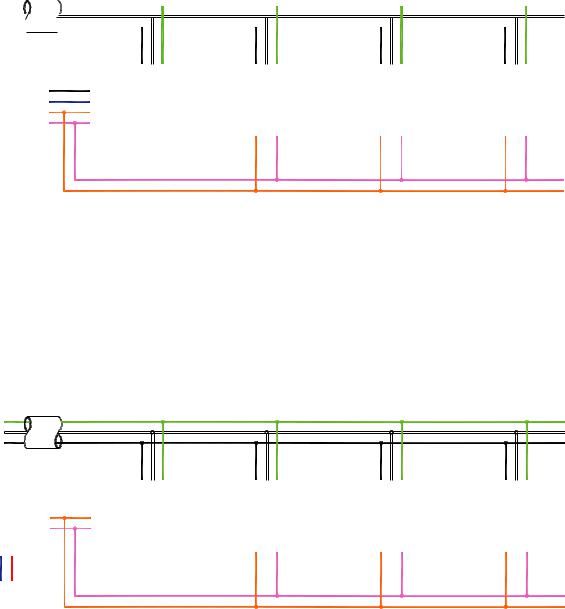
1.6.2 Vertical venting
The heater can be installed with a vertical vent.
All vent piping should be adequately supported from the building structure and terminated with an approved terminal. The maximum recommended vent length is 25ft (7.6m) with a maximum of two elbows. All connections should be properly sealed. refer fig 7a
1.6.3 Horizontal venting
Individual units can be vented horizontally through side walls. Recommended terminals are Part Numbers 111848 for 4” and 111850 for 6”.
Distances from adjacent public walkways, adjacent buildings, openable windows and building openings, consistent with the National Fuel Gas Code, ANSI Z223.1/NFPA 54 or the Natural Gas and Propane Installation Code, CSA B149.1.
The maximum recommended vent length is 25ft (7.6m) with a maximum of two 90° elbows. However runs up to 12ft (3.6m) can use 4” (101mm) vent pipe. Runs over 12ft (3.6m) should always use 6” (152mm) vent pipe.
An approved clearance thimble is required when the flue pipe passes through combustible materials. Follow the requirements of the thimble manufacturer.
Standard vent terminals must extend at least 6” (152mm) from the wall and at least
Doc No 700106 (06-15), Page 11
24” (609mm) from any combustible overhang. This protects the building material from degradation by the vent gases.
Vent joints should be sealed and secured according to the vent manufacturers instructions. Should condensation occur the vent should be shortened or insulated.
The terminal should be at least 3ft (0.91m) from any air intake to the building.
The vent terminal must be installed at a suitable height above the ground to prevent blockage by snow.
1.7Fresh Air Intake
Whenever the heater is installed in locations where airborne dust or other pollutants are present, a fresh air supply should be ducted to the burner.
If the heater is equipped with ducted combustion air, the vent terminal must be at least 3ft (0.91m) away from the air inlet and located higher than the inlet.
A fresh air duct of 4” (101mm) diameter should be installed from the fresh air to the air intake connection on the fan housing. A flexible jointing piece should be installed at the fan connection with hose clamps to facilitate expansion and contraction.
The maximum recommended length air duct is 25ft (7.6m) and the maximum number of elbows is two. The minimum length is 18” (456mm).
The location of the fresh air duct inlet must be where it will receive dust free clean air. An inlet cap with bird screen must be fitted at the inlet of the duct. If the duct inlet is located above the roof the underside of the inlet terminal must be at least 2ft (0.61m) above roof level (or above projected snow load) and at least 10” (254mm) above any projection on the roof within 7ft (2.1m) of the inlet. Intake pipe, fittings and sealant are not furnished by the manufacturer. Refer fig 7c & d.
Note the vent terminal must NOT be installed below the fresh air intake, and should have a minimum separation distance of 36” from the air intake.
Note The vent terminal should be installed so as to be in the same atmospheric pressure zone as the combustion air inlet of the appliance.

Figure 7.a Vertical Venting.
Approved clearance thimble is required when the flue pipe extends through combustible materials. Follow the requirements of the thimble and/or Category III vent pipe manufacturer.
Figure 7.b Horizontal Venting (plan view shown).
Approved clearance thimble is required when the flue pipe extends through combustible materials. Follow the requirements of the thimble and/or Category III vent pipe manufacturer.
Note The vent terminal should be installed so as
to be in the same atmospheric pressure zone as the combustion air inlet of the appliance.
Note the vent terminal must NOT be installed below the fresh air intake, and should have a minimum separation distance of 36” from the air intake.
Figure 7.c Fresh Air Ducted Intake.
Aluminum 4” (101mm) O.D. pipe.
Max length = 25’0” (7.62M) with 2 x 90° long radius bends.
Clamps
4” (101mm) O.D. flexible duct 

Burner 
Doc No 700106 (06-15), Page 12
1.8Technical Details - Table 5
|
No of Injectors |
|
|
|
1 |
|
|
|
||
|
|
|
|
|
|
|
|
|
|
|
|
Gas Connection |
|
|
|
|
½” N.P.T |
|
|
||
|
|
|
|
|
|
|
|
|
|
|
|
Electrical Supply |
|
|
|
120 volt 1 phase 60Hz |
|
||||
|
|
|
|
|
|
|
|
|
||
|
Vent size (in) |
|
|
4” or 6” (101mm or 152mm) |
|
|||||
|
|
|
|
|
|
|
|
|
||
Unitary Fan Motor Details |
|
|
120 volt 1 phase 60Hz |
|
||||||
|
|
|
|
|
|
|
|
|
||
|
Current Rating |
|
1.8A MAX (models 60 - 150); 1.0A MAX (models 170 & 200) |
|||||||
|
|
|
|
|
|
|
|
|
||
|
|
Ignition |
|
|
Electronic Program Start up with Spark Ignition |
|||||
|
|
|
|
|
|
|
|
|
|
|
|
|
|
|
|
|
|
|
|
|
|
|
|
Natural Gas |
LP Gas |
Min. Heater |
|
Max. Heater |
|
Min. Heater |
Max. Heater |
|
|
|
Length |
|
Length |
|
Length |
Length |
|||
MODEL |
|
|
|
|
|
|||||
High / Low |
High / Low |
S ft |
|
S ft |
|
U ft |
U ft |
|||
|
|
|
|
|||||||
|
|
|
|
|
|
|
|
|
|
|
60 |
|
60,000/48,000 |
60,000/48,000 |
20 |
|
40 |
|
20 |
40 |
|
80 |
|
80,000/60,000 |
80,000/60,000 |
30 |
|
40 |
|
40 |
40 |
|
100 |
|
100,000/75,000 |
100,000/75,000 |
30 |
|
40 |
|
40 |
40 |
|
125 |
|
123,500/95,000 |
125,000/95,000 |
30 |
|
50 |
|
40 |
40 |
|
150 |
|
150,000/100,000 |
150,000/100,000 |
40 |
|
60 |
|
40 |
60 |
|
170 |
|
169,000/125,000 |
169,000/125,000 |
50 |
|
70 |
|
60 |
60 |
|
200 |
|
200,000/160,000 |
N/A |
50 |
|
70 |
|
60 |
60 |
|
|
|
|
|
|
|
|
|
|
|
|
Appliances can be installed up to 10,000ft above sea level in the USA. Altitude conversion kits are available on request.
USA |
0- 2000 ft (0-610m) above sea level |
||||||
|
|
|
|
|
|
|
|
Size |
60 |
80 |
100 |
125 |
150 |
170 |
200 |
Gas |
|
|
Natural Gas |
|
|
||
Hi “WC |
3.9 |
3.5 |
4.5 |
4.3 |
4.0 |
3.3 |
4.0 |
|
|
|
|
|
|
|
|
Lo “WC |
2.6 |
2.3 |
3.0 |
2.7 |
2.1 |
1.9 |
2.5 |
|
|
|
|
|
|
|
|
|
|
|
|
|
|
|
|
USA |
0- 2000 ft (0-610m) above sea level |
||||||
|
|
|
|
|
|
|
|
Size |
60 |
80 |
100 |
125 |
150 |
170 |
200 |
Gas |
|
|
|
LP Gas |
|
|
|
Hi “WC |
5.5 |
5.2 |
8.0 |
7.6 |
7.0 |
6.1 |
N/A |
|
|
|
|
|
|
|
|
Lo “WC |
3.5 |
2.9 |
4.4 |
4.6 |
3.3 |
3.6 |
N/A |
|
|
|
|
|
|
|
|
CANADA |
0- 2000 ft (0-610m) above sea level |
||||||
|
|
|
|
|
|
|
|
Size |
60 |
80 |
100 |
125 |
150 |
170 |
200 |
Gas |
|
|
Natural Gas |
|
|
||
Hi “WC |
3.9 |
3.5 |
4.5 |
4.3 |
4.0 |
3.3 |
4.0 |
|
|
|
|
|
|
|
|
Lo “WC |
2.6 |
2.3 |
3.0 |
2.7 |
2.1 |
1.9 |
2.5 |
|
|
|
|
|
|
|
|
|
|
|
|
|
|
|
|
CANADA |
0- 2000 ft (0-610m) above sea level |
||||||
|
|
|
|
|
|
|
|
Size |
60 |
80 |
100 |
125 |
150 |
170 |
200 |
Gas |
|
|
|
LP Gas |
|
|
|
Hi “WC |
5.5 |
5.2 |
8.0 |
7.6 |
7.0 |
6.1 |
N/A |
|
|
|
|
|
|
|
|
Lo “WC |
3.5 |
2.9 |
4.4 |
4.6 |
3.3 |
3.6 |
N/A |
|
|
|
|
|
|
|
|
Doc No 700106 (06-15), Page 13
Technical Details continued
|
|
USA & CANADA |
|
|
|
|
|
Natural Gas 0- 2000 ft (0-610m) |
|
||||||||||||
|
|
|
|
|
|
|
|
|
|
|
|
|
|
|
|
|
|
|
|
|
|
|
|
|
Size |
|
|
|
|
60 |
|
80 |
|
|
100 |
|
125 |
|
150 |
170 |
|
200 |
|
|
Burner Orifice Plate Part No. |
|
269941 |
|
269942 |
|
269943 |
269944 |
1005513 |
269946 |
|
269946 |
|||||||||
|
Flame Plate Part No. |
|
|
|
|
|
|
|
|
|
N/A |
|
|
|
|
||||||
|
|
Fan Part No. |
|
|
|
|
|
|
270464 |
|
|
|
270467 |
||||||||
|
Fan Orifice Part No. |
|
269922 |
|
269925 |
|
269925 |
269930 |
269931 |
266935 |
|
269938 |
|||||||||
|
|
Injector Part No. |
|
270400 |
|
270402 |
|
270403 |
270405 |
270407 |
270409 |
|
270410 |
||||||||
|
Injector Carrier Part No. |
|
|
|
|
|
|
270375 |
|
|
|
270376 |
|||||||||
|
Pressure Switch Part No. |
|
|
|
|
|
|
270389 |
|
|
|
|
270390 |
||||||||
|
|
|
|
|
|
|
|
|
|
|
|
|
|
|
|
||||||
|
|
USA & CANADA |
|
|
|
|
|
|
LP Gas 0- 2000 ft (0-610m) |
|
|||||||||||
|
|
|
|
|
|
|
|
|
|
|
|
|
|
|
|
|
|
|
|
|
|
|
|
|
Size |
|
|
|
|
60 |
|
80 |
|
|
100 |
|
125 |
|
150 |
170 |
|
200 |
|
|
Burner Orifice Plate Part No. |
|
269948 |
269949 |
269950 |
269951 |
269952 |
269953 |
|
|
|||||||||||
|
Flame Plate Part No. |
|
269957 |
|
269958 |
|
269959 |
269960 |
|
|
|||||||||||
|
|
Fan Part No. |
|
|
|
|
|
|
270464 |
|
|
|
270467 |
|
|
||||||
|
Fan Orifice Part No. |
|
269924 |
|
269925 |
|
269929 |
266931 |
269933 |
269937 |
|
N/A |
|||||||||
|
|
Injector Part No. |
|
270398 |
|
270399 |
|
270400 |
270401 |
270403 |
|
|
|||||||||
|
Injector Carrier Part No. |
|
|
|
|
|
|
270375 |
|
|
|
|
|
||||||||
|
Pressure Switch Part No. |
|
|
|
|
|
|
270389 |
|
|
|
|
|
||||||||
|
|
|
|
|
|
|
|
|
|
|
|
|
|
|
|
|
|
|
|
|
|
|
MODEL |
|
|
U Tube |
|
|
|
|
|
|
|
|
|
Straight Tube |
|
|
|
||||
|
|
|
|
|
|
|
|
|
|
|
|
|
|
|
|
|
|
|
|
||
|
VCT |
|
U20 |
|
U40 |
|
U60 |
|
S20 |
|
S30 |
|
S40 |
|
S50 |
S60 |
S70 |
||||
|
|
|
|
|
|
|
|
|
|||||||||||||
|
|
|
|
|
|
|
|
|
|
|
|
|
|
|
|
|
|
|
|
|
|
|
60 |
|
● |
|
● |
|
|
|
|
|
● |
|
|
● |
|
● |
|
|
|
|
|
|
80 |
|
|
|
● |
|
|
|
|
|
|
|
|
● |
|
● |
|
|
|
|
|
|
100 |
|
|
|
● |
|
|
|
|
|
|
|
|
● |
|
● |
|
|
|
|
|
|
125 |
|
|
|
● |
|
|
|
|
|
|
|
|
● |
|
● |
|
● |
|
|
|
|
150 |
|
|
|
● |
|
● |
|
|
|
|
|
|
|
● |
|
● |
● |
|
||
|
170 |
|
|
|
|
|
● |
|
|
|
|
|
|
|
|
|
● |
● |
● |
||
|
200* |
|
|
|
|
|
● |
|
|
|
|
|
|
|
|
|
● |
● |
● |
||
|
* Nat Gas ONLY |
|
|
|
|
|
|
|
|
|
|
|
|
|
|
|
|
|
|
||
|
|
|
|
|
|
|
|
|
|
|
|
|
|
||||||||
|
MODEL |
|
|
Emitter Tube Type Material |
|
|
Min. Distance to Bend |
||||||||||||||
|
VCT |
|
|
Calcoat™ |
|
|
|
|
Mild Steel |
|
|
|
ft (m) |
|
|||||||
|
|
|
|
|
|
|
|
|
|
|
|
|
|
||||||||
|
60 |
|
|
|
TUBE 1 |
|
|
|
|
REMAINDER |
|
|
|
10 (3.0) |
|
|
|||||
|
80 |
|
|
|
TUBE 1 |
|
|
|
|
REMAINDER |
|
|
|
10 (3.0) |
|
|
|||||
|
100 |
|
|
|
TUBE 1 |
|
|
|
|
REMAINDER |
|
|
|
15 (4.6) |
|
|
|||||
|
125 |
|
|
|
TUBE 1 |
|
|
|
|
REMAINDER |
|
|
|
15 (4.6) |
|
|
|||||
|
150 |
|
|
|
TUBE 1 |
|
|
|
|
REMAINDER |
|
|
|
20 (6.1) |
|
|
|||||
|
170 |
|
|
TUBE 1 & 2 |
|
|
|
|
REMAINDER |
|
|
|
25 (7.6) |
|
|
||||||
|
200 |
|
|
TUBE 1 & 2 |
|
|
|
|
REMAINDER |
|
|
|
25 (7.6) |
|
|
||||||
Doc No 700106 (06-15), Page 14
 Loading...