


Euro-T 2025D
Reznor Euro-T 2025D, Euro-T 2045D, Euro-T 2030D, Euro-T 2035D, Euro-T 2055D Installation Commisioning Servicing & User Instructions
...
®
0505T2DOGBEN
GAS FIRED AIR HEATERS TYPE EURO-T 2000 D
Forced Convection Duct Appliances with
Automatic Ignition and Fanned Flues for use as:
Type B22 - C12 - C32
INSTALLATION COMMISSIONING SERVICING
& USER INSTRUCTIONS
These appliances meet the following EC Directives:
Dir. CE 90/396/EEC: GAD
Dir. CE 89/336/EEC: EMC
Dir. CE 73/23/EEC: LVD
PLEASE READ THIS DOCUMENT CAREFULLY BEFORE COMMENCING INSTALLATION AND LEAVE IT WITH THE
USER OR ATTACHED TO THE APPLIANCE OR GAS SERVICE METER AFTER INSTALLATION.

INDEX
Page
1. General ............................................................................................................................................................................... 2
2. Technical data .................................................................................................................................................................... 3
3. Installing.............................................................................................................................................................................. 6
4. Combustion, Air supply and flue system ............................................................................................................................. 9
5. Gas connection................................................................................................................................................................. 11
6. Electrical connection ......................................................................................................................................................... 11
7. Commissioning, lighting and operation ............................................................................................................................. 12
8. Maintenance ..................................................................................................................................................................... 13
9. Fault finding ...................................................................................................................................................................... 16
10. Spare parts list.................................................................................................................................................................. 17
11. Gas conversion................................................................................................................................................................. 18
12. Health and Safety Statement ............................................................................................................................................ 19
13. User instructions ............................................................................................................................................................... 20
If optional equipment was ordered and supplied with this air heater, please refer to additional instructions for option(s).
SECTION 1. GENERAL
1.1 Before installation, check that the appliance as
described on the packaging label is in accordance
with the correct type and model as specified on the
data plate and complies with your customer order.
1.2 After unpacking the appliance, leave it fastened to the
wooden pallet until it has been suspended or until just
before base mounting. This affords protection to the
painted underside which is normally exposed to view
after installation.
1.3 Please read this document before commencing
installation.
1.4 These instructions are only valid for the country of use
indicated on the appliance i.e.: GB - IE. If these
symbols are not shown, it is necessary to obtain
appropriate technical instructions which will provide
information concerning the necessary modification of
the appliance for the conditions of use in the country
concerned. Such instructions may be obtained upon
request from your supplier.
1.5 Check that the local distribution conditions of
electricity supply, type of gas and pressure, and
adjustment of the appliance are compatible.
1.6 When installed in Great Britain the total installation
must comply with the requirements and
recommendations of British Standard BS 6230
1991. "Installation of Gas Fired Forced Convection
Air Heaters for Commercial and Industrial Space
Heating".
The Installation must also be in accordance with the
relevant requirements of "The Gas Safety (Installation
and Use regulations) and (Amendment Regulations
1990)" and The "Building" and "Electrical Regulations"
(in GB the IEE Regulations).
The requirements of the "Local Building Standards
Office", the premises "Insurance" undertaking and
the"Fire Office" must also be observed.
1.7 Unauthorized modification of this appliance or
departure from use in the manner for which it was
intended by the manufacturer or installation in a
manner contrary to these instructions, may constitute
a hazard and jeopardize all warranties. Deviations
should only be carried out after formal consent has
been obtained from the manufacturer.
1.8 Ensure the environment in which the air heater will be
installed will not create a hazard i.e. where excessive
(volatile) dust, flammable or corrosive substances
and/or vapors and combustible materials may be
present.
1.9 This appliance has been tested, and set according to
the data plate before leaving the factory.
1.10 These air heaters may be used as a gas fired heating
module in an air handling appliance or in conjunction
with a cooling packaged appliance.
When applied in such manner the installation
instructions contained in this document must be
complied with as appropriate. The fitting within
another housing must take into account the gas fired
appliance requirements of the appropriate CE
standard, EN 1020 " Non-domestic gas-fired forced
convection air heaters for space heating incorporating
a fan to assist transportation of combustion air and/or
flue gases" PrEN 1020 is in course of preparation and
may be applied until the final document is published,
0505T2D0GBEN 2/21

(anticipated 1996)
1.11 The criteria recommended in this document regarding
airflow pressures, temperature rise, firing rates and
fitting methods must be strictly complied with, wether
or not the appliance is used as a duct heater or as
part of an multi-functional appliance, to ensure
satisfactory operation.
SECTION 2. TECHNICAL DATA
Table 1. Appliance Data Standard Efficiency Models
EURO-T Standard Model #
EURO-T Low NOx #
Gas category 'Cat.'
Air supply and flue type
Heat input (Hs) 'Qn'
Heat input (Hi) 'Qn'
High heat output
Number of jets
Jet size
Gas supply
pressure 'P'1
Burner pressure 2
Gas consumption
Gas service connection (not supply line size)
Electrical supply
Electrical rating
Protection grade
Appliance weight net
Appliance weight gross (shipping)
4
natural gas
propane/butane
natural gas
propane
butane
natural gas
natural gas 3
propane
butane
1 Maximum gas pressure at inlet to appliance = 50,0 mbar
2 All casing panels fitted, service door open
3 Natural gas G20, caloric heating value 10,5 kWh/m
Propane G31, caloric heating value 12,88 kWh/kg
Butane G30, caloric heating value 12,66 kWh/kg
4 Total electrical rating during the start-up period " 30 seconds is increased by 130 W and is not included on the appliance
data plate or in the above table
kW
kW
kW
i mm
i mm
mbar
mbar
mbar
mbar
m3/h
kg/h
kg/h
kg
" kg
2025D 2030D 2035D 2045D 2055D 2075D 2095D
2525D 2530D 2535D 2545D 2555D 2575D 2595D
II
28,8
26,0
22,8
2.70
2.06
2.10
80
88
3
on Hs @ 15EC & 1013 mbar
35,2
31,7
27,8
4
2.4
1.35
3.36
2.52
2.60
85
96
42,7
38,5
33,7
5
2.2
1.25
(GB) = 17.5 (IE) = 20.0
4.10
3.05
3.12
230/240V 1 N - 50Hz
2H3
B22 - C12 - C32
49,9
45,0
39,4
7
37.0
28.0
8.50
4.76
3.56
3.64
Rc :
180 W
IP20
99
109
63,2
57,0
49,9
9
6.10
4.51
4.61
115
126
2.4
1.35
86,5
78,0
68,3
12
8.30
6.18
6.31
139
152
115,4
104,0
91,0
16
11.00
8.25
8.42
171
187
0505T2D0GBEN
3/21

Table 2 Appliance Data Higher Efficiency Models
EURO-T Standard Model #
EURO-T Low NO
High fire heat output
Note: All other data as standard model
Model #
x
kW 23.7 28.9 35.1 41.0 51.9 71.0 94.7
2026D 2031D 2036D 2046D 2056D 2076D 2096D
2526D 2531D 2536D 2546D 2556D 2576D 2596D
Table 3 Minimum air volumes for maximum temperature rise. Standard Appliance
Standard model Euro-T...
High efficiency model Euro-T...
Minimum air volume
Maximum temperature rise _T
3
m
K
/h
2025D 2030D 2035D 2045D 2055D 2075D 2095D
2026D 2031D 2036D 2046D 2056D 2076D 2096D
1800
2200
2660
3110
37
Table 4 Minimum air flows for maximum temperature rise. Low NO
Maximum air volume
Maximum temperature rise _T
N.B. The maximum static pressure that may be applied to the Euto-T...D series is 800 Pa
Standard model Euro-T...
High efficiency model Euro-T...
m
K
Figure 1 Pressure loss for air flow passing
2525D 2530D 23535D 2545D 2555D 2575D 2595D
2526D 2531D 2536D 2546D 2556D 2576D 2596D
3
/h
2080
2540
Figure 2. Combustion circuit Dew-point occurrence
3080
Models
x
3600
32
4555
Euro-T... D series air heaters
3940
5400
6240
7190
8300
0505T2D0GBEN
4/21
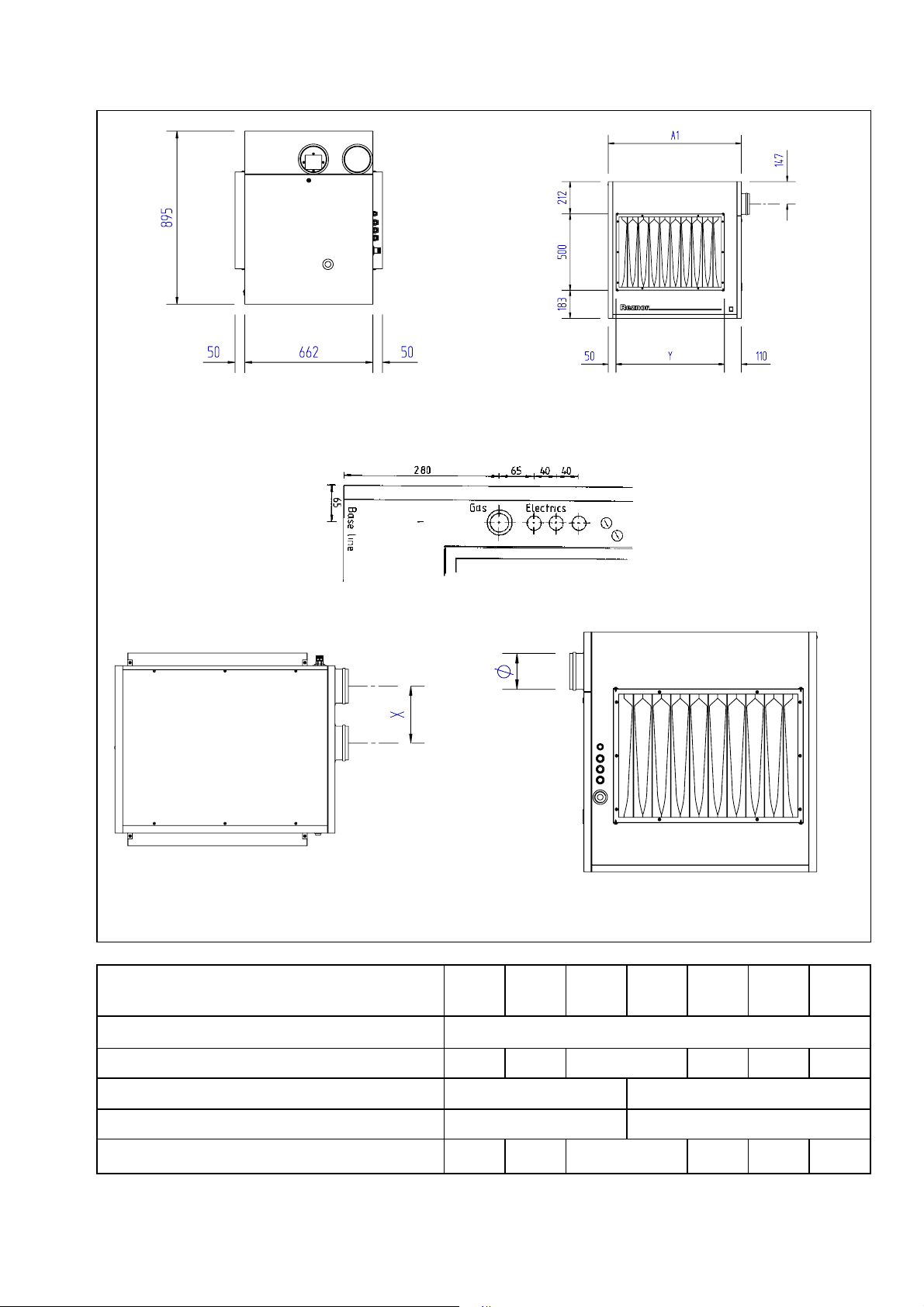
Figure 3. DIMENSIONS
As standard Left hand side (controls side) Front
Gas, electrical & controls connections location
Top plan Rear
Table 5 Dimensions reference figure 3
Model
Dimensions
A1 Width overall
i Flue & combustion air intake socket internal i
X Flue & combustion air intake socket centres
Y Duct flange width front and back
2..25
2..26
520
360
2..30
2..31
590
102
140
620
2..35
2..36
730
570
2..45
2..46
2..55
2..56
870 1080 1360
710
2..75
2..76
132
225
920 1200
2..95
2..96
0505T2D0GBEN
5/21

SECTION 3 INSTALLING
3.1 When installed as an in-line duct heater i.e. not fitted
within an air handling appliance cabinet it is
necessary to ensure that clearance is maintained
around the appliance from combustible materials and
for service access. The clearances necessary to
ensure safety for combustibles is 150 mm on all
sides. Service access should be allowed on the
controls side of the appliance equal to the width of
the air heater plus 200 mm, this distance allows for
the removal of the burner tray assembly, necessary
en servicing the appliance.
3.2 Ensure that the structural elements which will be
used to suspend or support the appliance, are
adequate to carry the weight of the appliance and its
ancillary components i.e. flue system and any
connected duct-work.
3.3 Ensure that the air heater is installed in a level plain.
3.4 If the air heater is to be base mounted in an open
position then it must be secured to supporting
devices.
3.5 4 suspension brackets with holes φ 10.5 mm are
available as optional accessories.
Use 10 mm i rods for suspending the heater when
using the Reznor options.
3.6 If the appliance is to be suspended or base mounted
from cantilever brackets, specially designed wall
brackets should be manufactured to suit the
application respecting the clearances indicated in 3.1
above and the live load factors the appliance will
impose.
3.7 After suspension, the air heater should be rigid so as
to avoid placing a strain on the flue system, gas
services electrical wiring and duct-work.
3.8 Euro-T.. Series D air heaters, wether or not they are
installed within an air handling appliance may be
installed in multiple form as illustrated in figure 4. In
all instances the air flow passed through the
appliance/s should not exceed the volumes required
to ensure that dew point conditions within the
combustion circuits/s as indicated in figure 3 do not
occur.
By-passes should be constructed as necessary to
ensure that the optimum temperature rises are met
taking into account the pressure resistance of the air
heater as indicated in figure 2.
When designing by-pass ducts ensure that the
requirements for service access, flue and controls
connections are maintained. An adjustable damper
should be included within by-pass ducts to enable air
flow pressure and volume to be adjusted after
installation.
When fitting Euro-T.. air heaters in a side by side
configuration it is necessary to specify this requirement
when ordering type D models. Whilst the air may be
passed through the appliance from either end, provision
for locating the thermal over-heat (limit) control device
has to be made so that the air off side (the hottest side)
is monitored for this purpose.
3.8 Figure 5. illustrates the recommended principle that
should be used for the connection of ducts or air
handling appliance element transitions.
A positive seal must be maintained between the air
circuit and the air heater, this is particularly important
when the air heater is installed within an air handling
cabinet. A neutral pressure zone around the appliance
must be maintained to ensure that the atmospheric
burner operates at all times at normal ambient pressure.
3.9 Figure 6 illustrates some of the situations to be avoided
when connecting an air handler to the appliance. A rule
of connecting a straight length of duct equal to 3 times
an equivalent duct diameter onto the appliance should
be maintained whenever possible. It is essential that an
even air flow is distributed across the heat exchanger to
ensure that the heat is scrubbed from all the exchanger
elements thus preventing hot spots which will greatly
reduce the working life of the air heater.
Always avoid installing a centrifugal fan so that the swirl
effect created by the direction of rotation is counter
directive. As well as the effect of uneven air flows,
excessive loss of static pressure is created resulting in
inefficiency of the fan.
Where it is necessary to connect a transition section as
part of the connection then the degree of taper in any
plain should not be greater than 15E. Abrupt transitions
create excessive pressure drops and lead to uneven air
distribution across the air heater.
0505T2D0GBEN
6/21
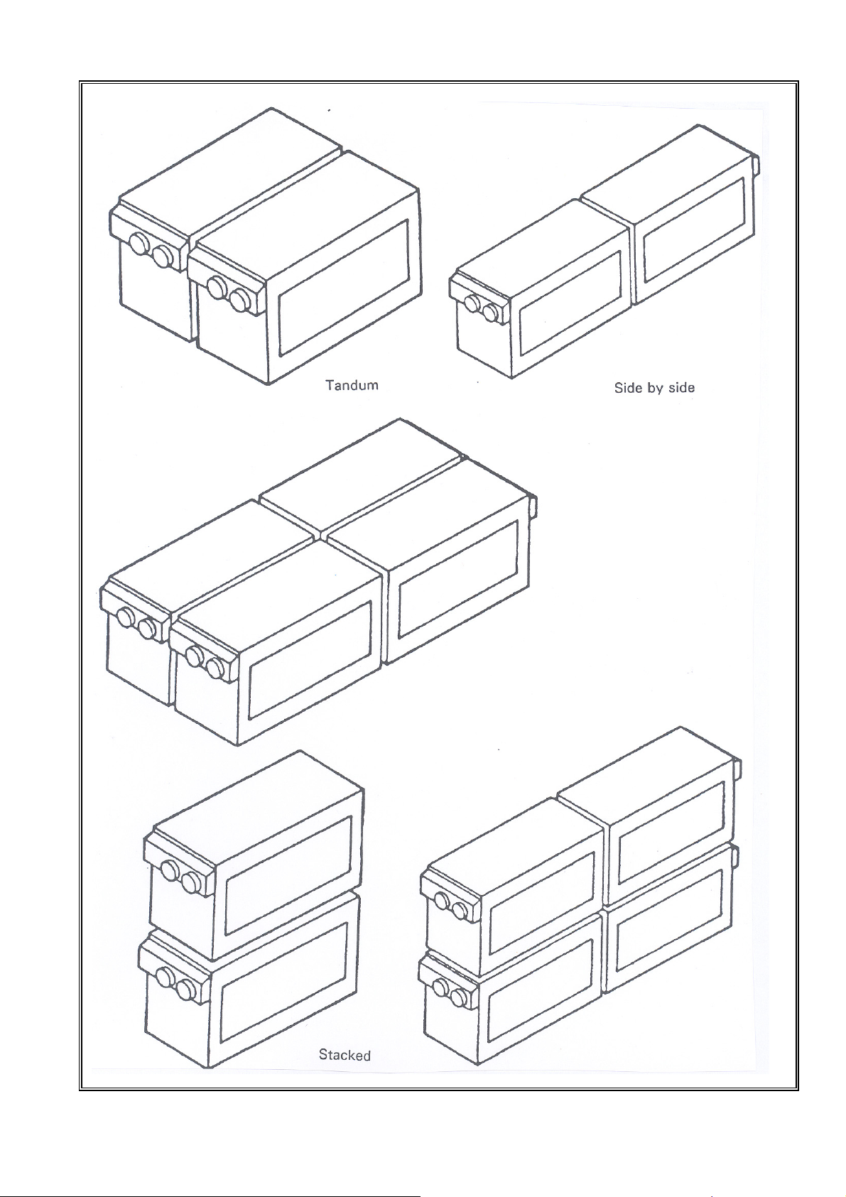
Figure 4. Arrangements for applying multi-heater combinations
0505T2D0GBEN
7/21
 Loading...