


|
|
Form P-RG/RP/RBL (Version 09-14) |
|
|
® |
Obsoletes Form P-RG/RP/RBL (Version C.3) |
|
|
|
|
|
|
|
Applies to: |
Replacement Parts for |
|
IMPORTANT |
Model Series RG, RP, HRPD, RGB, RPB, |
|
1. |
Always include complete heater model and serial number |
RGBL, RPBL, RPDBL, PGBL, RBA, |
|
|
so that any specification change can be considered for |
RBHA, and RBL (including prefixes |
|
|
parts shipment. It can save time and expense. |
||
2. |
Specifications are subject to change without notice. |
|
"C", "H", and "HC") |
3.We reserve the right to substitute functional replacements.
4.Order by Part No.; not Heater Option Designation.
|
|
|
|
|
|
|
|
|
|
|
|
|
|
Duct Furnace Models |
Index |
|
|
E |
|
|
|
|
|
P |
|
|
|
|
|
|
|
|
|
|
|
|
|
|
|
|
RG* |
|||
|
|
|
|
|
|
|
|
|
|
|
||||
B |
|
|
Electrical Component Locations |
6 |
|
Replacement Parts Tag |
2 |
|
||||||
Bearing 22, 43 |
|
Electrical Components 8 |
|
|
Pilot 11 |
|
|
|
|
|
||||
|
F |
|
|
|
|
|
Potentiometer 7, 10, 23 |
|
||||||
Bearing Support 21 |
|
|
|
|
|
|
RP |
|||||||
|
|
|
|
|
|
R |
|
|
|
|
||||
Blower 20, 21 |
|
Fan Control 6 |
|
|
|
|
|
|
|
|
|
|||
Model RBL/RBA/RBHA Blower |
Dirty Filter Pressure Switch 6 |
|
|
Rating Plate |
2 |
|
|
|
|
|||||
Cabinets |
43, 44 |
|
Filter Rack 21 |
|
|
|
|
References |
1 |
|
|
|
HRPD |
|
Burner Rack |
16 |
|
Filters 37 |
|
|
|
|
|
Carryover Regulator |
17 |
|
|||
C |
|
|
Firestat 8 |
|
|
|
|
|
Relay 10 |
|
|
|
|
|
PGBL Furnace Cabinet 13 |
Flue Collar Assembly 12 |
|
|
Time Delay Relay 6, 9 |
|
|
||||||||
Flue Collection Box 12, 13, 14 |
|
|
Relay Chart |
5 |
|
|
|
|
||||||
RG Cabinet and Flue Box Parts 12 |
|
|
|
|
|
Packaged Models |
||||||||
Freezestat 8 |
|
|
|
|
|
Remote Console 39 |
|
|
||||||
RP Cabinet and Collection Box |
|
|
|
|
|
|
|
|||||||
Freezestat, Auto Reset 6 |
|
|
S |
|
|
|
|
|
||||||
Parts 14 |
|
|
|
|
|
|
|
|
|
|||||
Cabinet Connector & Filler Parts |
Fuse 7, 9 |
|
|
|
|
|
Sensor 8 |
|
|
|
|
RGB* |
||
G |
|
|
|
|
|
|
|
|
|
|||||
for Multiple Furnaces 12, 14 |
|
|
|
|
|
Serial Number 3 |
|
|
|
|||||
Cabinet Parts for "BL" Type Blower |
Gas Pressure Switch 6 |
|
|
Heat Shields |
9 |
|
|
|
|
|||||
Cabinet 20 |
|
Gas Valve - See Form P-VALVES |
|
Holding Coils for IEC Starters 30 |
|
|||||||||
Cabinet Parts for "B" Type Blower |
Gear Motor Kit 15 |
|
|
Starters 7, 27, 28, 30 |
|
RPB |
||||||||
Cabinet 19 |
|
H |
|
|
|
|
|
Air Proving Switch 7 |
|
|
||||
Certification |
3 |
|
|
|
|
|
|
Auxiliary End Switch |
23 |
|
||||
|
Heat Exchanger 16 |
|
|
|
||||||||||
Combustion Air Pressure Switch 6 |
|
|
Blower Air Flow Switch |
10 |
|
|||||||||
Outside Air Inlet Hood 40 |
|
|
|
|||||||||||
Packaged System Configurations |
|
|
Combustion Air Switch 8 |
|
||||||||||
I |
|
|
|
|
|
|
||||||||
4 |
|
|
|
|
|
|
|
Gas Pressure Switch 9 |
|
|
||||
Contactor 7, 9 |
|
Ignition Controller |
6, 8 |
|
|
Pressure Null Switch |
23 |
RGBL* |
||||||
2-Stage Controller 6 |
|
Interface Module |
23 |
|
|
|
Pressure Switch 9 |
|
|
|||||
Mixed Air Controller |
23 |
L |
|
|
|
|
|
Toggle Switch 11 |
|
|
|
|||
Cooling Coil Cabinet |
40 |
Limit 10 |
|
|
|
|
|
T |
|
|
|
|
|
|
Roof Curbs 42 |
|
Reverse Flow Limit 10 |
|
|
Temperature Control |
9 |
|
|
||||||
D |
|
|
Limit Control |
6, 9 |
|
|
|
|
||||||
|
|
|
|
Temperature Controller |
7 |
RPBL |
||||||||
Discharge Damper and Controls |
Line Voltage |
5 |
|
|
|
|
Terminal Blocks 7 |
|
|
|||||
|
|
|
|
|
|
|
||||||||
42 |
|
|
M |
|
|
|
|
|
Thermostats 39 |
|
|
|
||
Damper Linkage 24, 25, 26 |
Manifold 16 |
|
|
|
|
|
Transformer |
5, 10 |
|
|
|
|||
Dampers and Controls 22 |
Special Manifolds |
18 |
|
|
|
V |
|
|
|
|
|
|||
DDC Control 11 |
|
Blower Motor |
27, 28, 30 |
|
|
Manual Gas Valves 17 |
|
|
||||||
Disconnect Switch 39 |
Gear Motor AG39,40,41,42 15 |
|
|
|
|
|||||||||
|
|
Variable Frequency Drives 27 |
|
|||||||||||
Door Latch Kit 19, 21, 44 |
Motor Adjustment Bracket 20, 43 |
|
|
|||||||||||
|
Vertical Vent Kit 14 |
|
|
|
||||||||||
Downturn Plenum 42 |
Motor Mounting Bolts 22, 43 |
|
|
|
|
|
||||||||
|
|
Vent Cap 12 |
|
|
RPDBL |
|||||||||
Drives - Model RBHA 36 |
Motor Mounting Plate 20, 43 |
|
|
|
|
|||||||||
|
|
Vent Cap Extension 13 |
|
|||||||||||
Drives - Model Series (H)(C)RGB, |
O |
|
|
|
|
|
Venter Motor 13, 15 |
|
|
|
||||
(H)(C)RPB, and Model RBA 31 |
|
|
|
|
|
|
|
|
||||||
Orifice 17 |
|
|
|
|
|
Vent Limiter 9 |
|
|
|
|||||
Drives - Model Series RGBL, |
Convenience Outlet 7, 9 |
|
|
Z |
|
|
|
|
PGBL* |
|||||
RPBL, PGBL and RBL 34 |
|
|
|
|
|
|
||||||||
Ductstat 6, 8 |
|
Overload 27, 29 |
|
|
|
|
"Z" Baffle 13 |
|
|
|
||||
|
|
|
|
|
|
|
|
|
|
|||||
|
|
|
|
|
|
|
|
|
|
|
|
|
|
|
References (Download these forms at www.ReznorHVAC.com): |
|
|
|
|
|
Blower Cabinets |
||||||||
|
|
|
|
|
RBA* |
|||||||||
Subject |
|
|
|
|
|
|
|
|
Form |
|
|
|
|
|
|
|
|
|
|
|
|
|
|
|
|
|
|
||
Installation/Operation - Model Series RPBL Packaged Systems.............. |
I-SSCBL/RPBL |
|
|
|
|
|
||||||||
Installation/Operation - Model Series RP and HRPD Duct Furnaces............. |
|
|
I-RP/HRPD |
|
|
|
|
|
||||||
Installation/Operation - Model Series RPB Packaged Systems............................... |
|
|
I-RPB |
|
|
|
|
|
||||||
Installation - Model RBL Blower Cabinet................................................................... |
|
|
|
|
|
I-RBL |
|
|
|
|
RBHA* |
|||
Limited Warranty............................................................................................................ |
|
|
|
|
|
|
|
W |
|
|
|
|
||
Replacement Components for Optional Evaporative Cooling Modules................. |
|
|
P-REC |
|
|
|
|
RBL |
||||||
Replacement Gas Valves, Ignition Controllers, & Maxitrol Components for |
|
|
|
|
|
|||||||||
Modulation Gas Controls (Options AG 7, 8, 9, 21, 39, 40, 41, & 42) |
|
|
P-VALVES |
|
|
|
|
|
||||||
|
|
|
|
|
|
* Model is no longer |
||||||||
Converting to Other Gases |
|
|
|
|
|
|
CP-GC |
|
|
|
|
|||
|
|
|
|
|
|
|
|
|
|
being manufactured. |
||||
|
|
|
|
|
|
|
|
|
|
|
|
|
|
|
Form P-RG/RP/RBL, P/N 263984R4, Page 1
Duct Furnace Rating Plate
|
|
REZNOR |
|
|
|
|
|
|
|||
|
|
MERCER, PA. USA 16137 |
|
|
|
|
|
||||
Made in Mexico |
|
|
|
|
|
|
|
|
|
|
|
DUCT FURNACE |
|
|
|
|
|
|
|
|
|
|
|
CATEGORY I |
|
|
|
|
|
|
|
|
|
|
|
FOR INDUSTRIAL/COMMERCIAL USE ONLY |
|
|
|
|
|
|
|||||
ANSI Z83.8 [ AA ] - [ A ] |
CGA 2.6 [ AA' ] -M [ A' ] DUCT FURNACE |
|
|
||||||||
MODEL [ |
B |
] [ |
C |
] |
|
|
|
|
|
|
|
SERIAL NO. [ |
D ] |
|
|
|
|
|
|
|
|
|
|
[ E ] VOLTS [ E ] PH [ E ] HZ MAXIMUM TOTAL INPUT [ E ] AMPS |
|
|
|||||||||
TYPE OF GAS: [ F ] |
[ G ] |
|
|
|
|
|
|
|
|
||
ORIFICE SIZE [ J ] DRILL HAS BEEN FACTORY ADJUSTED |
|
|
|
||||||||
FOR USE AT [ |
H ] FEET [ |
I |
] METERS OF ALTITUDE. |
|
|
|
|
||||
|
|
|
|
|
|
SEA LEVEL ALT. ADJUSTED |
|||||
NORMAL INPUT |
|
|
|
|
[ |
R |
] |
[ |
K |
]BTU/HR. |
|
OUTPUT CAPACITY |
|
|
|
|
[ |
S |
] |
[ |
L |
]BTU/HR. |
|
MINIMUM INPUT(2,M,MB,MV MODELS) |
[ |
T |
] |
[ |
M |
]BTU/HR. |
|||||
NORMAL MANIFOLD PRESSURE |
|
|
|
|
[ |
N |
] IN.W.C. |
||||
MIN. PERMISSIBLE GAS SUPPLY PRESSURE |
|
|
|
|
|
|
|||||
FOR PURPOSE OF INPUT ADJUSTMENT. |
|
|
|
[ |
O |
] IN.W.C. |
|||||
MAXIMUM THROUGHPUT |
[ |
P |
] C.F.M. |
|
|
|
|
|
|
||
MINIMUM THROUGHPUT |
[ |
Q |
] C.F.M. |
|
|
|
|
|
|
||
CLEARANCES TO COMBUSTIBLE CONSTRUCTION: VENT CAP-10' , BOTTOM- 3", FLUE CONNECTION-6", SERVICE SIDEWIDTH OF UNIT, OPPOSITE SIDE-6" THIS UNIT SHALL BE INSTALLED ON THE POSITIVE PRESSURE SIDE OF THE AIR CIRCULATING BLOWER.
THIS UNIT MAY BE INSTALLED DOWNSTREAM FROM A REFRIGERATION SYSTEM (USE DRAIN OPTION CS1).
THIS UNIT MAY BE USED WITH DUCTS.
THIS UNIT IS FOR OUTDOOR INSTALLATION ONLY.
MINIMUM OPERATIONAL AMBIENT AIR TEMPERATURE: -40 DEG. F
THIS UNIT IS FOR USE WITH NATURAL GAS AND PROPANE. A CONVERSION KIT AS SUPPLIED BY THE MANUFACTURER, SHALL BE USED TO CONVERT THIS DUCT FURNACE TO THE ALTERNATE FUEL.
FOR ALTERNATE INSTALLATIONS USE THE LATEST EDITIONS OF THE APPROPRIATE STANDARD LISTED BELOW:
FOR AIRCRAFT HANGERS |
USE STANDARD ANSI/NFPA 409 |
FOR PARKING STRUCTURES |
USE STANDARD ANSI/NFPA 88A |
FOR REPAIR GARAGES |
USE STANDARD ANSI/NFPA 88B |
Key to Duct Furnace Rating Plate
A = Standard |
M = Minimum Input (altitude |
B = Model and Size |
adjusted) |
C = Date of Manufacturer |
N = Normal Manifold Pressure |
D = Serial No. |
O = Minimum Gas Supply |
E = Volts/PH/Hz/Amps |
Pressure |
F & G = Natural Gas or Propane |
P = Maximum Air Throughput |
H & I = Altitude |
Q = Minimum Air Throughput |
J = Orifice Drill Size |
R = Normal Input (sea level) |
K = Normal Input (altitude adjusted) S = Thermal Output (sea level)
L = Thermal Output (altitude |
T = Minimum Input (sea level) |
|
adjusted) |
|
|
De-Coding a Serial No. |
|
|
Sample: |
S BKI 95 W8 N 12345 MV3 |
|
1 | 2 | 3 | 4 | 5 | 6 | 7
1 = Stainless steel heat exchanger (with an aluminized heat exchanger, there is no letter suffix
2 = Date code (see page 3)
3 = Pilot code (Reference Form P-VALVES)
4 = Valve code (Reference Form P-VALVES) 5 = N is natural gas; L is propane gas
6 = Consecutive number
7 = Maxitrol system (optional)
Blower Cabinet Rating Plate on Certified Packaged Units (see table on page 3)
REZNOR
MERCER, PA., U.S.A. 16137
PACKAGED DUCT FURNACE
FOR INDUSTRIAL/COMMERCIAL USE ONLY
DESIGN CERTIFIED FOR A.G.A REQUIREMENTS UNDER
[ A ] PACKAGED DUCT FURNACE STANDARD |
|
|||
MODEL [ |
B |
] |
[ C |
] |
SERIAL NO. |
|
|
|
[ D ] |
HP
[ E ] VOLTS [ E ] PH [ E ] HZ MAXIMUM TOTAL INPUT [ E ] AMPS
IF EQUIPPED WITH R.E.C. OPTION, ADD [ V ] AMPS |
|
|
|
EQUIPPED FOR OPERATION AT AN AIR FLOW OF [ |
F |
] SCFM |
|
AGAINST A STATIC PRESSURE OF [ G ] INCHES WATER COLUMN. |
|||
DRIVE NO. [ H ] |
WIRING DIAGRAM [ |
I |
] |
SEE MANUFACTURER'S INSTRUCTIONS FOR OTHER AIR FLOW CAPACITIES.
FILTERS, WHEN USED, MUST BE INSTALLED EXTERNAL TO THE HEATING CASING.
REFER TO THE RATING PLATE OF THE DUCT FURNACE FOR ADDITIONAL INFORMATION.
Replacement Parts Tag - Each unit has a replacement parts tag that includes the Model No. and the Serial No. as well as a list of original common replacement parts.
Always provide the full model and serial numbers when ordering replacement parts.
Key to Cabinet Rating Plate
A = Standard |
F = SCFM |
B = Model |
G = Static Pressure (w.c.) |
C = Date of Manufacture |
H = Drive AM Option Code |
D = Motor Horsepower |
I = Wiring Diagram No. |
E = Volts/Phase/Hertz/Amps |
|
Identification Plate on Blower Cabinets Manufactured Prior to Package Certification (see dates on page 3)
|
|
|
MODEL NUMBER |
|
SERIAL NUMBER |
|||
|
|
® |
DRIVE NO. |
WIRING DIAGRAM NO. |
|
|||
|
|
|
CFM _____ AT____ IN. W.C. MAX. E.S.P. AND ____ HP |
|||||
|
|
|
|
VOLTS |
PHASE |
HERTZ |
AMPERES |
|
HP |
|
|
|
|
|
|
||
Single-Speed Motors |
2-Speed Motors |
|
|
|||||
Codes |
|
|
|
|
|
|
|
|
Code |
|
HP |
Code |
HP |
|
|
||
|
|
|
|
|
||||
|
|
05 |
|
1 |
20 |
1/.44 |
|
|
|
|
06 |
|
1-1/2 |
21 |
1.5/.68 |
|
|
|
|
07 |
|
2 |
22 |
2/.88 |
|
|
|
|
08 |
|
3 |
23 |
3/1.3 |
|
|
|
|
09 |
|
5 |
24 |
5/2.2 |
|
|
|
|
11 |
|
7-1/2 |
25 |
7.5/3.3 |
|
|
|
|
12 |
|
15 |
26 |
10/4.4 |
|
|
|
|
13 |
|
10 |
|
|
|
|
|
|
14 |
|
20 |
|
|
|
|
Form P-RG/RP/RBL, P/N 263984R4, Page 2

First Element of the Serial Number - Date of Manufacture
Year |
Jan |
Feb |
Mar |
Apr |
May |
June |
July |
Aug |
Sept |
Oct |
Nov |
Dec |
1989 |
AOA |
AOB |
AOC |
AOD |
AOE |
AOF |
AOG |
AOH |
AOI |
AOJ |
AOK |
AOL |
1990 |
APA |
APB |
APC |
APD |
APE |
APF |
APG |
APH |
API |
APJ |
APK |
APL |
1991 |
AQA |
AQB |
AQC |
AQD |
AQE |
AQF |
AQG |
AQH |
AQI |
AQJ |
AQK |
AQL |
1992 |
ARA |
ARB |
ARC |
ARD |
ARE |
ARF |
ARG |
ARH |
ARI |
ARJ |
ARK |
ARL |
1993 |
ASA |
ASB |
ASC |
ASD |
ASE |
ASF |
ASG |
ASH |
ASI |
ASJ |
ASK |
ASL |
1994 |
ATA |
ATB |
ATC |
ATD |
ATE |
ATF |
ATG |
ATH |
ATI |
ATJ |
ATK |
ATL |
1995 |
AUA |
AUB |
AUC |
AUD |
AUE |
AUF |
AUG |
AUH |
AUI |
AUJ |
AUK |
AUL |
1996 |
AVA |
AVB |
AVC |
AVD |
AVE |
AVF |
AVG |
AVH |
AVI |
AVJ |
AVK |
AVL |
1997 |
AWA |
AWB |
AWC |
AWD |
AWE |
AWF |
AWG |
AWH |
AWI |
AWJ |
AWK |
AWL |
1998 |
AXA |
AXB |
AXC |
AXD |
AXE |
AXF |
AXG |
AXH |
AXI |
AXJ |
AXK |
AXL |
1999 |
AYA |
AYB |
AYC |
AYD |
AYE |
AYF |
AYG |
AYH |
AYI |
AYJ |
AYK |
AYL |
2000 |
AZA |
AZB |
AZC |
AZD |
AZE |
AZF |
AZG |
AZH |
AZI |
AZJ |
AZK |
AZL |
2001 |
BAA |
BAB |
BAC |
BAD |
BAE |
BAF |
BAG |
BAH |
BAI |
BAJ |
BAK |
BAL |
2002 |
BBA |
BBB |
BBC |
BBD |
BBE |
BBF |
BBG |
BBH |
BBI |
BBJ |
BBK |
BBL |
2003 |
BCA |
BCB |
BCC |
BCD |
BCE |
BCF |
BCG |
BCH |
BCI |
BCJ |
BCK |
BCL |
2004 |
BDA |
BDB` |
BDC |
BDD |
BDE |
BDF |
BDG |
BDH |
BDI |
BDJ |
BDK |
BDL |
2005 |
BEA |
BEB |
BEC |
BED |
BEE |
BEF |
BEG |
BEH |
BEI |
BEJ |
BEK |
BEL |
2006 |
BFA |
BFB |
BFC |
BFD |
BFE |
BFF |
BFG |
BFH |
BFI |
BFJ |
BFK |
BFL |
2007 |
BGA |
BGB |
BGC |
BGD |
BGE |
BGF |
BGG |
BGH |
BGI |
BGJ |
BGK |
BGL |
2008 |
BHA |
BHB |
BHC |
BHD |
BHE |
BHF |
BHG |
BHH |
BHI |
BHJ |
BHK |
BHL |
2009 |
BIA |
BIB |
BIC |
BID |
BIE |
BIF |
BIG |
BIH |
BII |
BIJ |
BIK |
BIL |
2010 |
BJA |
BJB |
BJC |
BJD |
BJE |
BJF |
BJG |
BJH |
BJI |
BJJ |
BJK |
BJL |
2011 |
BKA |
BKB |
BKC |
BKD |
BKE |
BKF |
BKG |
BKH |
BKI |
BKJ |
BKK |
BKL |
2012 |
BLA |
BLB |
BLC |
BLD |
BLE |
BLF |
BLG |
BLH |
BLI |
BLJ |
BLK |
BLL |
2013 |
BMA |
BMB |
BMC |
BMD |
BME |
BMF |
BMG |
BMH |
BMI |
BMJ |
BMK |
BML |
2014 |
BNA |
BNB |
BNC |
BND |
BNE |
BNF |
BNG |
BNH |
BNI |
BNJ |
BNK |
BNL |
2015 |
BOA |
BOB |
BOC |
BOD |
BOE |
BOF |
BOG |
BOH |
BOI |
BOJ |
BOK |
BOL |
2016 |
BPA |
BPB |
BPC |
BPD |
BPE |
BPF |
BPG |
BPH |
BPI |
BPJ |
BPK |
BPL |
2017 |
BQA |
BQB |
BQC |
BQD |
BQE |
BQF |
BQG |
BQH |
BQI |
BQJ |
BQK |
BQL |
2018 |
BRA |
BRB |
BRC |
BRD |
BRE |
BRF |
BRG |
BRH |
BRI |
BRJ |
BRK |
BRL |
2019 |
BSA |
BSB |
BSC |
BSD |
BSE |
BSF |
BSG |
BSH |
BSI |
BSJ |
BSK |
BSL |
2020 |
BTA |
BTB |
BTC |
BTD |
BTE |
BTF |
BTG |
BTH |
BTI |
BTJ |
BTK |
BTL |
Date Series was
Introduced or Recertified
(may affect parts selection)
Beginning January 2000, heaters display a CSA label certifying that the unit or system has been approved to ANSI Standards for use in the United States or to C.G.A. Standards for use in Canada.
Duct Furnace Certification |
|
|
(NOTE: Prefix "H" indicates |
|
Model |
Original Agency |
Introduced |
Recertified |
|
(H)(C)(HC) RP |
A.G.A. |
2/90 |
-- |
higher CFM capacity; "C" |
(H) RP |
A.G.A. |
-- |
Series 8 - 5/95 |
indicates higher thermal |
(H)(C)(HC) RG |
A.G.A. |
2/90 |
Series 8 - 5/95 |
efficiency; "HC" indicates |
(H) RG |
C.G.A. |
5/90 |
Series 8 - 5/95 |
higher CFM capacity and |
(H) RP |
C.G.A. |
5/90 |
Series 8 - 5/95 |
thermal efficiency. ) |
Packaged Unit Certification |
|
|
|
|
Model |
Original Agency |
Certified |
|
|
(H)(C)(HC) RGB |
A.G.A. |
2/96 |
|
|
(H) RPB |
A.G.A. |
2/96 |
|
|
RPBL, (C)RGBL |
A.G.A. |
11/96 |
|
|
PGBL |
A.G.A. |
3/97 |
|
|
(H)(C)(HC) RGB |
C.G.A. |
8/96 |
|
|
(H) RPB |
C.G.A. |
8/96 |
|
|
RPBL, (C)RGBL |
C.G.A. |
8/97 |
|
|
PGBL |
C.G.A. |
8/97 |
|
|
Descriptions
* Models are no longer manufactured.
Also, except for duct furnace Model HRPD, "H", "C", and "HC" Models are no longer manufactured.
Model |
No. of |
Type |
Capacity Ranges |
Thermal |
Vent |
Installation |
|
Sizes |
Efficiency |
||||||
*PGBL |
3 |
Packaged |
400-1200 MBH Input/ |
80% |
Power |
Indoor |
|
3300-13500 CFM |
|||||||
|
|
|
|
|
|
||
*RG |
11 |
Duct Furnace |
75-400 MBH Input |
78% |
Gravity |
Outdoor |
|
*RGB |
11 |
Packaged |
75-400 MBH Input/ |
78% |
Gravity |
Outdoor |
|
600-7100 CFM |
|||||||
|
|
|
|
|
|
||
*RGBL |
7 |
Packaged |
400-1200 MBH Input/ |
78% |
Gravity |
Outdoor |
|
3300-13500 CFM |
|||||||
|
|
|
|
|
|
||
RP |
9 |
Duct Furnace |
125-400 MBH Input |
80% |
Power |
Outdoor |
|
HRPD |
8 |
2 Duct Furnaces |
250-800 MBH Input |
80% |
Power |
Outdoor |
|
RPB |
9 |
Packaged |
125-400 MBH Input/ |
80% |
Power |
Outdoor |
|
1025-7100 CFM |
|||||||
|
|
|
|
|
|
||
*RPBL |
7 |
Packaged |
400-1200 MBH Input/ |
80% |
Power |
Outdoor |
|
3300-13500 CFM |
|||||||
|
|
|
|
|
|
||
*RPDBL |
5 |
Packaged |
800-1600 MBH Input/ |
80% |
Power |
Outdoor |
|
6600-22000 CFM |
|||||||
|
|
|
|
|
|
||
*RBA |
1 |
Blower only |
1500-5000 CFM |
-- |
-- |
Indoor/Outdoor |
|
*RBHA |
1 |
Blower only |
1500-5000 CFM |
-- |
-- |
Indoor/Outdoor |
|
RBL |
1 |
Blower only |
5000-15000 CFM |
-- |
-- |
Indoor/Outdoor |
Form P-RG/RP/RBL, P/N 263984R4, Page 3
Dual Duct Furnace and Packaged System (Blower/Furnace) Model Configurations
Outdoor Dual Duct Furnaces in Series, Model
HRPD 250, 300, 350, 400, 500, 600, 700, 800
250 = 2(HRP125); 500 = 2(HRP250);
300 = 2(HRP150); 600 = 2(HRP300);
350 = 2(HRP175); 700 = 2(HRP350);
400 = 2(HRP200); 800 = 2(HRP400)
Outdoor (H)(C)RGB and (H)RPB Packaged Systems
1. |
Model RG, CRG, HRG, HCRG, RP, or HRP duct |
|
|
|
|
|
|
|
|
|
"B" |
||
|
furnace coupled with a "B" Blower Cabinet. |
|
|
|
|
|
|
|
|
|
|
||
2. |
Optional outside air hood, downturn plenum, coil |
|
|
|
|
Cabinet |
|
|
|
|
|||
|
cabinet (with or without downturn), and evapora- |
|
|
|
|
Duct |
|
|
|
|
|||
|
tive cooling module may be part of the packaged |
|
|
|
|
Furnace |
|
unit. |
|
|
|
|
|
|
|
|
|
|
|
Outdoor (C)RGBL and RPBL Packaged Systems
1.Model HRG, HCRG, or HRP duct furnaces (in quantity and size indicated below) coupled with a "BL" Blower Cabinet.
2.Optional outside air hood, downturn plenum, coil cabinet (with or without downturn), and evaporative cooling module may be part of the packaged unit.
Indoor PGBL Packaged System
1.A PGBL packaged system is a duct furnace (in quantity and size indicated below) coupled with a "BL" Blower Cabinet.
2.Optional downturn plenum, coil cabinet (with or without downturn), and evaporative cooling module may be part of the packaged unit.
|
|
|
|
|
|
"BL" |
|
Packaged |
|
|
Includes One Size 400 Duct Furnace |
|
||||
|
|
|
|
|
|
|
|
|
||||||||
|
|
|
|
|
|
|
Model Series |
|
Size |
250 |
300 |
350 |
400 |
|
|
|
|
|
|
|
|
|
Cabinet |
|
|
|
|
||||||
|
|
|
|
|
|
|
|
|||||||||
|
|
|
|
|
|
|
RGBL/RPBL/PGBL |
|
400 |
-- |
-- |
-- |
1 |
|
|
|
|
|
|
|
|
|
Duct |
|
|
|
|
||||||
|
|
|
|
|
|
|
|
|
|
|
|
|
|
|
|
|
|
|
|
|
|
|
Furnace |
|
|
|
|
|
|
|
|
|
|
|
|
|
|
|
|
|
|
|
|
|
|
|
|
|
|
|
|
|
|
|
|
|
|
|
|
|
|
|
|
|
|
|
|
|
|
|
|
|
|
|
|
|
|
|
|
|
|
|
|
|
|
|
|
|
|
|
"BL" |
|
Packaged |
|
|
Includes Size & Quantity of Furnaces |
|
||||
|
|
|
|
|
|
|
Model Series |
|
Size |
250 |
300 |
350 |
400 |
|
|
|
|
|
|
|
|
|
Cabinet |
|
|
|
|
||||||
|
|
|
|
|
|
|
|
|||||||||
|
|
|
|
|
|
|
RGBL/RPBL |
500 |
2 |
-- |
-- |
-- |
|
|
||
|
|
|
|
|
|
Duct |
|
|
|
|||||||
|
|
|
|
|
|
|
|
|
|
|
|
|
|
|
|
|
|
|
|
|
|
|
|
RGBL/RPBL |
600 |
-- |
2 |
-- |
-- |
|
|
||
|
|
|
|
|
|
Furnace |
|
|
|
|||||||
|
|
|
|
|
|
|
RGBL/RPBL |
700 |
-- |
-- |
2 |
-- |
|
|
||
|
|
|
|
|
|
Duct |
|
|
|
|||||||
|
|
|
|
|
|
|
RGBL/RPBL/PGBL |
800 |
-- |
-- |
-- |
2 |
|
|
||
|
|
|
|
|
|
Furnace |
|
|
|
|||||||
|
|
|
|
|
|
|
|
|
|
|
|
|
|
|
|
|
|
|
|
|
|
|
|
|
|
|
|
|
|
|
|
|
|
|
|
|
|
|
|
|
|
|
|
|
|
|
|
|
|
|
|
|
|
|
|
|
|
|
|
|
|
|
|
|
|
|
|
|
|
|
|
|
|
"BL" |
|
Packaged |
|
|
Includes Size & Quantity of Furnaces |
|
||||
|
|
|
|
|
|
Cabinet |
|
Model Series |
|
Size |
250 |
300 |
350 |
400 |
|
|
|
|
|
|
|
|
|
|
|||||||||
|
|
|
|
|
|
Duct |
|
RGBL/RPBL |
|
1050 |
-- |
-- |
3 |
-- |
|
|
|
|
|
|
|
|
|||||||||||
|
|
|
|
|
|
|
RGBL/RPBL/PGBL |
|
1200 |
-- |
-- |
-- |
3 |
|
|
|
|
|
|
|
|
|
Furnace |
|
|
|
|
||||||
|
|
|
|
|
|
|
|
|
|
|
|
|
|
|
|
|
|
|
|
|
|
|
Duct |
|
|
|
|
|
|
|
|
|
|
|
|
|
|
|
|
|
|
|
|
|
|
|
|
|
|
|
|
|
|
|
|
|
Furnace |
|
|
|
|
|
|
|
|
|
|
|
|
|
|
|
|
Duct |
|
|
|
|
|
|
|
|
|
|
|
|
|
|
|
|
|
|
|
|
|
|
|
|
|
|
|
|
|
|
|
|
|
Furnace |
|
|
|
|
|
|
|
|
|
|
|
|
|
|
|
|
|
|
|
|
|
|
|
|
|
|
|
Outdoor RPDBL Packaged Systems
1.HRP duct furnaces (in quantity and size indicated below) coupled together with two "BL" Blower Cabinets.
2.Optional outside air hoods and downturn plenum cabinets may be part of the packaged unit.
|
|
|
Size 800 |
|
|
Sizes 1000/1200/1400/1600 |
||||||||||||
|
|
|
|
|
|
|
|
"BL" |
|
|
|
|
|
|
|
|
|
"BL" |
|
|
|
|
|
|
|
|
|
|
|
|
|
|
|
|
|
||
|
|
|
|
|
|
|
|
Cabinets |
|
|
|
|
|
|
|
|
|
Cabinets |
|
|
|
|
|
|
|
|
Duct |
|
|
|
|
|
|
|
|
|
|
|
|
|
|
|
|
|
|
|
|
|
|
|
|
|
|
|
|
|
|
|
|
|
|
|
|
|
|
|
|
|
|
|
|
|
|
|
|
|
|
|
|
|
|
|
|
Furnaces |
|
|
|
|
|
|
|
|
|
Duct |
|
|
|
|
|
|
|
|
|
|
|
|
|
|
|
|
|
|
Furnaces |
|
|
|
|
|
|
|
|
|
|
|
|
|
|
|
|
|
|
|
|
|
|
|
|
|
|
|
|
|
|
|
|
|
|
|
|
|
|
|
|
|
|
|
|
|
|
|
|
|
|
|
|
|
|
|
|
|
RPDBL |
Consists of: |
800 |
(2) RPBL 400 Packaged Systems |
1000 |
(2) RPBL 500 Packaged Systems |
1200 |
(2) RPBL 600 Packaged Systems |
1400 |
(2) RPBL 700 Packaged Systems |
1600 |
(2) RPBL 800 Packaged Systems |
NOTE: Replacement parts are not identified for these specific models; look for equivalent RPBL models.
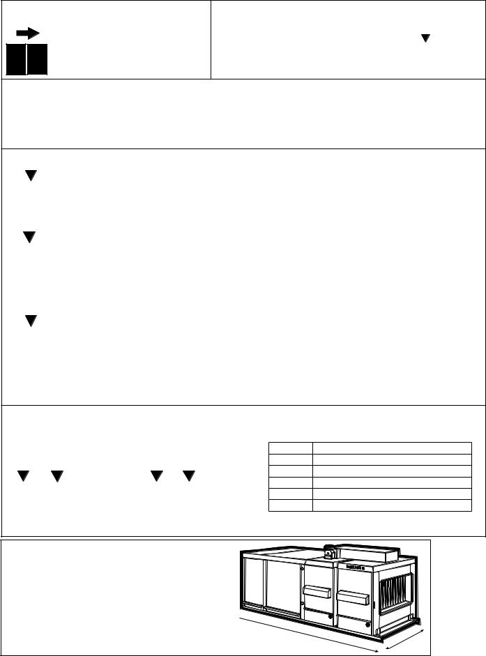
Unit Direction Orientation Diagram - Applies to all models; Model PGBL 800 illustrated
NOTE: Left side controls (illustrated) are standard. Right side controls are optional. If the unit has right side controls, some replacement parts will be affected.
 End (Rear)
Right
Front
t Lef
Form P-RG/RP/RBL, P/N 263984R4, Page 4

Line Voltage Application to Package Configuration
Line Voltage to Furnace or Packaged System
Unit Voltage |
115 |
208 |
230 |
460 |
575 |
Comments |
RG Control Volts In/Out/VA |
115/24/20 |
208/24/20 |
230/24/20 |
460/24/20 |
N/A |
Furnace only |
RGB Motor Voltage |
115 |
208 |
230 |
460 |
575 |
|
RGB Controls Volts In/Out/VA |
115/24/40 |
208/24/40 |
230/24/40 |
460/24/40 |
575/24/200 |
|
RP Control Volts In/Out/VA |
115/24/40 |
208/24/40 |
230/24/40 |
460/24/40 |
N/A |
Furnace only |
HRPD Control Volts In/Out/VA |
115/24/40 |
208/24/40 |
230/24/40 |
460/24/40 |
N/A |
Furnace only |
RPB Motor Voltage |
115 |
208 |
230 |
460 |
575 |
|
RPB Controls Volts In/Out/VA |
115/24/40 |
208/24/40 |
230/24/40 |
460/24/40 |
115/24/40 |
575 to 115V / 300VA Transformer |
RPBL/RGBL/PGBL 400 |
115 |
208 |
230 |
460 |
115 |
575 to 115V / 300VA Transformer |
RPBL/RGBL 500-800; PGBL 800 |
115 |
208 |
230 |
460 |
115 |
575 to 115V / 500VA Transformer |
RPBL/RGBL 1050-1200; PGBL 1200 |
115 |
208 |
230 |
460 |
115 |
575 to 115V / 750VA Transformer |
Quick Reference Charts (NOTE: Consult wiring diagram to verify relays and transformers.)
Relay Chart |
|
|
|
|
|
|
|
|
|
|
|
|
|
|
Relay P/N |
|
|
|
|
|
|
|
|
|
|
|||
|
211411 Relay |
103317* |
|
98118* |
|
|
|
|
|
|
|
259518* or |
|
|
|
|
|
|
206146* |
|||||||||
|
|
|
|
|
|
|
259780 |
|
46233* |
|
|
|
|
262337 |
||||||||||||||
|
|
with Socket |
|
|
|
|
|
|
|
|
|
|
|
|
|
|
|
|
|
|
||||||||
|
|
|
|
|
|
|
|
|
110656 |
beginning |
Order Re- |
|
209164 |
beginning |
Order Re- |
|||||||||||||
|
|
211415 begin- |
Order Replace- |
|
||||||||||||||||||||||||
|
|
ning 9/2011 |
ment Kit 263527 |
|
|
|
02/2010 |
|
placement |
|
|
|
|
12/2010 |
placement |
|||||||||||||
Where Used |
|
|
|
|
|
|
|
Kit 259521 |
|
|
|
|
|
|
Kit 262375 |
|||||||||||||
|
|
|
|
|
|
|
|
|
|
|
|
|
|
|
|
|
|
|
|
|
|
|
||||||
Freezestat Relay |
|
|
X |
|
|
X |
|
|
|
|
|
|
|
|
|
|
|
|
|
|
|
|
|
|
|
|
|
|
Starter Relay |
|
|
|
|
|
|
|
|
|
|
|
|
X |
|
|
|
|
|
|
|
|
|
|
|
|
|
|
|
Summer/Winter Relay (Option BF2) |
|
X |
|
|
|
|
|
|
X |
|
|
|
|
|
|
|
|
|
|
|
|
|
|
|
|
|
||
SPST Relay (BG Option) |
|
X |
|
|
|
|
|
|
X |
|
|
|
|
|
|
|
|
|
|
|
|
|
|
|
|
|
||
SPDT Relay (BG Option) |
|
X |
|
|
X |
|
|
|
|
|
|
|
|
|
|
|
|
|
|
|
|
|
|
|
|
|
|
|
Illinois School Code Controls (Option |
|
|
|
|
X |
|
|
|
X |
|
|
|
|
|
|
|
|
|
|
|
|
|
|
|
|
|
||
BM12) |
|
|
|
|
|
|
|
|
|
|
|
|
|
|
|
|
|
|
|
|
|
|
|
|
|
|||
|
|
|
|
|
|
|
|
|
|
|
|
|
|
|
|
|
|
|
|
|
|
|
|
|
|
|
|
|
Two-Speed Motor Relay |
|
|
|
|
|
|
|
|
|
|
|
X |
|
|
|
|
|
|
|
|
|
|
|
|
|
|
||
Two-Speed Motor Speed Relay |
|
|
|
|
|
|
|
|
|
|
|
X |
|
|
|
|
|
|
|
|
|
|
|
|
|
|
||
IRI Gas Controls (Option BM13) |
|
|
|
|
|
|
|
|
X(4) |
|
|
|
|
|
|
|
|
|
|
|
|
|
|
|
|
|
||
Discharge Damper Relays |
|
X (2) |
|
|
X(2) |
|
|
|
|
|
|
|
|
|
|
|
|
|
|
|
|
|
|
|
|
|
|
|
Time Delay Relay Venter (RP Series & |
|
|
|
|
|
|
|
|
|
|
|
|
|
|
X |
|
X |
|
|
|
|
|
|
|
|
|
|
|
PGBL) |
|
|
|
|
|
|
|
|
|
|
|
|
|
|
|
|
|
|
|
|
|
|
|
|
|
|
||
|
|
|
|
|
|
|
|
|
|
|
|
|
|
|
|
|
|
|
|
|
|
|
|
|
|
|
|
|
Blower Relay |
|
|
X |
|
|
|
|
|
|
X |
|
|
|
|
|
|
|
|
|
|
|
|
|
|
|
|
|
|
DDC Interface Relay (Options D1, D2, |
|
|
|
X (2or3) |
|
|
|
|
|
|
|
|
|
|
|
|
|
|
|
|
|
|
|
|
|
|||
D3, D4) |
|
|
|
|
|
|
|
|
|
|
|
|
|
|
|
|
|
|
|
|
|
|
|
|
|
|||
|
|
|
|
|
|
|
|
|
|
|
|
|
|
|
|
|
|
|
|
|
|
|
|
|
|
|
|
|
Fan/Blower Control (replaced |
|
|
|
|
|
|
|
|
|
|
|
|
|
|
|
|
|
|
|
|
X |
|
|
|
|
|
||
temperature activated fan control 12/04) |
|
|
|
|
|
|
|
|
|
|
|
|
|
|
|
|
|
|
|
|
|
|
|
|
|
|||
|
|
|
|
|
|
|
|
|
|
|
|
|
|
|
|
|
|
|
|
|
|
|
|
|
|
|
||
Gas Control Options AG39, AG40, AG41, |
|
|
|
|
|
|
|
|
|
|
|
|
|
|
|
|
|
|
|
|
|
|
X |
|
X |
|||
AG42 |
|
|
|
|
|
|
|
|
|
|
|
|
|
|
|
|
|
|
|
|
|
|
|
|
||||
|
|
|
|
|
|
|
|
|
|
|
|
|
|
|
|
|
|
|
|
|
|
|
|
|
|
|
|
|
For additional information, see CODE(S): |
|
|
34, 35 |
|
|
|
|
|
|
33 |
|
|
12 |
|
|
|
14 |
138 |
|
|
||||||||
|
On Page |
|
|
|
10 |
|
|
|
|
|
|
10 |
|
|
9 |
|
|
|
9 |
15 |
|
|
||||||
* These P/N's are for reference only; the parts are no longer available. |
|
|
|
|
|
|
|
|
|
|
|
|
|
|||||||||||||||
Transformer Chart |
|
|
|
|
|
|
|
|
|
|
|
|
|
|
|
|
|
|
|
|
|
|
|
|
|
|
|
|
|
Transformer |
|
ControlsRG |
|
ControlsRP |
ControlsRGB(L) |
|
RPB(L)Controls |
|
ControlsPGBL |
|
RBHA/RBA/RBL Controls |
RPBL/Line575V PGBL400 |
|
RPBL400Line575V - 800/1200PGBL800; |
RPBLLine575V |
1200-1050 |
|
ManifoldIRI |
ManifoldFM |
OptioninUsedD1-4 building'sfrom(DDC |
controlenvironmental system) |
|
DamperDischarge |
||||
|
|
|
|
|
|
|
|
|
|
|
|
|
|
|
|
|
|
|
|
|
|
|
|
|
|
|
||
Transformer |
Volts |
|
|
|
|
|
|
|
|
|
|
|
|
|
|
|
|
|
|
|
|
|
|
|
|
|
|
|
P/N |
|
|
|
|
|
|
|
|
|
|
|
|
|
|
|
|
|
|
|
|
|
|
|
|
|
|
|
|
|
|
|
|
|
|
|
|
|
|
|
|
|
|
|
|
|
|
|
|
|
|
|
|
|
|
|
|
|
|
In |
Out |
VA |
|
|
|
|
|
|
|
|
|
|
|
|
|
|
|
|
|
|
|
|
|
|
|
|
|
|
|
|
|
|
|
|
|
|
|
|
|
|
|
|
|
|
|
|
|
|
|
|
|
|
|
|
|
|
103054 |
115 |
24 |
20 |
X |
|
|
|
|
|
|
|
|
|
|
|
|
|
|
|
|
|
|
|
|
|
|
|
|
103055 |
115 |
24 |
40 |
|
|
X |
X |
|
X |
|
|
|
X |
|
|
|
|
|
|
|
|
|
X |
|
X |
|||
103497 |
208-230 |
24 |
40 |
|
|
|
|
|
|
|
|
|
|
X |
|
|
|
|
|
|
|
|
|
X |
|
X |
||
103498 |
480 |
24 |
40 |
|
|
|
|
|
|
|
|
|
|
X |
|
|
|
|
|
|
|
|
|
X |
|
X |
||
38634 |
115 |
24 |
200 |
|
|
|
|
|
|
|
|
X |
|
|
|
|
|
|
|
|
|
|
|
|
|
|
|
|
39095 |
208-230-460-575 |
24 |
200 |
|
|
|
X |
|
X |
|
X |
|
X |
|
|
|
|
|
|
|
|
|
|
|
|
|
||
105202 |
208-230-460-575 |
115 |
300 |
|
|
|
|
|
|
X |
|
X |
|
|
|
X |
|
|
|
|
|
|
X |
X |
|
|
|
|
86998 |
208 |
115 |
500 |
|
|
|
|
|
|
|
|
|
|
|
|
|
|
|
|
|
|
|
X |
|
|
|
|
|
86997 |
230-460 |
115 |
500 |
|
|
|
|
|
|
|
|
|
|
|
|
|
|
|
|
|
|
|
X |
|
|
|
|
|
112641 |
575 |
115 |
500 |
|
|
|
|
|
|
|
|
|
|
|
|
|
|
X |
|
|
|
|
|
|
|
|
|
|
112642 |
575 |
115 |
750 |
|
|
|
|
|
|
|
|
|
|
|
|
|
|
|
X |
|
|
|
|
|
|
|
||
Form P-RG/RP/RBL, P/N 263984R4, Page 5

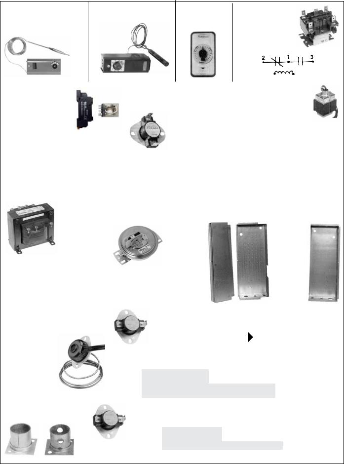
Furnace Electrical Component Locations
("B" Cabinet is illustrated; control locations are the same in the larger capacity "BL" Cabinets)
Venter assembly and combustion air switch on indoor Model PGBL is on top
3B of the unit.
Optional Downturn
Plenum Cabinet
NOTE: See pages 8 - 10 for illustrations and additional information about the furnace electrical components listed below.
Code |
Description |
P/N |
|
1A |
Electrical Box |
100108 |
|
1B |
Electrical Box Cover |
100109 |
|
2 |
Freezestat, Auto Reset (Option BE2) |
126170 |
|
3A* |
Combustion Air Pressure Switch -- Replacement |
switch |
|
depends on the date of manufacture and original |
|||
|
equipment; see P/N's on page 8. |
|
|
3B |
Combustion Air Pressure Switch (PGBL, top of page) |
||
-- Replacement switch depends on the date of manu- |
|||
|
facture and original equipment; see P/N's on page 8. |
||
4 |
Discharge Air Firestat (Option BD2) |
42782 |
|
5 |
Ignition Controller - See P/N's on page 8. |
|
|
6 |
Discharge Air Sensor (modulating gas |
48041 |
|
controls) |
|||
|
|
||
7A |
2-Stage Controller (for Option AG3) |
41700 |
|
7B |
2-Stage Ductstat Sensor Holder (AG15-20) |
115850 |
|
7C |
Remote Ductstat Modules (AG15-20) - see page 8. |
||
8 |
Low Gas Pressure Switch, 1-6" w.c. |
93849 |
|
9 |
Low Gas Pressure Switch, 6-24" w.c. |
149176 |
|
10 |
Main High Gas Pressure Switch (Opt BP2) |
93850 |
|
11 |
Gas Pressure Switches in Opt AG39, AG40, |
AG41, and |
|
AG42 - location not shown; see page 9. |
|
||
|
|
||
12 |
Time Delay Relay (RP Series) - See P/N's on page 9. |
||
13A |
Limit Control RG(B) & RP(B) only (for BL |
50417 |
|
systems, see page 10) |
|||
13C |
Limit Shield RG(B) & RP(B) only |
12229 |
|
|
Fan Control - Effective 12/04, a temperature |
209184 |
|
|
activated fan control is no longer available. |
||
14 |
Order Replacement Kit, P/N 209184. |
|
|
|
Fan Control Time Delay Relay (on units mfgd |
209164 |
|
|
beginning 12/04; check wiring diagram) |
|
|
15 |
Freezestat Time Delay Relay |
89661 |
|
16 |
Line Voltage Terminal Blocks |
144972 |
|
17 |
Line Voltage Terminal Block Adapter |
144973 |
|
Maxitrol Amplifier
See Form P-VALVES
*Code 3A - Beginning with units manufactured 2/99, the pressure switch on RP Series units is mounted inside the electrical box. Prior to 2/99, the pressure switch is mounted on the wall of the electrical compartment above the electrical box. See page 8 for replacement information.
Code |
Description |
|
P/N |
|
18 |
Heat Shield (on units |
U.S. |
10188 |
|
mfgd prior to 12/04) |
Canada |
63818 |
||
|
||||
19 |
Low Voltage Terminal Blocks |
144972 |
||
20 |
Low Voltage Terminal Block Adapter |
144973 |
||
21 |
Freezestat Relay - See P/N's on page 9. |
|||
22 |
Dirty Filter Pressure Switch |
105507 |
||
Form P-RG/RP/RBL, P/N 263984R4, Page 6
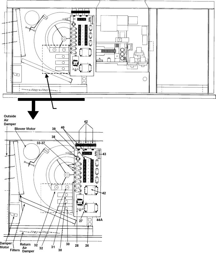
Blower Cabinet Electrical Component Location ("B" Cabinet is illustrated; control locations are the same in the larger capacity "BL" Cabinets)
See Note at the bottom of the page about building management control option.
Reference NOTE: Except where a page number is listed, see pages 8-10 for illustrations and additional information about electrical components.
Optional Downturn
Plenum Cabinet
Code |
Description |
|
P/N |
|
25 |
Fuse Holder (Fuse, see page 9) |
60241 |
||
26 |
Convenience Outlet |
96912 |
||
27A |
Blower Motor Contactor - 24V Coil |
216386 |
||
(replaces P/N 93661 and P/N 119625) |
||||
27B |
Blower Motor Starters - see P/N's on pages 27-30. |
|
||
28 |
Temperature Controller (Options AG41, AG42) |
197204 |
||
29 |
High Ambient Limit Control (Opt BN2) |
126170 |
||
30 |
Outside Air or Return Air Controller |
126170 |
||
(or P/N 197204, J/C A19ABC-24) |
||||
|
|
|||
31 |
Mixed Air Controller |
16109 |
||
32 |
Potentiometer |
|
16110 |
|
33 |
Starter Relay (replaces 105803) |
110656 |
||
34 |
Summer Winter Relay (Option BF2) - See P/N's on page 10. |
|||
35 |
RBM Relay (BG Options) - See P/N's on page 10. |
|
||
37 |
2-Speed Motor Speed Selector Relay - See |
110656 |
||
illustration in CODE 33, page 10. |
||||
38 |
Auto Reset Reverse Flow Limit |
103323 |
||
39 |
Return Air Firestat (Option BD3); See Code 4, pg 8. |
42782 |
||
40 |
Low Voltage Terminal Blocks |
144972 |
||
41 |
Low Voltage Terminal Block Adapters |
144973 |
||
|
|
115V to 24V, 20VA |
103054 |
|
|
|
115 to 24V, 40VA |
103055 |
|
|
|
208/230 to 24V, 40VA |
103497 |
|
|
Control and |
460 to 24V, 40VA |
103498 |
|
42A |
Damper |
208 to 24V, 200VA |
38634 |
|
and |
Transformers |
230/460/575 to 24V, 200VA |
39095 |
|
42B |
(See Chart on |
230/460/575 to 115V, 300VA |
105202 |
|
|
page 5.) |
208 to 115V, 500VA |
86998 |
|
|
|
230/460 to 115V, 500VA |
86997 |
|
|
|
575 to 115V, 500VA |
112641 |
|
|
|
575 to 115V, 750VA |
112642 |
|
43 |
Air Proving Switch |
|
112107 |
|
44A |
Blower Cabinet Electrical Box - std left side controls |
100092 |
||
Blower Cabinet Electricall Box - optional right side |
95486 |
|||
|
controls |
|
||
|
|
|
||
44B |
Electrical Box Cover |
100095 |
||
44C |
Electrical Box Top |
|
196648 |
|
Building Management Control NOTE: If equipped with Option D1-D4 for DDC interface to the building's computerized environmental control system, the dotted line (top illustration) indicates the location of the electrical box that houses the specially programmed Johnson Control Metasys® control unit. Box Cover is P/N 171739. Other components are listed on page 11.
Form P-RG/RP/RBL, P/N 263984R4, Page 7

Electrical Components - See location drawings on pages 6-7.
Code 1 - Electrical Box and Cover (in the
electrical compartment) Electrical Box, P/N 100108 (replaces 11965 on Model RG)
Electrical Box Cover, P/N 100109 (replaces P/N 9546 on Model RG)
Code 2 - Freezestat, J/C
#AI9AAF-2C, 25-225oF,
P/N 126170, (replaces P/N 16108)
Bulb Clamp,
P/N 100260
Grommet Clamp,
P/N 131993; Cable
Clamp, P/N 132065
Code 3 - Combustion Air Switch -
Replacement depends on date of manufacture and altitude:
For power vented models mfgd beginning 7/04, altitudes to 4000 ft, P/N 204327, setpoint 0.58 ± .05" w.c. ; altitudes above 4000 ft, order P/N 204328, setpoint .52 ± .05" w.c.
For RP Series units mfgd between 12/91 and 7/04 (except RP/RPB Models with Option AG39/40 or 1st furnace of Models HRPD/RPBL with Option AG41/42 modulating gas controls), for altitudes to 4000 ft, order replacement kit P/N 193810; for altitudes above 4000 ft, order P/N 193811.
For RP/RPB Models mfgd between 12/91 and 7/04 with Option AG39/40 and 1st furnace of Models HRPD/RPBL with Option AG41/42 gas controls, order P/N 193813 for RP(B) Sizes 125-225 and HRPD 250-400 or PN 193812 for RP(B) Sizes 250-400, HRPD 500-800, and all RPBL.
For all RP Series Models manufactured prior to 12/91 (serial No. Date Code AQL), order Replacement Pressure Switch Kit,
P/N 93033.
Codes 4 & 39 - Firestat, Honeywell #L4029E 1029, Manual reset
opens at 200°F,
P/N 42782
Firestat Gasket, P/N 121041
(used when firestat is installed
less cover)
Firestat Shield, P/N 120021
(used with discharge firestat only)
Code 6 - Discharge Sensor for Modulating Gas Valve,
P/N 48041, Maxitrol TS-121, for Options AG8 & AG9; P/N 133228, Maxitrol TS-194 for
Options AG39 & AG41
Gasket,
P/N 104138
Code 7A - Two-Stage
Ductstat, Honeywell
T678A1015,
P/N 41700
55-58°F,
Capillary
Length 5' -
Used in
Gas Control
Options
AG3, AG4,
and AG5
Bulb Holder, P/N 100260
Cable Strap, P/N 16227
Code 5 - Ignition Controllers |
|
||
Ignition Controller for Intermittent |
Ignition Controller for Intermittent |
||
Spark Pilot System without Lockout, |
Spark Pilot System with Lockout, |
||
P/N 257009 (Serial No. Code 94) |
P/N 257010 (Serial No. Code 95) |
||
To replace a |
|
To replace a |
|
previously used |
previously used |
||
recycling ignition |
ignition controllers |
||
controllers without |
with lockout |
||
lockout (Serial No. |
(Serial No. Codes |
||
Codes 62 and 66), |
63, 65 and 84), |
||
order Replacement |
order Replacement |
||
Kit, P/N 257472 |
Kit, P/N 257473 |
||
Location and Components for |
Code 7B - Ductstat Sensor and Holder |
||
Installing Discharge Sensor, |
for Code 7C Remote Ductstats |
||
Code 7A |
|
Ductstat Sensor Holder, |
|
Sheetmetal |
|
#TE6001-1, P/N 115850 |
|
|
|
||
Retaining |
|
|
|
Plate, |
|
Ductstat |
|
P/N 7727 Gasket, |
|||
|
P/N 7726 |
Sensor only, |
|
|
|
#SET A99BC-25C, P/N 115851, |
|
|
Capillary |
(part of P/N 115848 below) |
|
(Entrance |
Code 7C - Remote Ductstat Modules in |
||
|
|||
in ductwork) |
|
Gas Control Options AG15-AG20 |
|
|
|
||
Element Bracket
P/N 100260*
*Element bracket P/N 100260 is for CODE 7A, P/N 41700, manufactured by Honeywell. If using a CODE 7A, P/N 41700, manufactured by Essex Corporation, the element bracket P/N is 104156.
Leg
Cabinet
A |
B |
C |
A = Ductstat Temperature Selector Module,
J/C A350AA-1C, P/N 115848
B = Stage Adder Module, J/C S350AA-1C,
P/N 115849
C = Digital Temperature Display Module,
J/C D350AA-1C, P/N 115852
Form P-RG/RP/RBL, P/N 263984R4, Page 8
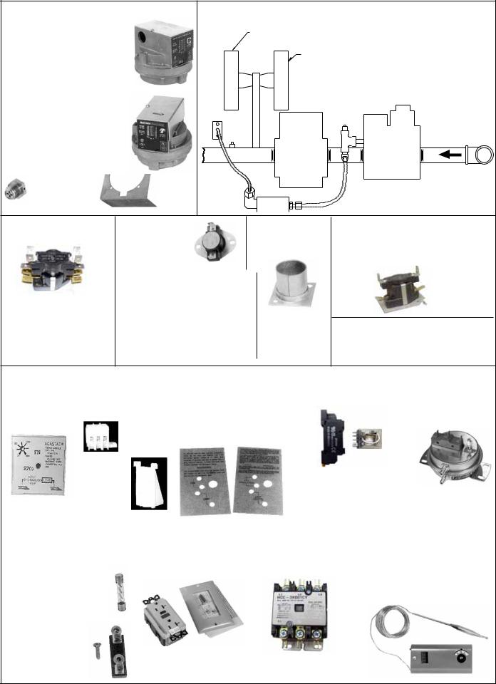
Codes 8, 9, 10 - Gas Pressure Switches
Codes 8 & 9 - Low Gas Pressure Switch, P/N 93849 (Range 1-6" w.c.); P/N
149176 (Range 6-24" w.c.)
Automatic Reset, Settings - 50% of minimum inlet gas pressure as stated on the unit rating plate
Code 10 - High Gas
Pressure Switch, P/N 93850
Manual Reset, Settings - 125% of normal manifold gas pressure as stated on the unit rating plate
Vent Limiter, |
Bracket, |
Maxitrol A1209, |
P/N |
P/N 123481 |
100261 |
Code 11 - Manifold and Control with Gas Pressure Switches used in Modulating Gas Control Options AG39, AG40, AG41, AG42
Primary Gas Flow Pressure Switch, White Label, 1.1” w.c., P/N 174809
ForAG 39, 40, 41, 42 with a solenoid actuator (mfgd
before 11/03), Backup Gas Flow Pressure Switch, Yellow Label 1.4” w.c., P/N 175985
ForAG 39, 40, 41, 42 with a gear motor (mfgd beginning 11/03), there are two gas flow pressure switches with the white label, 1.1” w.c., P/N 174809
Modulating
Valve
Carryover
Regulator
Single-Stage
Gas Valve
NOTE: Carryover regulator parts are on page 17. See Parts Form
P-VALVES for gas valves.
Code 12 - Time Delay
Relay , P/N 259780
To replace time delay relay (P/N 46233 or 259518) used on product manufactured prior to 2/2010, order replacement kit, P/N 259521.
Code 13A - |
Code 13B - Limit |
Limit Control, |
Control Shield, |
P/N 50417, |
P/N 12229 |
opens 125°F; |
|
closes 105°F |
|
Used on RG, RGB, RP, RPB Series units; for "BL" packaged systems, see page 10.
NOTE: Limit Control for RP/ HRPD with Option BU12 is P/N 196571, 140°F, red/white label
Used with Code 13A on Models RG and RGB
Code 14 - SPST Time Delay
Relay (for fan/blower control on units mfgd beginning 12/04), P/N
209164, Thermodisc I2S20-305131
For units manufactured prior to 12/04, the temperature activated fan control is no longer available. Order Replacement Kit, P/N 209184.
Code 15 - Time |
|
Codes 16 & 17; 19 |
|
Code 18 - Heat Shields (on |
|
Code 21 - Freezestat |
|
Code 22 - Dirty |
|||||
|
|
|
|
||||||||||
Delay Relay, |
|
& 20; and 40 & 41 |
|
units mfgd prior to 12/04) |
|
Relay, P/N 211411 and |
|
Filter Pressure |
|||||
T & B Agastat |
|
Terminal Block, |
|
For U.S. |
For |
|
P/N 211415 |
|
|
|
Switch, Tridelta |
||
TM1ULA, |
|
P/N 144972 |
|
|
Unit, |
Canadian |
|
|
|
|
|
AP4434, |
|
P/N 89661 |
|
|
|
|
P/N |
Unit, |
|
|
|
|
|
P/N 105507 |
|
|
|
|
|
|
|
|
|
|
|
|
|||
|
|
|
|
|
10188 |
P/N 63818 |
|
|
|
|
|
|
|
|
|
Terminal |
|
|
|
|
|
|
|
|
|
|
|
|
|
Block |
|
|
|
|
|
|
For units manufactured |
|
|
||
|
|
Adapter, |
|
|
|
|
|
|
prior to 9/2011, order |
|
Field adjustable; |
||
Used in the |
|
P/N |
|
|
|
|
|
|
a replacement kit, P/N |
|
|||
|
144973 |
|
|
|
|
|
|
263527, to replace |
|
range .17 to 5.0" w.c. |
|||
freezestat circuit. |
|
|
|
|
|
|
|
|
plus or minus .05" w.c. |
||||
|
|
|
|
|
|
|
|
|
relay. |
|
|
|
|
|
|
|
|
|
|
|
|
|
|
|
|
|
|
Code 25 - Fuse |
|
|
Code 26 - |
|
Code 27A - Motor |
|
Code 28 - Temperature |
||||||
|
|
|
|
||||||||||
and Fuseholder |
|
|
Convenience Outlet |
|
Contactor, 24V Coil, |
|
Control, J/C #A19ABC-24, |
||||||
Fuses: |
|
|
Receptacle, |
|
P/N 216386 (replaces |
|
-30 to 100°F, used in Gas |
||||||
2-1/2 Amp, P/N 201773, |
P/N 96912 |
|
P/N's 93661 and 119625) |
|
Control Option AG41 and |
||||||||
|
|
|
|
|
|
|
|
AG42 on Models RPBL and |
|||||
Bussman FNM8 |
|
|
|
|
|
|
|
|
|
|
|||
|
|
|
|
|
|
|
|
|
|
HRPD, P/N 197204 |
|||
5 Amp, P/N 201780, |
|
|
|
|
|
|
|
|
|||||
|
|
|
|
|
|
|
|
|
|
|
|||
Bussman FNM3 |
|
|
|
|
|
|
|
|
|
|
|
|
|
8 Amp, P/N 204803, |
|
|
|
|
|
|
|
|
|
|
|
||
Bussman MDL3 |
|
|
|
|
|
|
|
|
|
|
|
|
|
Fuse Holder, |
|
|
|
|
|
|
For blower motor |
|
|
|
|
||
P/N 60241 |
|
|
|
|
|
|
|
|
|
|
|||
|
|
|
|
|
|
|
starters, see page 27-30. |
|
|
|
|
||
Form P-RG/RP/RBL, P/N 263984R4, Page 9
Electrical Components (cont'd) - See location drawings on pages 6-7.
Codes 29 and 30 - High Ambient Limit Control and Outside Air or Return Air
Controller, P/N 126170
Code 31 - Mixed Air
Controller, P/N 16109
Code 32 -
Potentiometer,
P/N 16110
Codes 33 & 37 -
Blower Relay/ 2-Speed Motor, Essex 91-102006- 1300, 24V,
P/N 110656
Codes 34 & 35 - |
|
Code 38 - Reverse |
|
|
Codes 42A - Control and Damper |
|
|
|||||||||||||||
24V, DPDT, Plugin |
|
Flow Limit, #60T11- |
|
|
Transformers, 20 and 40 VA |
|
|
|||||||||||||||
Relay, P/N 211411 |
|
313154, P/N 103323 |
|
|
P/N 103054, 115/24/20VA, |
|
|
|||||||||||||||
and Socket, |
|
|
|
|
|
|
|
|
|
|
||||||||||||
|
|
|
|
|
|
|
|
Basler #BE121625-WAR |
|
|
||||||||||||
P/N 211415 |
|
|
|
|
|
|
|
|
|
|
||||||||||||
|
|
|
|
|
|
|
|
P/N 103055, 115/24/40VA, Basler |
|
|
||||||||||||
|
|
|
|
|
|
|
|
Bracket, |
|
|
|
|
||||||||||
For units manufactured prior to 9/2011, |
|
|
|
|
|
|
#BE141650-WAA |
|
|
|
|
|
||||||||||
|
|
|
|
P/N |
|
|
|
|
|
|
|
|||||||||||
order a replacement kit, P/N 263527, to |
|
|
|
|
|
|
P/N 103497, 208/230/24/40VA, Basler |
|||||||||||||||
|
|
|
18795 |
|
|
|||||||||||||||||
replace relay. |
|
|
|
|
|
|
#BE2153900 |
|
|
|
|
|
|
|||||||||
|
|
|
|
|
|
|
|
|
|
|
|
|
|
|||||||||
|
|
|
|
|
|
|
|
|
|
P/N 103498, 460/24/40VA, Basler |
|
|
||||||||||
Code 39 - See Code 4, page 8. |
|
|
|
|
|
|
|
|
|
|
||||||||||||
Codes 40 & 41 - See Codes 16 & 17, page 9. |
|
|
|
|
|
|
#BE23975001 |
|
|
|
|
|
|
|||||||||
|
|
|
|
|
|
|
|
|
|
|
|
|
|
|
|
|
|
|
|
|||
Codes 42B - Control and Damper |
|
Codes 43 - Blower Air |
|
Code 44 - Blower Cabinet Electrical Boxes |
||||||||||||||||||
Transformers, 200 and 300 VA |
|
Flow Switch, Tridelta |
|
and Cover |
|
|
|
|
|
|
||||||||||||
|
|
|
FP6605, Normally Open |
|
Cover, |
Left Side |
|
|
Optional Right |
|||||||||||||
|
|
|
Non-Adjustable, Setpoint |
|
P/N |
|
Controls Box, |
|
Side Controls |
|||||||||||||
|
|
|
.175"w.c., P/N 112107 |
|
100095 |
P/N 100092 |
|
|
Box, P/N 95486 |
|||||||||||||
|
|
|
|
|
|
|
|
|
|
|
|
|
|
|
|
|
|
|
(See |
|
|
|
|
|
|
|
|
|
|
|
|
|
|
|
|
|
|
|
|
|
Orientation |
|
|
||
|
|
|
|
|
|
|
|
|
|
|
|
|
|
|
|
|
|
Illustration |
|
|
||
P/N 105202, 575/115/300VA - Use |
|
|
|
|
|
|
|
|
|
|
|
|
|
|
|
|
on page 4) |
|
|
|||
|
|
|
|
|
|
|
|
|
|
|
|
|
|
|
|
|
|
|
|
|
||
|
on 115V furnace |
|
(Air Proving Switch, |
|
|
|
|
|
|
|
|
|
|
|
|
|
|
|||||
P/N 39095, 230/460/575-24- |
|
|
|
|
|
|
|
|
|
|
|
|
|
|
|
|||||||
|
Option BW1) |
|
|
|
|
|
|
|
|
|
|
|
|
|
|
|
|
|||||
|
200VA |
|
See page 22 for blower |
|
|
|
|
|
|
|
|
|
|
|
|
|
|
|||||
P/N 38634, 208/24/200VA |
|
|
|
|
|
|
|
|
|
|
|
|
|
|
|
|||||||
|
pitot probe. |
|
|
|
|
|
|
|
|
|
|
|
|
|
|
|
|
|||||
|
|
|
|
|
|
|
|
|
|
|
|
|
|
|
|
|
|
|
|
|||
|
Limit Controls used on Model |
|
|
|
|
Automatic |
|
|
|
|
|
|
|
|
|
|
|
|
|
|||
|
|
|
|
|
Key: (Applies to both limit tables) |
|
|
|||||||||||||||
|
Series RGBL, PGBL and RPBL |
|
|
|
|
Reset Limit |
|
"BL" Blower |
|
Furnace |
|
Furnace |
Furnace |
|
||||||||
|
mfgd beginning 1/97 (for older |
|
|
|
|
Control, TOD |
|
|
Cabinet |
|
|
|
||||||||||
|
units, see below) |
|
|
|
|
#60T11 |
|
Air Flow |
|
|
|
#1 |
|
|
#2 |
#3 |
|
|||||
|
|
|
|
|
|
|
|
|
|
|
|
|
|
|
||||||||
|
Automatic |
|
|
|
|
|
|
|
|
|
|
|
|
|
|
|
|
|
|
|
|
|
|
|
|
|
|
|
|
|
|
|
|
|
|
|
|
|
|
|
|
|
|||
|
Reset Limit |
Furnace |
|
Size 400 |
|
Sizes 500/600/800 |
|
Sizes 1050/1200 |
|
|||||||||||||
|
Control with |
#1 |
|
|
50418, 201220, 145°F |
|
50418, 201220, 145°F |
50417, 201234, 125°F |
|
|||||||||||||
|
Linear Sensor, |
|
|
148588, TOD #10HG11 |
|
|
||||||||||||||||
|
|
|
|
|
|
|
|
|
57953, 201614, 170°F |
|
|
|
|
|
||||||||
|
TOD #10HG11, |
#2 |
|
|
|
|
|
|
|
50418, 201220, 145°F |
|
|||||||||||
|
|
|
|
|
|
|
|
148588, TOD #10HG11 |
|
|||||||||||||
|
P/N 148588 |
|
|
|
|
|
|
|
|
|
|
|
|
|
|
|
|
|
|
|
|
|
#3 |
|
|
|
|
|
|
|
|
|
|
|
|
|
|
57953, 201614, 170°F |
|
||||||
|
|
|
|
|
|
|
|
|
|
|
|
|
|
|
|
|
|
|||||
|
|
|
|
|
|
|
|
|
|
|
|
|
|
|
|
|
148588, TOD #10HG11 |
|
||||
Limit Controls & Shields used |
|
|
|
|
|
|
|
|
|
|
|
|
|
|
||||||||
|
|
|
|
|
|
|
|
|
|
|
|
|
|
|
|
|||||||
|
|
|
|
|
|
|
|
|
|
|
|
|
|
|
|
|
|
|||||
on Model Series RGBL and |
|
|
|
|
|
|
|
|
|
|
|
|
|
|
|
|
|
|
|
|
||
|
|
Furnace |
Size 400 |
|
|
Sizes 500/600/800 |
|
Sizes 1050/1200 |
|
|||||||||||||
RPBL mfgd prior to 1/97 |
|
|
|
|
|
|
||||||||||||||||
|
|
|
|
|
50418, 201220, 145°F |
50418, 201220, 145°F |
|
|
|
|
||||||||||||
|
Limit Shields |
|
|
#1 |
|
50417, 201234, 125°F |
|
|||||||||||||||
|
|
|
|
|
|
|
|
12229, Limit Shield |
12229, Limit Shield |
|
|
|
|
|
||||||||
|
|
|
|
|
#2 |
|
|
|
|
|
57953, 201614, 170°F |
19080, 35675, 155°F |
|
|||||||||
|
Automatic Reset |
|
|
|
|
|
|
|
|
|
|
|
|
|
|
9704, Limit Shield |
|
|||||
|
#3 |
|
|
|
|
|
|
|
|
|
|
|
|
57953, 201614, 170°F |
|
|||||||
|
Limit Control, |
|
|
|
|
|
|
|
|
|
|
|
|
|
|
|
|
|
|
|||
|
P/N 12229 P/N 9704 TOD #60T11 |
|
|
|
|
|
|
|
|
|
|
|
|
|
|
|
|
|
|
|||
Form P-RG/RP/RBL, P/N 263984R4, Page 10
Replacement Pilot -
All Furnaces
Replacement |
|
1N, |
Pilot Kits: |
6* |
1P |
Natural Gas - |
|
4 |
P/N 110861 |
|
3 |
Propane - |
5* |
|
P/N 110862 |
|
|
*Included in the replacement
kit which covers several models of heaters; these parts are not used when replacing pilots on the heaters covered in this manual.
Code |
P/N |
Component Description |
|
1N |
61145 |
Natural gas pilot with orifice, high tension lead, flame |
|
probe (less pilot tubing and flame sensor lead) |
|||
1P |
61146 |
Propane gas pilot with orifice, high tension lead, |
|
flame probe (less pilot tubing and flame sensor lead) |
|||
2N |
63088 |
Natural gas pilot orifice only (7221) |
|
2P |
37801 |
Propane gas pilot orifice only (4209) |
|
3 |
5145 |
Pilot tubing, 22" long |
|
9664 |
Nut with breakaway ferrules (2 required) |
||
|
|||
4 |
44675 |
Sensor lead 9" long |
|
5* |
112647 |
Crimp-on, 90° Rajah terminal connector |
|
6* |
112648 |
90° Boot Terminal Protector |
Toggle Switches |
|
|
|
P/N 40277, DPDT, |
|
P/N 101900, DPDT, 3-Position |
|
3-Position Toggle |
|
Toggle Switch (replaces P/N 21826) |
|
Switch in a |
|
- Used in Option CN1 and Remote |
|
4x4 box |
|
Console |
|
(Same |
|
Options RC5, |
|
as |
|
RC6, RC7, |
|
Option |
|
RC8, RC10, |
|
CN1) |
|
RC11, RC12 |
|
|
|
|
|
|
|
|
|
P/N 39733, SPDT, |
P/N 101901, SPDT, 2-Position |
|
|
2-Position Toggle |
Toggle Switch (replaces P/N 1052) - |
|
|
Switch in |
Used in Options CN3, CN4, |
|
|
a 2x4 box |
and Remote Console |
|
|
(Same as |
Options RC3, |
|
|
Option |
RC4, RC7, |
|
|
CN3) |
RC8, RC11 |
|
|
P/N 39732, DPST,
2-Position Toggle Switch
in a 2x4 box
(Same as Option CN2)
P/N 101902, DPST,
2-Position Toggle
Switch
(replaces P/N 16816)
- Used in Options
CN2, AG3, AG8, AG9 


and Remote Console
Option RC12
P/N 39748, SPST, 2-Position Toggle Switch in a 2x4 box (Same as Option CN4)
NOTE: When replacing SPST switch with SPDT switch, make wiring connections at appropriate two terminals for switch to function properly.
Electrical Components and Sensors when the system is equipped with a specially programmed Johnson Control Metasys® Unit for Direct Digital Control interface with the building's computerized environmental control system (Options D1, D2, D3, and D4)
DDC Control Option for RGB/RPB only |
D1 |
D2 |
D3 |
D4 |
Blower Cabinet |
|
Maintains constant mixed entering air temperature |
X |
- |
X |
- |
||
|
||||||
Maintains constant discharge air temperature |
- |
X |
- |
X |
|
|
Modulating Dampers |
X |
- |
X |
- |
|
|
On/Off Dampers |
- |
X |
- |
X |
|
|
Modulating Gas Control |
X |
X |
- |
- |
|
|
Two-Stage Gas Control |
- |
- |
X |
X |
|
|
Firestat (see Code 4, page 8) |
X |
X |
X |
X |
|
|
Freezestat (see Code 2, page 8) |
X |
X |
X |
X |
Johnson Controls |
|
Air Proving Switch (see Code 43, page 10) |
X |
X |
X |
X |
||
Metasys® |
||||||
|
|
|
|
|
Component Description |
D1 |
D2 |
D3 |
D4 |
|
J/C Metasys® DDC Interface Unit, |
171138 |
171139 |
171140 |
171141 |
|
#AS-UNT121-1 |
|||||
|
|
|
|
||
EMI Filter, Corcom #3VK1 |
|
171738 |
|
||
RBM Relay (2 on D1&2; 3 on D3&4) |
Replacement Kit for each, P/N 263527 |
||||
Fuse, 2.5 amp |
|
61542 |
|
||
Fuseholder, Buss HTB-481 |
|
60241 |
|
||
Duct Probe Temperature Sensor, J/C |
|
171135 |
|
||
#TE-631 1P-1, |
|
|
|||
|
|
|
|
||
Remote Setpoint Selector, |
|
175646 |
|
||
J/C #TE-6411S-2010 |
|
|
|||
|
|
|
|
||
Outdoor Temperature Sensor, |
|
171137 |
|
||
J/C #TE-631 3P-1 |
|
|
|||
|
|
|
|
||
SPDT Switch in 2x4 Box (see above) |
|
(2) 39733 |
|
||
DDC Damper Interface Module, |
171134 |
-- |
171134 |
-- |
|
H/W Q7230A (see Code 393, pg 23) |
|||||
DDC Gas Control Interface Module |
134170 |
-- |
-- |
||
(see photo right) |
|||||
|
|
|
|
||
direct digital control unit
DDC Gas Control Interface
Module in Options D1 and
D2, P/N 134170
Form P-RG/RP/RBL, P/N 263984R4, Page 11
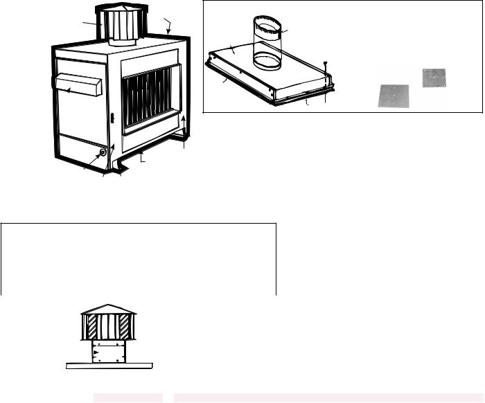
RG Cabinet and Flue Box Parts - Same parts apply to RG duct furnaces in packaged Model Series RGB and Series RGBL (Quantites listed are per furnace section.)
Basic Exterior |
|
|
Parts for |
72 |
67 |
Model RG |
|
|
|
|
|
|
|
62 |
|
63 |
61 |
|
|
|
|
63B,C,D |
|
Flue Collection Box for Basic Model RG Furnace
55 |
Flue Restrictors - Codes 56 & 81 |
|
See Codes 56 & 81 below for type |
||
51 |
and size. For application by unit size, |
|
|
see Code 56 or 81 in the table below. |
|
53 |
Type S |
|
Type D |
||
|
||
|
52 |
|
57 |
|
68 |
77 |
|
68B,C |
58 |
|
60 |
||
75 |
Codes 56 and 81 - Flue Restrictors by Type & Size


 ® Label, P/N 196689
Gray Sealant (3M 900 Duct Sealer Fast Bond), P/N 100117
Cabinet Connector & Filler Parts for Multiple Furnaces - Model RGBL
RGBL Size |
400 |
500/600 |
700 |
800 |
1050 |
1200 |
|
Top Filler |
-- |
|
(1) 105631 |
|
(2)105631 |
||
Side Filler |
-- |
|
(2 )105632 |
|
(4)105632 |
||
Top & Btm Duct |
-- |
(2) |
|
(2) |
(2) |
(2) |
(2) |
Connector |
106338 |
|
106339 |
106340 |
106339 |
106340 |
|
|
|
||||||
Side Duct Connector |
-- |
|
|
(2)106395 |
|
(4)106395 |
|
P/N |
Type |
Size |
P/N |
Type |
Size |
15584 |
S |
6-7/16 x 6-7/16 |
89209 |
D |
6-3/8 x 6-3/8 |
86440 |
D |
5-5/8 x 5-5/8 |
89210 |
S |
3 x 7-1/2 |
86454 |
D |
7 x 7 |
89211 |
S |
4-3/4 x 4-7/16 |
86479 |
S |
1-3/4 x 5-3/4 |
89212 |
D |
7-3/4 x 7-3/4 |
86485 |
D |
6-1/4 x 6-1/4 |
89213 |
S |
8-5/8 x 8-5/8 |
86488 |
S |
8 x 8 |
136738 |
D |
3-3/8 x 3-3/8 |
86490 |
S |
4-7/8 x 11-3/4 |
136739 |
S |
5 x 1-1/2 |
86492 |
S |
4-1/4 x 4-1/4 |
136740 |
D |
5-1/8 x 5-1/8 |
86493 |
D |
6 x 6 |
136741 |
D |
4-13/16 x 4-13/16 |
86495 |
S |
8-1/2 x 8-1/2 |
136742 |
D |
4-1/2 x 4-1/2 |
86496 |
S |
4-3/4 x 4-3/4 |
136743 |
D |
4-5/8 x 4-5/8 |
86497 |
D |
7-3/8 x 7-3/8 |
136744 |
D |
4-1/4 x 4-1/4 |
86498 |
S |
9 x 9 |
136745 |
D |
6-3/8 x 6-3/8 |
89205 |
D |
5-3/4 x 5-3/4 |
136746 |
D |
6-1/8 x 6-1/8 |
89206 |
S |
3-5/8 x 7-1/2 |
136747 |
D |
9-1/8 x 9-1/8 |
89208 |
D |
6-7/8 x 6-7/8 |
|
|
|
Code 73 - |
|
|
|
|
|
|
|
|
|
|
|
|
|
|
|
|
|
|
|
|
|
|
|
|
|
|
|||||
|
|
|
|
|
|
|
|
|
|
|
|
|
Furnace |
|
|
|
73 - Extension |
|
|
|
|
||||||||||
Vent Cap |
|
|
|
|
|
|
|
|
|
|
|
|
|
|
|
|
|
|
|
|
|
|
|
|
|
|
|
|
|
||
|
|
|
|
|
|
|
|
|
|
|
|
Model |
Sizes |
|
Series |
|
|
|
Height |
|
P/N |
|
|
|
|
||||||
Extension |
|
|
|
|
|
|
|
|
|
|
|
|
|
|
|
|
|
|
|
|
|
|
|
|
|
|
|
|
|
||
|
|
|
|
|
|
|
|
|
|
|
|
RG, HRG |
300, 350, 400 |
Prior to Series 8 & Series 8 |
|
12" |
20524 |
|
|
|
|
||||||||||
|
73 |
|
|
|
|
|
|
|
|
|
|
|
|
|
CRG, |
350 |
|
Prior to Series 8 & Series 8 |
|
12" |
20524 |
|
|
|
|
||||||
|
|
|
|
|
|
|
|
|
|
|
|
|
|
HCRG |
400 |
|
Series 8* |
|
|
|
*12" |
20524 |
|
|
|
|
|||||
|
|
|
|
|
|
|
|
|
|
|
|
|
|
|
|
|
|
|
|
||||||||||||
|
|
|
|
|
|
|
|
|
|
|
|
|
|
|
|
|
|
|
|
|
|
|
|
|
|
|
|
|
|
|
|
|
|
|
|
|
|
|
|
|
|
|
|
|
|
|
*Prior to Series 8, height was 7-1/4"; part is no longer available. |
|
|
|
|
|
|
||||||||||
|
|
|
|
|
|
|
|
|
|
|
|
|
|
|
|
|
|
|
|
|
|
|
|
|
|
|
|
|
|
|
|
|
|
|
|
|
|
|
|
|
|
|
|
|
|
|
|
|
|
|
|
|
|
|
|
|
|
|
|
|
|
|
|
|
|
|
|
|
|
|
|
|
|
|
|
|
RGBL Sizes |
Qty |
|
|
|
|
|
|
|
|
|
|
|
500 |
|
600 |
700, |
400, 800, |
|
Code |
Description |
|
|
|
|
|
|
|
|
|
|
|
|
|
|
|
|
|
|
|
|
|
1050 |
1200 |
|||||||
|
|
|
|
|
|
|
|
|
|
|
|
|
|
|
|
|
|
|
|
|
|
|
|
||||||||
|
|
|
|
|
|
|
|
|
|
|
RG/RGB Sizes |
|
75 |
|
100 |
125 |
150 |
175 |
200 |
|
225 |
|
250 |
|
300 |
350 |
400 |
||||
51 |
Flue Collection Box |
|
|
|
|
|
|
|
|
RG, HRG - All |
1 |
136749 |
|
136750 |
86437 |
136751 |
136752 |
136753 |
136754 |
|
136755 |
136756 |
136757 |
86470 |
|||||||
Assembly |
|
|
|
|
|
CRG, HCRG - All |
1 |
86476 |
|
86478 |
86480 |
-- |
86482 |
-- |
|
89207 |
|
86484 |
|
86486 |
86487 |
86489 |
|||||||||
|
|
|
|
|
|
|
|
|
|||||||||||||||||||||||
52 |
Collection Box Side Gasket Strip |
2 |
|
|
|
|
|
|
|
62933 |
|
|
|
|
|
|
|
||||||||||||||
53 |
Collection Box Front and Rear Gasket Strip |
2 |
62921 |
62922 |
62924 |
62926 |
|
62928 |
62930 |
62932 |
|||||||||||||||||||||
55 |
Flue Collar Assembly |
|
|
|
|
|
|
|
|
|
1 |
103786 |
|
|
103788 |
|
|
|
12014 |
|
|
|
|
12015 |
|
||||||
56 |
Flue Restrictor - See |
|
RG, HRG Series 8** |
1 |
136738 |
|
136739 |
86440 |
136740 |
136741 |
86493 |
|
136742 |
|
86493 |
|
86454 |
-- |
-- |
||||||||||||
Type and Size in chart |
|
|
|
|
|
|
|
|
|
|
|
|
|
|
|
|
|
|
|
|
|
|
|
|
|
|
|
||||
|
|
|
|
|
CRG, HCRG - All |
1 |
86492 |
|
86479 |
89205 |
-- |
89206 |
-- |
|
89208 |
|
89209 |
|
89210 |
86488 |
86490 |
||||||||||
|
above. |
|
|
|
|
|
|
|
|
||||||||||||||||||||||
57 |
Bottom Front & Rear Panel (Sizes 75-100 |
2 |
103644 |
100037 |
100038 |
100039 |
|
100040 |
100041 |
100042 |
|||||||||||||||||||||
include insulation) |
|
|
|
|
|
|
|
|
|
|
|||||||||||||||||||||
58 |
Heater Bottom Pan |
|
|
|
|
|
|
|
|
|
Aluminized |
1 |
|
100000 |
|
|
100001 |
100002 |
|
100003 |
100004 |
100005 |
|||||||||
|
|
|
|
|
|
|
|
409 Stainless |
1 |
104925 |
|
104926 |
104925 |
104926 |
104927 |
|
104928 |
104929 |
104930 |
||||||||||||
|
|
|
|
|
|
|
|
|
|
|
|
|
|
||||||||||||||||||
60 |
Heater Mounting Rail |
|
|
|
|
|
|
|
|
|
|
2 |
|
|
|
|
|
|
|
100126 |
|
|
|
|
|
|
|
||||
61 |
Top Front and Rear Panel (Sizes 75-100 |
2 |
103645 |
100030 |
100031 |
100032 |
|
100033 |
100034 |
100035 |
|||||||||||||||||||||
include insulation) |
|
|
|
|
|
|
|
|
|
|
|||||||||||||||||||||
|
|
|
|
|
|
|
|
|
|
|
|
|
|
|
|
|
|
|
|
|
|
|
|
|
|
|
|||||
62 |
Casing Top Assembly (include insulation) |
1 |
103652 |
103653 |
103654 |
103655 |
|
103656 |
*103657 |
103658 |
103659 |
||||||||||||||||||||
63 |
Heater Upper Left Side Panel Assembly |
1 |
|
103646 |
|
|
|
|
|
|
103647 |
|
|
|
|
||||||||||||||||
(includes Codes 63A, 63B, 63C, & 63D) |
|
|
|
|
|
|
|
|
|
|
|
||||||||||||||||||||
|
|
|
|
|
|
|
|
|
|
|
|
|
|
|
|
|
|
||||||||||||||
63A |
Heater Left Side Panel |
|
|
|
|
|
|
|
|
|
1 |
|
|
|
|
|
|
|
100116 |
|
|
|
|
|
|
|
|||||
63B |
Left Side Combustion Air Inlet Screen |
1 |
-- |
|
-- |
-- |
|
|
|
|
|
148396 |
|
|
|
|
|||||||||||||||
63C |
Left & Right Side Combustion Air Inlet Shield |
1 |
|
|
|
|
|
|
|
110697 |
|
|
|
|
|
|
|
||||||||||||||
63D |
Left & Right Side Combustion Air Inlet Angle |
1 |
|
12649 |
|
|
|
|
|
|
10850 |
|
|
|
|
||||||||||||||||
67 |
Heater Right Side Panel Assembly (includes |
1 |
|
103648 |
|
|
|
|
|
|
103649 |
|
|
|
|
||||||||||||||||
Codes 67A-C,63C-D) |
|
|
|
|
|
|
|
|
|
|
|
|
|
|
|
|
|
|
|
|
|||||||||||
67A |
Heater Right Side Panel |
|
|
|
|
|
|
|
|
|
1 |
|
|
|
|
|
|
|
100111 |
|
|
|
|
|
|
|
|||||
67B |
Right Side Combustion Air Inlet Screen |
1 |
-- |
|
-- |
-- |
|
|
|
|
|
148396 |
|
|
|
|
|||||||||||||||
67C |
Heater Right Side Panel Handle |
1 |
|
|
|
|
|
|
|
100112 |
|
|
|
|
|
|
|
||||||||||||||
Form P-RG/RP/RBL, P/N 263984R4, Page 12

Code |
Description |
|
RGBL Sizes |
|
|
||
|
|
|
RG Sizes |
68 |
Heater Bttm Left Side |
|
Natural Gas |
Assembly (includes |
|
||
|
|
||
68A |
68A & 68B as listed) |
Panel |
Propane |
Heater Bottom Left Side |
|
||
68B |
Vinyl Grommet |
|
|
72Vent Cap
73Vent Cap Extension
74Left Rear Heater Leg
75Left Front Heater Leg
76Right Rear Heater Leg
77Right Front Heater Leg
78Baffle
79Top Seal Brace
80Hanger Angle
"Z" Baffle w/optional |
RG, HRG Series 8** |
81 extended stack (Opt |
CRG, HCRG - All |
ZZ) - See chart pg 12. |
Qty |
|
|
|
|
|
|
|
|
|
500 |
600 |
700, |
400, 800, |
|
|
|
|
|
|
|
|
|
1050 |
1200 |
|||
|
|
|
|
|
|
|
|
|
|
|
|||
|
|
|
|
|
|
|
|
|
|
|
|
||
|
75 |
100 |
125 |
|
150 |
175 |
200 |
225 |
|
250 |
300 |
350 |
400 |
1 |
|
|
100298 |
|
(includes 68B P/N 102607) |
|
|
|
100299 |
(includes |
68B P/N |
||
|
|
|
|
|
|
|
15021) |
|
|||||
1 |
|
|
|
|
100298 (includes 68B P/N 102607) |
|
|
||||||
|
|
|
|
|
|
|
|||||||
1 |
|
|
|
|
|
|
100125 |
|
|
|
|
|
|
1 |
|
|
|
|
|
102607, #1020-K, 1/2" |
|
|
|
|
|||
-- |
-- |
-- |
|
-- |
-- |
-- |
-- |
|
-- |
15021, #1020, 3/4" |
|||
|
|
|
|||||||||||
1 |
|
|
|
|
|
|
|
|
|
|
*61875 |
61875, 12" |
|
110053, 6" |
|
61857, 8" |
|
61866, 10" |
|
||||||||
|
|
|
|
|
|
See Table on page 12. |
|
|
|
|
|||
1 |
100009 |
|
|
|
|
|
100013 |
|
|
|
|
|
|
1 |
100007 |
|
|
|
|
|
100011 |
|
|
|
|
|
|
1 |
100008 |
100008 |
100012 |
|
100012 |
100012 |
100012 |
100012 |
|
100012 |
100012 |
100012 |
100012 |
1 |
100006 |
100006 |
100010 |
|
100010 |
100010 |
100010 |
100010 |
|
100010 |
100010 |
100010 |
100010 |
1 |
|
|
|
|
|
|
10921 |
|
|
|
|
|
|
2 |
100162 |
100163 |
|
100164 |
100165 |
|
100166 |
100167 |
100168 |
||||
2 |
|
|
|
|
|
|
11012 |
|
|
|
|
|
|
1 |
136743 |
136744 |
136745 |
|
136746 |
86493 |
89212 |
15596 |
|
86454 |
136747 |
86495 |
86495 |
1 |
86496 |
89211 |
15584 |
|
-- |
86485 |
-- |
86488 |
|
89212 |
86497 |
86498 |
89213 |
|
|
|
|
|
|
|
|
|
|
|
|
|
|
*Model CRG300 - Casing Top Assembly, P/N 103656 and Vent cap (10"), P/N 61866
**These replacement parts for Models RG, HRG manufactured prior to Series 8 (5/95) are no longer available; see page 3.
Indoor
Packaged
Model
PGBL
Furnace
Cabinet
and Venter
Box Parts
Venter Components

(Codes 98-104)
112
113
115 

Venter Box (Codes 90-94)
 110
110
118
111
|
117 |
|
107 |
Indoor Model |
|
PGBL800 with two |
||
|
||
|
furnace sections |
|
108 |
and a "BL" blower |
|
cabinet |
Code |
Description |
400 |
800 |
|
1200 |
||
90 |
Venter Box Bottom |
150971 |
149851 |
|
149852 |
||
91 |
Venter Box Cover |
149853 |
149854 |
|
149855 |
||
92 |
Venter Cover End |
150974 |
149856 |
||||
93 |
Venter Gasket |
-- |
149857 |
||||
94 |
Venter Baffle |
-- |
150973 |
||||
95 |
Flow Sensing Probe |
151559 |
|
|
|||
96 |
Sensor Bracket |
123910 |
|
|
|||
97 |
Silicone Tubing |
151564, 17" Red Tubing |
147905, 9" Red Tubing |
||||
98 |
Venter Housing |
151560 |
151343 |
||||
|
|
115V/1Ph |
87434 Fasco #7162-1775 |
16074 A. O. Smith #199 |
|||
|
|
208V/1Ph |
30249 Fasco #7162-0186 |
16074 A. O. Smith #199 |
|||
99 |
Venter |
230V/1Ph |
29571 Fasco #7162-0158 |
16074 A. O. Smith #199 |
|||
208V/3Ph |
30249 Fasco #7162-0186 |
16075 Century 8-125439 |
|||||
Motor |
|||||||
230V/3Ph |
29571 Fasco #7162-0158 |
16075 Century 8-125439 |
|||||
|
|
||||||
|
|
460V/3Ph |
87434 Fasco #7162-1775 |
16075 Century 8-125439 |
|||
|
|
575V/3Ph |
87434 Fasco #7162-1775 |
16074 A. O. Smith #199 |
|||
100 |
Capacitor |
|
163894, Aerovox |
2857-MF-B |
|
||
101 |
|
|
29792 Torrington |
8735 Torrington |
|||
Venter Wheel |
#AA729-419-7-29/32- |
||||||
#AA408228, 1-5/16" |
|||||||
|
|
|
4-17/32 |
||||
|
|
|
|
||||
102 |
Venter Fan |
29793 |
|
|
|||
103 |
Venter Junction Box |
29595 |
|
|
|||
104 |
Junction Box Cover |
29596 |
|
|
|||
105 |
Flue Collection |
149859 |
(2)149859 |
|
(3)149859 |
||
Box Assy (interior) |
|
||||||
106 |
Flue Collar Assy |
150326 |
(2)150326 |
|
(3)150326 |
||
(interior) |
|
|
|||||
Code |
Description |
|
400 |
800 |
1200 |
|
107 |
Bottom Front & Rear Panel |
(2)100042 |
(4)100042 |
(6)100042 |
||
108 |
Furnace |
|
Aluminized |
100005 |
(2)100005 |
(3)100005 |
Bottom Pan |
|
409 Stainless |
104930 |
(2)104930 |
(2)104930 |
|
109 |
Heater Mounting Rail |
(2)100126 |
(4)100126 |
(6)100126 |
||
110 |
Casing Top Assembly |
100050 |
(2)100050 |
(3)100050 |
||
(includes insulation) |
||||||
111 |
Right Side Panel Assembly |
103649 |
(2)103649 |
(3)103649 |
||
(includes Codes 111A-B) |
||||||
111A |
Heater Right Side Panel |
100111 |
(2)100111 |
(3)100111 |
||
111B |
Right Side Panel Handle |
100112 |
(2)100112 |
(3)100112 |
||
112 |
Heater Left Side Assembly |
103647 |
(2)103647 |
(3)103647 |
||
(includes Codes 112A-D) |
||||||
112A |
Heater Left Side Panel |
100116 |
(2)100116 |
(3)100116 |
||
112B |
Cmbstn Air Inlet Screen |
148396 |
(2)148396 |
(3)148396 |
||
112C |
Cmbstn Air Inlet Shield |
110697 |
(2)110697 |
(3)110697 |
||
112D |
Cmbstn Air Inlet Angle |
10850 |
(2)10850 |
(3)10850 |
||
113 |
Bottom Left Side Panel |
100299 |
(2)100299 |
(3)100299 |
||
114 |
Left Rear Heater Leg |
100013 |
(2)100013 |
(3)100013 |
||
115 |
Left Front Heater Leg |
100011 |
(2)100011 |
(3)100011 |
||
116 |
Right Rear Heater Leg |
100012 |
(2)100012 |
(3)100012 |
||
117 |
Right Front Heater Leg |
100010 |
(2)100010 |
(3)100010 |
||
118 |
Top Front & Top Rear |
(2)100035 |
(4)100035 |
(6)100035 |
||
119 |
Baffle |
|
10921 |
(2)10921 |
(3)10921 |
|
120 |
Top Seal Brace |
(2)100168 |
(4)100168 |
(6)100168 |
||
121A |
Top/Btm Ht Exch Connector |
-- |
(2)106340 |
(4)106340 |
||
121B |
Side Heat Exch Connector |
-- |
(2)106395 |
(4)106395 |
||
Form P-RG/RP/RBL, P/N 263984R4, Page 13

Model RP Cabinet and Collection Box Parts - Same parts apply to RP duct furnaces in packaged Model Series HRPD, RPB, RPBL, & RPDBL (Quantities listed are per furnace section.)
Basic Exterior Parts for Model RP
Furnace |
156 |
|
155 |
160 |
154 |
|
161 |
159B,C,D |
|
|
159 |
|
151 |
157/158 |
|
165 |
|
152 |
|
|
|
|
157B/C |
163 |
153 |


 ® Label, P/N 196689
Gray Sealant (3M 900 Duct Sealer Fast
Bond), P/N 100117
Code 168 - Vertical Vent Kit,
P/N 45021 (Same as Option CC3)
|
5” Vent Cap, |
|
P/N 110052 |
|
5” dia. Vent Pipe |
4 ft |
Support angles |
(1.2M) |
for flue pipe. |
|
Recommended |
|
type is 1/2”x1/2”, |
|
20 gauge. |
5” dia. |
|
90° Elbow |
|
18” (457mm) |
|
straight pipe |
|
Oval Adapter Assy, |
|
P/N 103025, and |
|
Seal Plate, |
|
P/N 43446 |
|
Combustion Air Intake
NOTES: Support angles and all piping are field supplied. One kit for each furance section.
Cabinet Connector & Filler Parts for Multiple Furnaces - Models HRPD & RPBL
HRPD Size |
250 |
300/350 |
400 |
|
500/600 |
700 |
|
800 |
|
- |
- |
RPBL Size |
- |
- |
400 |
|
500/600 |
700 |
|
800 |
|
1050 |
1200 |
Top Filler |
111092 |
111093 |
111094 |
105629 |
105630 |
105631 |
|
(2) |
(2) |
||
|
105630 |
105631 |
|||||||||
Gasket |
(2) |
(2) |
(2) |
|
(2) |
(2) |
|
(2) |
|
(4) |
(4) |
103605 |
103606 |
103607 |
103608 |
103609 |
103610 |
|
103609 |
103610 |
|||
|
|
||||||||||
Side Filler |
|
(2) 105632 |
|
|
(4) 105632 |
||||||
Top & Btm Duct |
(2) |
(2) |
(2) |
|
|
|
(2) 106338 |
|
|
||
Connector |
107427 |
107428 |
107429 |
|
|
|
|
||||
|
|
|
|
|
|
|
|||||
Side Duct |
|
|
(2) |
106395 |
|
|
|
|
(4) 106395 |
||
Connector |
|
|
|
|
|
|
|||||
|
|
|
|
|
|
|
|
|
|
|
|
Flue Collection Box and Venter for single furnace RP/RPB Series units without Opt AG 39 or 40, and multiple furnace units (Model
HRPD and RPBL) without Option AG 41 or 42 and 2nd and 3rd furnaces on units with Option 41 or 42.
133
|
|
|
|
|
|
130 |
|
|
|
|
|
|
|
132 |
131 |
|
|
|
|
|
|
|
|
150A |
|
134 |
|
|
146 |
|
|
150B |
|
|
|
|
147A/B |
||
|
|
|
|
|
|
||
|
|
143 - Gasket |
144 |
145 |
|
147 |
|
|
|
(142 - Cover - |
|
149 |
|
||
|
|
|
|
|
|
||
|
|
not illustrated) |
|
|
148 |
|
|
|
|
|
|
|
|
|
|
|
|
|
|
|
125-300 Inlet Ring |
|
|
|
|
|
|
|
400 - Mounting Plate |
|
|
|
|
.056 |
|
|
|
.306 |
|
|
|
|
|
|
|
|
|
Inlet Ring to Wheel
measurement - Sizes 125-350 


 Mounting Plate to Wheel measurement - Size 400
Options AG 39, 40, 41 or 42 (1st furnace only w/Opt AG 41 & 42)
|
|
|
150B |
Assembly with Gear Motor and Venter |
|
|
|
144 |
|
130 |
|
|
|
|
|
150A |
|
145 Restrictor (Sizes 125-250) |
|
|
|
|
145 Inlet Ring (Sizes 300 and 400) |
|
|
133 |
|
|
|
|
|
|
|
|
|
135 |
139 |
|
148 |
|
(Size 125) |
|
|
147A/B |
|
|
|
|
|
135 |
|
|
|
146 |
(Sizes 150-400) |
|
136 |
|
147 |
Flue Duct |
|
137 |
||
|
|
|
||
Assembly with |
|
|
Terminal Block |
138 |
Gear Motor and |
Flue Duct 139 |
NOTE: AG 39 and 40 apply to RP series models with one furnace. AG 41 and |
||
Flue Collection |
view right) |
42 apply to models with more than one furnace (HRPD, RPBL). Flue duct and |
||
|
(see detail |
|
|
|
Box |
|
gear motor parts shown here apply to the first furnace section only. |
||
Form P-RG/RP/RBL, P/N 263984R4, Page 14
 Loading...