


Model DFC
Direct-Fired, Vertical/Horizontal,
Indoor/Outdoor, Packaged,
Makeup Air Heating and Air
Conditioning System
|
|
|
|
|
Y |
PR |
O |
|
|
|
|
|
|||
|
|
|
|
C |
|
|
|
C |
|
|
|
|
|||
|
|
N |
|
|
|
|
|
|
|
|
|
|
|||
|
E |
|
|
ER |
|
|
|
E |
|
|
|
||||
|
G |
|
|
|
V |
|
G |
E |
|
|
S |
||||
|
|
|
N |
|
|
|
|
|
|
||||||
A |
|
O |
|
|
|
|
|
|
T |
|
|
||||
|
|
|
|
|
|
|
N |
|
|
|
|||||
|
C |
|
|
|
|
|
|
|
|
|
|
|
|
P |
|
RCQSQ |
S |
||||||||||||||
C |
|
|
|
|
|
|
|
|
|
|
|
|
|
|
U |
U |
|
|
|
|
|
|
|
|
|
|
|
|
|
|
T |
S |
|
|
|
|
|
|
|
|
|
|
|
|
|
|
- |
T |
|
|
|
|
|
|
|
|
|
|
|
|
|
|
R |
O |
|
|
|
|
|
|
|
|
|
|
|
|
|
|
A |
M |
|
|
|
|
|
|
|
|
|
|
|
|
|
|
T |
E |
|
|
|
|
|
|
|
|
|
|
EM |
|
|
|
|
|
|
U |
|
|
|
|
|
|
|
|
Y |
||||
|
|
|
|
|
|
|
T |
|
|
|
|||||
P |
|
A |
|
|
|
|
|
|
T |
||||||
|
R |
|
|
LITYSYS |
|
|
|
|
|||||||
|
|
|
|
|
|
|
|
|
|
|
N |
|
|||
|
O |
|
|
|
|
|
|
|
|
A |
|
|
|||
|
|
|
|
|
|
|
|
R |
|
|
|
||||
|
|
|
D |
|
|
|
|
|
R |
|
|
|
|
||
|
|
|
|
UCT WA |
|
|
|
|
|
||||||
ANSI Z83.18a-2001 CSA 3.7B-2002
ANSI Z83.4B-2002
Table of Contents |
|
Model DFC |
|
DESCRIPTION............................................................................................... |
2 |
STANDARD FEATURES................................................................................ |
3 |
OPTIONAL FEATURES - Factory Installed......................................... |
3 |
OPTIONAL FEATURES - Field Installed............................................... |
4 |
TECHNICAL DATA TABLE............................................................................. |
4 |
MODEL SIZE SELECTION............................................................................ |
4 |
UNIT CONFIGURATION OPTIONS............................................................... |
5 |
SELECTION GUIDE FOR DIRECT-FIRED MAKEUP AIR............................ |
7 |
DIMENSIONS................................................................................................. |
8 |
BRAKE HORSEPOWER TABLE.................................................................. |
18 |
PERFORMANCE TABLE............................................................................. |
20 |
FILTER TABLE............................................................................................. |
22 |
STATIC PRESSURE DROP TABLE............................................................. |
22 |
WEIGHT TABLE........................................................................................... |
23 |
AMPERAGE SPECIFICATIONS.................................................................. |
24 |
SAMPLE SPECIFICATION.......................................................................... |
25 |
REZNOR® PRODUCT LIMITED WARRANTY............................................. |
26 |
IMPORTANT: Specifications are subject to change without notice. This guide is intended to provide specifications and technical information only.
This guide is not intended to be an instruction manual. When installing HVAC Equipment, you must check and conform to all local and national building codes. Improper installation of HVAC Equipment could be dangerous. Consult manufacturer’s installation manual for instructions and important warnings.
In keeping with our policy of continuous product improvement, we reserve the right to alter, at any time, the design, construction, dimensions, weights, etc., of equipment information shown here.
Page Number _______ of ______
Model DFC
INDOOR/OUTDOOR HORIZONTAL AND VERTICAL DIRECT-FIRED MAKEUP AIR SYSTEM
DESCRIPTION |
The Reznor Model DFC Series units are direct-fired/makeup and space heaters designed for either indoor or |
|
outdoor installation. Model DFCH is horizontally arranged. Model DFCV is a vertical cabinet. Units can be con- |
|
figured for floor mount, outdoor pad mount, rooftop or suspended installation. Model DFC systems are available |
|
to operate on either natural gas or propane. |
|
Maximum heating capacity is 12,830 MBH. Maximum air handling capacity is 90,000 CFM. The DFC Series |
|
provides discharge air at a maximum temperature rise of 120°F. |
|
The gas manifold has stainless steel mixing plates and offers a 30:1 turndown ratio. There is also a solid state |
|
flame monitoring system and a burner observation port. |
|
The AMCA-rated forward curved DWDI centrifugal blower (Class I or Class II) has a polished steel shaft with |
|
rust inhibitor. Backward inclined and air foil fans are also available. Heavy duty industrial bearings are standard. |
|
Adjustable V-belt drives are used on motors through 5 HP. Fixed drives are used on motors 7.5 HP and larger. |
|
Several options are available for internal and external vibration isolation including 1” or 2” deflection spring |
|
hangers and rubber-in-shear isolation. |
|
The cabinet is constructed of 18, 16 or 14 gauge Galvaneal steel casing with rust-resistant gray enamel paint |
|
finish on a welded structural or formed channel base frame. The 1” or 2” thick, high density insulation is glued |
|
and pinned to the inside cabinet walls. Cabinets can be single wall, solid double wall (for cleaning) or with a |
|
perforated inner wall liner (for sound attenuation). Outdoor units larger than 218 have a sloped roof. Service |
|
platform is available for easy access to controls and gas train. |
|
Vertical units can be mounted on the floor, suspended or mounted on a 3’or 5’stand. Service platforms are also |
|
available for vertical or horizontal units for a convenient place to stand when working in the controls section. |
|
Service platform available for filter cabinet access for horizontal units. |
|
Model DFCH (horizontal configuration) can be arranged for vertical up, vertical down or horizontal supply air |
|
discharge. Model DFCV (vertical configuration) can also be arranged for vertical up, vertical down or horizontal |
|
supply air discharge. |
|
Standard configuration is for 100% outside air. An optional return air plenum (return air bypasses burner) is |
|
available for recirculating up to 80% return air (available in U.S. only). Inlet air weather hoods have an ex- |
|
panded metal screen with 2” filters available. Motorized two-position inlet and discharge dampers have a two- |
|
position spring return and end switch. |
|
Modules available for filter cabinets, evaporative cooling, return air plenum, DX or chilled water cooling coils; |
|
as well as steam, hot water or glycol heating coils. |
|
Electrical controls include electronic flame safeguard relay manual reset; high and low airflow pressure switch- |
|
es; motor starter with overload protection; control panel service switch; and terminal connections for exhaust |
|
interlock. |
|
The discharge air temperature control can be used with or without a room override connected to room thermo- |
|
stat. Space temperature control can also be selected. Other temperature control options include night setback, |
|
freeze protection and inlet air control which shuts down the burner when outside air exceeds temperature set- |
|
ting. Standard features include flame rod ignition system with optional dual flame rods and UV flame supervi- |
|
sion. |
|
NEMA4 control panel available unit mounted or remote enclosure. Explosion resistant panels also available. |
|
Units provided with ETL (for installation in the United States) or ETLC (for installation in Canada) rating plate. |
|
Manifolds are available to meet ANSI, FM (Factory Mutual), IRI or FM/IRI standards. |
|
All units are factory wired, piped and test fired. |
Form RZ-S-DFC Page 2

STANDARD FEATURES
OPTIONAL FEATURES -
Factory Installed
Page Number _______ of ______
●● ETL (United States) or ETLC (Canada) rating plate
●● Class I Blower (Sizes 127 - 218); Class II Blower (Sizes 222 - 236)
●● Natural gas or propane operation
●● 208/3/60 Supply voltage
●● Cabinet
▬▬Welded structural or formed channel base frame ▬▬Hinged access doors
▬▬Conveniently located lifting lugs
▬▬Heavy steel casing (18 gauge) with rust resistant gray enamel finish
▬▬One-inch thick, 1.5 lb. density, neoprene-coated fiberglass insulation pinned and glued to inside cabinet walls
▬▬Sloped roof on outdoor units on sizes 218 and larger
●● Flame rod ignition system
●● Left hand or right hand side controls
●● 100% outside makeup air with constant supply volume
●● Blower/Motor
▬▬AMCA-rated forward curve DWDI centrifugal blower ▬▬Polished steel shaft with rust inhibitor
▬▬Maximum allowable operating speed set to 75% of first critical speed
▬▬ODP motor, 1800 RPM, T frame, 1.15 service factor mounted on adjustable base
▬▬Drives designed for 150% of motor brake horsepower
▬▬Adjustable V-belt drives on 5 hp motors ▬▬Fixed drives on motors 7.5 hp and larger
●● Class II Blower
●● Gas manifold to meet ANSI, FM, IRI or FM/IRI Standards ●● Manifold arrangements from 700 to 12,830 MBH
●● Gas pressure gauge on manifold
●● 230/3/60, 460/3/60 or 575/3/60 Supply voltage
●● Ignition system
▬▬Dual flame rod ▬▬UV flame supervision
●● Remote reset button for flame safeguard system
●● Gas pressure safety switch
▬▬High gas pressure safety switch (manual reset) ▬▬Low gas pressure safety switch (manual reset)
▬▬Single body high and low gas pressure safety switch (manual reset)
●● Proof of closure valve
●● High gas pressure regulator
●● Purge relays
▬▬Post purge timer and relay ▬▬Pre-purge timer and relay
●● Cabinet
▬▬Gray enamel finish on 16 or 14 gauge Galvaneal ▬▬1” thick high density (2 lb.) or 2” thick insulation
▬▬Internal liners - 22 gauge solid lining (for cleaning) or perforated lining (for sound attenuation) ▬▬Control panel weather housing for outdoor applications
▬▬Horizontal or vertical discharge air options
▬▬Special coatings
●● Three foot or five foot tall mounting stand
●● Service platform for controls section (horizontal or vertical units) and filter cabinet (horizontal only) access
●● Vibration isolation
▬▬1” or 2” deflection spring vibration internal isolation
▬▬1” or 2” dflection external spring hangers
▬▬Motor/blower rubber-in-shear isolation
▬▬External spring isolation under unit channel base
▬▬Seismic vibration isolation
●● Supply air discharge
▬▬Horizontal, vertical up or vertical down configuration (all models) ▬▬Two position motorized discharge air shutoff dampers with spring return
▬▬Low leak airfoil dampers with two position motor and spring return
●● Return air plenum capable of recirculating up to 80% return air (return air bypasses burner) - not available in Canada
●● Motorized Inlet and discharge dampers
●● Motors
▬▬TEFC
▬▬Premium efficiency ODP ▬▬EPACT-compliant ODP
●● Wide variety of control options
Form RZ-S-DFC Page 3

|
Model DFC (cont’d) |
Page Number _______ of ______ |
|
|
|
OPTIONAL FEATURES - Field |
●● Extended lube lines |
|
Installed |
●● Filter cabinet |
|
|
▬▬V-bank filter section |
|
|
▬▬Side access |
|
|
▬▬2” permanent or pleated filter |
|
|
▬▬Access doors completely sealed with gaskets |
|
●● Evaporative cooling module
▬▬with 12” Celdek® media
▬▬with 12” Glasdek® media
▬▬with 2” aluminum mesh washable prefilters
▬▬Automatic fill and drain kit
▬▬Outside air thermostat for fill and drain
●● Discharge air options
▬▬Three faced trapezoidal cowl with discharge louvers
▬▬Cowl with double deflection louvers
▬▬4 sided 360 degree louvered discharge plenum (DFCH bottom discharge only) ●● 16” or 26” roof curb (DFCH only)
●● Wide variety of Temperature controls
●● Coil Cabinets
▬▬Cabinets for DX or chilled water cooling ▬▬Cabinets for steam, hot water or glycol heating
|
|
●● Louvered inlet for maximum velocity of 500 fpm to minimize potential precipitation entering unit |
|
|||||||||||||
TECHNICAL DATA TABLE |
|
|
|
|
|
|
|
|
|
|
|
|
|
|
|
|
|
|
|
Size |
127 |
|
130 |
133 |
136 |
218 |
222 |
227 |
230 |
233 |
|
236 |
|
|
Maximum Heating |
MBH |
4,000 |
|
5,000 |
5,700 |
7,000 |
2,850 |
4,000 |
7,850 |
10,000 |
11,500 |
|
12,830 |
||
|
Capacity |
kW |
1,172 |
|
1,466 |
1,671 |
2,052 |
835 |
1,172 |
2,301 |
2,931 |
3,371 |
|
3,760 |
||
|
|
|
|
|
|
|
|
|
|
|
|
|
|
|
|
|
|
|
|
CFM |
Low |
20,000 |
|
25,000 |
28,000 |
30,000 |
10,000 |
22,000 |
30,000 |
45,000 |
60,000 |
|
70,000 |
|
Air Volume |
High |
28,000 |
|
35,000 |
40,000 |
50,000 |
20,000 |
28,000 |
55,000 |
70,000 |
80,000 |
|
90,000 |
||
|
|
|
|
|||||||||||||
|
Range |
M3/hr |
Low |
33,979 |
|
42,474 |
47,571 |
50,968 |
16,989 |
37,377 |
50,968 |
76,453 |
101,937 |
|
118,926 |
|
|
|
|
|
|
|
|
|
|
|
|
|
|
|
|
|
|
|
|
|
High |
47,571 |
|
59,463 |
67,958 |
84,947 |
33,979 |
47,571 |
93,442 |
118,926 |
135,916 |
|
152,905 |
|
|
Maximum |
°F |
|
|
|
|
|
|
120 |
|
|
|
|
|
||
|
Temperature Rise |
°C |
|
|
|
|
|
|
67 |
|
|
|
|
|
||
|
Net Weight |
lbs. |
2,345 |
|
2,415 |
3,105 |
3,510 |
2,225 |
3,080 |
4,335 |
4,750 |
5,980 |
|
6,100 |
||
|
|
|
|
|
|
|
|
|
|
|
|
|
|
|||
|
Kg |
1,064 |
|
1,095 |
1,408 |
1,592 |
1,009 |
1,397 |
1,966 |
2,155 |
2,713 |
|
2,767 |
|||
|
|
|
|
|
|
|||||||||||
MODEL SIZE SELECTION |
|
Model DFC is available in either vertical or horizontal configuration. The fourth letter in the Model number |
||||||||||||||
How to Select a Model and Size |
|
(DFCH, DFCV) indicates whether the unit is horizontal or vertical. The size of the unit is specified by size and |
||||||||||||||
|
quantity of blowers as shown below. |
|
|
|
|
|
|
|
|
|
||||||
|
|
|
|
|
|
|
|
|
|
|
||||||
|
|
|
|
|
|
|
|
|
|
|
|
|
|
|||
|
|
Model |
Description |
|
|
|
|
|
|
|
|
|
|
|||
|
|
DFCV |
Direct Fired - Vertical Configuration - Specify Upflow or Downflow |
|
|
|||||||||||
|
|
DFCH |
Direct Fired - Horizontal Configuration |
|
|
|
|
|
|
|||||||
|
|
|
|
|
|
|
|
|
|
|
|
|
|
|||
|
|
Size |
Description |
|
|
|
|
|
|
|
|
|
|
|||
|
|
127 |
Single Blower - 27”x27” |
|
|
|
|
|
|
|
|
|||||
|
|
130 |
Single Blower - 30”x30” |
|
|
|
|
|
|
|
|
|||||
|
|
133 |
Single Blower - 33”x33” |
|
|
|
|
|
|
|
|
|||||
|
|
136 |
Single Blower - 36”x36” |
|
|
|
|
|
|
|
|
|||||
|
|
218 |
Dual Blowers - 18”x18” each |
|
|
|
|
|
|
|
||||||
|
|
222 |
Dual Blowers - 22”x22” each |
|
|
|
|
|
|
|
||||||
|
|
227 |
Dual Blowers - 27”x27” each |
|
|
|
|
|
|
|
||||||
|
|
230 |
Dual Blowers - 30”x30” each |
|
|
|
|
|
|
|
||||||
|
|
233 |
Dual Blowers - 33”x33” each |
|
|
|
|
|
|
|
||||||
|
|
236 |
Dual Blowers - 36”x36” each |
|
|
|
|
|
|
|
||||||
Form RZ-S-DFC Page 4

DFCH Horizontal Units
DFCV Vertical Upflow Units
Page Number _______ of ______
UNIT CONFIGURATION OPTIONS
Model DFCH consists of a burner cabinet and a blower cabinet. Additional modules are available such as a filter section, return air plenum cabinet and other options. The list below indicates all the available modules. The graphic to the right indicates how the different modules are configured.
Note: Larger units are shipped in sections for field assembly.
1.BURNER
2.BLOWER
3.V-BANK FILTER SECTION
4.LOUVER INLET HOOD*
5.RETURN AIR PLENUM CABINET (INCLUDES FILTERS)
6.COIL CABINET WITH DOWN OR UP DISCHARGE PLENUM
7.EVAPORATIVE COOLING CABINET
|
|
3. |
OPT.V-BANK |
|
|
|
|
|
|
|
|
|
|
|
|
|
|
|
|
|
|
|
|
|
|
|
|
|
|
|
|
|
|||
4. OPTIONAL |
7. OPT. |
|
FILTERS |
|
|
1. BURNER |
2. BLOWER |
6. OPTIONAL |
|||||||||
LOUVERED |
|
OR |
|
|
|||||||||||||
INLET |
EVAP. |
5. |
R/A PLENUM |
|
|
|
|
|
SECTION |
SECTION |
COOLING |
||||||
COOLER |
|
|
|
|
|
|
|
|
|
|
|
|
COIL PLENUM |
||||
HOOD* |
|
|
w/FILTERS |
|
|
|
|
|
|
|
|
|
|
|
|
|
|
|
|
|
|
|
|
|
|
|
|
|
|
|
|
|
|
|
|
|
|
|
|
|
|
|
|
|
|
|
|
|
|
|
|
|
|
CONTROL |
BOX |
* Louvered Inlet Hood may be ordered with filters.
Model DFCV consists of a burner cabinet and a blower cabinet. Additional modules are available such as a filter section, return air plenum cabinet, vertical stand and other options. The list below indicates all the available modules. The graphic to the right indicates how the different modules are configured.
Note: Larger units are shipped in sections for field assembly.
Units are inverted as shown for up airflow configuration. To order Model DFCV for down airflow, see option codes on next page.
1.BURNER
2.BLOWER
3.V-BANK FILTER SECTION
4.MOUNTING STAND (3’ OR 5’)
5.RETURN AIR PLENUM CABINET (INCLUDES FILTERS)
6.COIL CABINET
6.OPTIONAL COOLING COIL/ DISCHARGE PLENUM SECTION
2. BLOWER SECTION
CONTROL
BOX
1. BURNER SECTION
3.OPTIONAL V-BANK FILTER SECTION OR
5.OPTIONAL RETURN AIR PLENUM (w/FILTERS)
4.OPTIONAL 3’ OR 5’ MOUNTING STAND
Form RZ-S-DFC Page 5

UNIT CONFIGURATION (cont’d)
Page Number _______ of ______
Control Side and Air
Arrangement Data
As previously mentioned, Model DFC can be arranged for horizontal air flow or vertical air flow (up or down) configuration. There are a variety of air discharge arrangements for each configuration (up, down or horizontal air flow). Units can also be configured for left-hand or right-hand controls.
The following table will show you each available configuration and arrangement and the option codes representing each.
Control Side
Option AJ1 Left side controls (when facing air stream)
Option AJ2 Right side controls (when facing air stream)
Discharge Air Arrangement
Option AQ1 Bottom Discharge (Model DFCH)
Option AQ2 Horizontal Discharge (Model DFCH)
Option AQ13 Top Discharge
Option AQ28 Bottom Discharge (Model DFCV - Down Airflow)
Option AQ30 Horizontal Discharge (Model DFCV - Down Airflow)
AQ32 Horizontal Discharge (Model DFCV Up Airflow)
Example Configuration Selection
Air flow directions and control side illustrations as seen when facing the unit from the control side
DFCH (Horizontal Configuration) AQ1 Option - bottom discharge
AJ1 Option - Left side controls when facing air flow.
DFCH Configurations |
|
|
|
|
|
AQ1 - AJ1 |
AQ1 - AJ2 |
AQ2 -AJ1 |
AQ2 -AJ2 |
AQ13 -AJ1 |
AQ13 -AJ2 |
DFCV Configurations |
|
|
|
|
|
AQ32 -AJ1 |
AQ32 -AJ2 |
AQ13* |
AQ30 -AJ1 |
AQ30 -AJ2 |
AQ28* |
|
|
|
|
|
*AJ Option not required. |
Form RZ-S-DFC Page 6

Page Number _______ of ______
SELECTION GUIDE FOR DIRECT-FIRED MAKEUP AIR
How To
●● Determine whether the unit will be for heating and cooling, humidifying, dehumidifying, or any combination of the above.
●● Determine the maximum air volume requirement. This is generally 10% greater than the maximum air volume of the exhaust system for the space. This will allow the room to be positively pressurized. However, in some makeup systems this may be reversed to keep the space negatively pressurized, keeping odors, toxins, etc. confined to the conditioned space.
●● Once this is known, refer to the DFC Series Performance Specifications to choose the model that can deliver this amount.
●● The corresponding Brake Horse Power (BHP) can then be taken from the DFC Performance Specification Chart, given the external static pressure (ESP" WC). Note: Add the necessary accessory pressure drop(s), to the ESP. Given the blower HP and line voltage, determine the Running Motor Amperage, Inrush Motor
Amperage and Full Load Amps (FLA).
●● Knowing the Unit Model Number and MBH capacity, the corresponding gas connection size can be taken from the DFC Series Specification Table.
●● Given the entering and leaving dry bulb temperatures or temperature rise, the equation below can also be used to calculate the required MBH capacity.
▬▬MBH capacity = (CFM x C x (LAT-EAT))/1000
▬▬MBH capacity: BTUH/1000 (British Thermal Units per hour) ▬▬CFM: Cubic Feet per Minute of air.
▬▬C: Gas constant of 1.188 based on an air density at 75°F
▬▬EAT: Entering Air dry bulb Temperature ( °F) ▬▬LAT: Leaving Air dry bulb Temperature (°F)
●● Specify the unit configuration by referring to the Unit Configuration drawing.
Example:
A room is exhausting 35,000 CFM. The desired room temperature is 70°F. The winter design condition for the area is -10°F. The unit chosen is to be an outdoor direct-fired unit with supply air downward discharge. The ESP is 0.25 in. w.c. The line voltage to the unit is 460/3/60. Gas connection is on the left-hand side.
Determine:
1.The supply air capacity required.
2.Which unit is capable of delivering the required supply air volume, while not exceeding a BHP of 22.0? Note: Since it is an outdoor unit, the inlet louver and filter section air pressure drop must be taken in to consideration.
3.Running Motor Amperage.
4.The MBH capacity and corresponding gas connection size required.
5.Unit configuration.
Selection:
1.Since the exhaust air volume is 35,000 CFM, the supply air capacity should be the same if no pressurization requirements were specified. Therefore the supply air capacity is 35,000 CFM.
2.Referring to the DFC performance Specification Table, the DFC 130, DFC 133,
DFC 136 and the DFC 227 are all capable of delivering the required 35,000
CFM of supply air. The unit must have a maximum of 22.0 BHP when the static pressure of the unit and ESP are added together and applied to the table.
a.ESP = 0.25 in. w.c. (Given)
b.Inlet louver = 0.2 in. w.c. (See Static Pressure Drop Tables)
c.V-Bank filter section = 0.6 in. w.c. (See Static Pressure Drop Tables)
d.0.25 + 0.2 + 0.6 = TESP = 1.05 in. w.c.
e.We will use 1.0 in. w.c. as it appears on the selection table knowing the BHP will be a slight bit more than listed.
3.Using the selection chart we can identify the BHP as follows;
a.DFC 130 = 25 BHP
b.DFC 133 = 20.92 BHP
c.DFC 136 = 19.18 BHP
d.DFC 227 = 15.98 BHP
4.The units that are below the 22.0 BHP that can be used are the DFC 133, DFC 136 and DFC 227. A 25 Hp motor will work well on all of the selections. The smallest unit the DFC 133 is the most economical solution.
5.The Running Motor Amperage for the 25 Hp motor at 460/3/60 is 33.75 amps.
6.The MBH input required for an EAT of -10°F and a LAT of 70°F (80°F rise) is
3,326 MBH
a.MBH=(CFM x 1.188(LAT-EAT))÷1000
b.MBH=(35,000 CFM x 1.188 (70-(-10)))÷1000 = 3,326 MBH
7.The corresponding gas connection size from the selection chart is 2 ½ in.
8.The unit configuration is AQ1-AJ1 for a horizontal left-hand unit with bottom supply air discharge.
Selection for 80/20 Units (Available in US only)
The DFC series unit can be used as a combination makeup air and heating unit. A minimum of 20% fresh air must be provided at all times and the balance (80%) is a combination of fresh and return air. With the dampers fixed for 80% recirculation, the DFC series unit functions as a space heater.
Form RZ-S-DFC Page 7

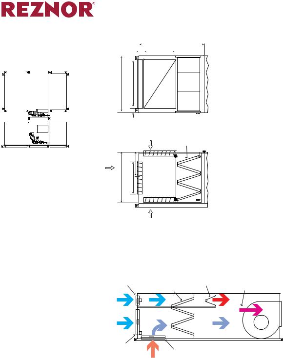
DIMENSIONS
Page Number _______ of ______
|
|
|
|
|
|
|
|
|
|
BURNER |
A |
BLOWER |
|
|
|
|
|
|
|
|
|
|
|
|
|
SECTION |
SECTION |
|
|
|
|
|
|
|
|
|
|
|
|
|
|
|
|
F2 |
|
|
|
DFCH Basic Horizontal Units |
|
|
|
|
|
R |
|
G1 |
D |
|
|
||||
|
|
|
|
|
|
|
|
|
|
|
|||||
Burner Section and Blower Section only |
BURNER & BLOWER |
|
|
|
|
|
|
P |
|
|
|||||
±1/8” (3mm) |
|
|
|
SECTION |
|
|
|
|
|
|
|
|
|
||
|
|
|
A |
|
|
|
|
|
|
|
K1 |
|
|||
|
|
|
R |
|
|
G1 |
|
|
|
|
|
|
|
||
The illiustration to the |
|
|
|
D |
|
|
|
MOTOR |
|
|
|
|
|
||
|
|
|
|
|
|
|
|
|
|
|
|
||||
|
|
|
|
|
|
|
Q1 |
|
|
|
|
|
|||
right |
shows |
Model |
|
|
|
|
|
|
|
|
BLOWERS |
|
|
|
|
DFCH |
with a |
single |
|
|
|
|
|
|
|
|
|
|
|
|
B |
blower. The |
illustra- |
Q1 |
|
|
|
|
|
|
|
|
|
|
|
|
|
tion to the far right |
|
|
|
K1 |
|
|
|
|
|
|
|
|
|||
shows |
Model |
DFCH |
|
|
MOTOR |
|
|
|
B |
|
|
|
K1 |
|
|
|
|
|
|
|
|
|
|
|
|
|
|
|
|
||
with dual blowers. |
|
|
|
BLOWER |
|
|
|
|
|
|
|
|
|
||
Dimensions below are |
|
|
|
P |
|
|
|
|
|
|
|
|
|||
|
|
|
|
|
|
|
|
|
|
|
|
||||
shown in inches and |
|
|
|
|
|
|
|
|
|
|
P |
|
|
||
(millimeters). |
|
|
|
|
|
|
|
N |
|
|
|
|
|
N |
|
|
|
|
|
|
|
|
|
|
|
|
|
|
|
||
|
|
|
|
|
|
|
|
|
|
|
|
|
|
|
|
|
|
|
|
H3 |
|
TOP VIEW |
|
|
|
|
|
TOP VIEW |
|
|
|
|
|
|
|
|
|
|
|
|
|
|
|
|
|
|
|
|
|
|
E |
FRESH AIR |
|
SUPPLY AIR |
|
|
|
H3 |
|
SUPPLY AIR |
|
|
|
|
|
|
DAMPERS |
|
OPTION |
|
|
|
E |
|
|
|
|
||
|
|
|
|
|
|
|
|
OPTION |
|
|
|
||||
|
|
|
|
|
|
|
|
|
|
|
|
|
|||
|
|
|
|
|
|
|
|
|
|
|
|
|
|
|
|
|
|
|
|
|
|
|
L |
|
|
|
|
|
L |
|
|
|
|
|
|
|
|
|
|
|
|
|
|
|
|
|
|
|
|
|
|
CONTROL |
|
|
|
|
CONTROL |
|
|
|
|
||
|
|
|
|
|
|
|
|
PANEL |
|
|
|
|
|
||
|
|
|
|
|
PANEL |
|
|
|
|
|
|
|
|
|
|
|
|
|
M1 |
|
|
G1 |
C |
SUPPLY AIR |
M1 |
|
|
G |
1 |
C |
|
|
|
|
|
|
|
|
|
|
OPTION |
|
|
|
SUPPLY AIR |
||
|
|
|
|
|
|
|
|
|
|
|
|
|
|
||
|
|
|
|
|
|
|
|
|
|
|
|
|
|
|
OPTION |
|
|
|
|
SIDE VIEW |
SUPPLY AIR |
|
J |
SIDE VIEW |
|
SUPPLY AIR |
J |
|
|
||
|
|
|
|
OPTION |
|
|
OPTION |
|
|
|
|||||
|
|
|
|
|
|
|
|
|
|
|
|
||||
SIZE |
A |
B |
C |
D |
E |
F |
G |
H |
J |
K |
L |
M |
N |
P |
Q |
R |
127 |
104 5/8 |
66 |
60 |
5 |
2 |
N/A |
34 1/2 |
58 |
4 |
34 1/2 |
10 3/8 |
56 |
20 |
15 3/4 |
62 |
2 |
130 |
104 5/8 |
66 |
60 |
5 |
2 |
N/A |
37 |
58 |
4 |
37 |
6 3/8 |
56 |
20 |
14 1/2 |
62 |
2 |
133 |
116 5/8 |
74 |
66 |
5 |
2 |
N/A |
43 3/16 |
58 |
4 |
40 |
8 1/8 |
62 |
20 |
17 |
70 |
2 |
1362 |
116 5/8 |
88 |
66 |
5 |
2 |
N/A |
43 3/16 |
58 |
4 |
43 |
8 1/8 |
62 |
20 |
22 1/2 |
84 |
2 |
2182 4 |
84 5/8 |
87 |
40 |
5 |
2 |
N/A |
19 1/8 |
58 |
4 |
22 1/8 |
8 |
36 |
20 |
12 1/2 |
83 |
2 |
2222 4 |
86 5/8 |
104 |
54 |
5 |
2 |
38 5/8 |
27 1/2 |
58 |
4 |
27 1/2 |
11 7/8 |
50 |
20 |
13 3/4 |
100 |
2 |
2272 4 |
116 5/8 |
134 |
60 |
5 |
2 |
58 5/8 |
34 1/2 |
58 |
6 |
34 1/2 |
7 7/8 |
56 |
20 |
19 |
130 |
2 |
2302 4 |
116 5/8 |
134 |
60 |
5 |
2 |
58 5/8 |
37 |
58 |
6 |
37 |
3 7/8 |
56 |
20 |
15 |
130 |
2 |
2332 4 |
124 5/8 |
156 |
66 |
5 |
2 |
66 5/8 |
43 3/16 |
58 |
6 |
40 |
5 5/8 |
62 |
20 |
21 5/8 |
152 |
2 |
2362 4 |
124 5/8 |
156 |
66 |
5 |
2 |
66 5/8 |
43 3/16 |
58 |
6 |
43 |
5 5/8 |
62 |
20 |
17 |
152 |
2 |
SIZE |
A |
B |
C |
D |
E |
F |
G |
H |
J |
K |
L |
M |
N |
P |
Q |
R |
127 |
(2,657) |
(1,676) |
(1,524) |
(127) |
(51) |
N/A |
(876) |
(1,473) |
(102) |
(876) |
(264) |
(1,422) |
(508) |
(400) |
(1,575) |
(51) |
130 |
(2,657) |
(1,676) |
(1,524) |
(127) |
(51) |
N/A |
(940) |
(1,473) |
(102) |
(940) |
(162) |
(1,422) |
(508) |
(368) |
(1,575) |
(51) |
133 |
(2,962) |
(1,880) |
(1,676) |
(127) |
(51) |
N/A |
(1,097) |
(1,473) |
(102) |
(1,016) |
(206) |
(1,575) |
(508) |
(432) |
(1,778) |
(51) |
1362 |
(2,962) |
(2,235) |
(1,676) |
(127) |
(51) |
N/A |
(1,097) |
(1,473) |
(102) |
(1,092) |
(206) |
(1,575) |
(508) |
(572) |
(2,134) |
(51) |
2182 4 |
(2,149) |
(2,210) |
(1,016) |
(127) |
(51) |
N/A |
(486) |
(1,473) |
(102) |
(562) |
(203) |
(914) |
(508) |
(318) |
(2,108) |
(51) |
2222 4 |
(2,200) |
(2,642) |
(1,372) |
(127) |
(51) |
(981) |
(699) |
(1,473) |
(102) |
(699) |
(302) |
(1,270) |
(508) |
(349) |
(2,540) |
(51) |
2272 4 |
(2,962) |
(3,404) |
(1,524) |
(127) |
(51) |
(1,489) |
(876) |
(1,473) |
(152) |
(876) |
(200) |
(1,422) |
(508) |
(483) |
(3,302) |
(51) |
2302 4 |
(2,962) |
(3,404) |
(1,524) |
(127) |
(51) |
(1,489) |
(940) |
(1,473) |
(152) |
(940) |
(98) |
(1,422) |
(508) |
(381) |
(3,302) |
(51) |
2332 4 |
(3,165) |
(3,962) |
(1,676) |
(127) |
(51) |
(1,692) |
(1,097) |
(1,473) |
(152) |
(1,016) |
(143) |
(1,575) |
(508) |
(549) |
(3,861) |
(51) |
2362 4 |
(3,165) |
(3,962) |
(1,676) |
(127) |
(51) |
(1,692) |
(1,097) |
(1,473) |
(152) |
(1,092) |
(143) |
(1,575) |
(508) |
(432) |
(3,861) |
(51) |
11-1/2” inlet and discharge flanges
2DFCH222 and larger burner and blower sections WILL be split for shipping. DFCH136 MAY be split for shipping.
3Service panel access must not be restricted. A minimum clearance of 36” (915mm) is recommended.
4On outdoor dual blower units (size 218 and larger) the roof slopes away from the weatherhousing which covers the control section.
Form RZ-S-DFC Page 8

DFCH ACCESSORIES V-Bank Filter Section
±1/8” (3mm)
Displayed on the following pages are accessory modules for Model DFCH.
The illustration on the left will show the relative location and size of the module.
For example, this page shows the Filter Section on the up stream side of the burner and blower sections.
Dimensional drawings and a dimension table in inches (mm) are also shown.
FILTER |
BURNER |
BLOWER |
SECTION |
SECTION |
SECTION |
CONTROL |
BOX |
Page Number _______ of ______
DIMENSIONS (cont’d)
V-BANK FILTER
SECTION
H A
B D
|
|
TOP VIEW |
|
F |
FILTERS |
|
|
|
C |
E |
|
|
|
SIDE VIEW
SIZE |
A |
B |
C |
D |
E |
F |
127 |
34 |
66 |
60 |
62 |
56 |
2 |
130 |
50 |
66 |
60 |
62 |
56 |
2 |
133 |
50 |
74 |
66 |
70 |
62 |
2 |
136 |
50 |
88 |
66 |
84 |
62 |
2 |
218 |
34 |
87 |
40 |
83 |
36 |
2 |
222 |
34 |
104 |
54 |
100 |
50 |
2 |
227 |
34 |
134 |
60 |
130 |
56 |
2 |
230 |
50 |
134 |
60 |
130 |
56 |
2 |
233 |
50 |
156 |
66 |
152 |
62 |
2 |
236 |
50 |
156 |
66 |
152 |
62 |
2 |
SIZE |
A |
B |
C |
D |
E |
F |
127 |
(864) |
(1,676) |
(1,524) |
(1,575) |
(1,422) |
(51) |
130 |
(1,270) |
(1,676) |
(1,524) |
(1,575) |
(1,422) |
(51) |
133 |
(1,270) |
(1,880) |
(1,676) |
(1,778) |
(1,575) |
(51) |
136 |
(1,270) |
(2,235) |
(1,676) |
(2,134) |
(1,575) |
(51) |
218 |
(864) |
(2,210) |
(1,016) |
(2,108) |
(914) |
(51) |
222 |
(864) |
(2,642) |
(1,372) |
(2,540) |
(1,270) |
(51) |
227 |
(864) |
(3,404) |
(1,524) |
(3,302) |
(1,422) |
(51) |
230 |
(1,270) |
(3,404) |
(1,524) |
(3,302) |
(1,422) |
(51) |
233 |
(1,270) |
(3,962) |
(1,676) |
(3,861) |
(1,575) |
(51) |
236 |
(1,270) |
(3,962) |
(1,676) |
(3,861) |
(1,575) |
(51) |
Louvered Inlet Hood with Filter Section
±1/8” (3mm)
LOUVER |
|
|
FILTER |
BURNER |
BLOWER |
SECTION |
SECTION |
SECTION |
|
CONTROL |
B |
|
BOX |
C
D
LOUVERED INLET |
SECTION |
WITH FILTERS |
A |
TOP VIEW
FILTERS |
SIDE VIEW
SIZE |
A |
B |
C |
D |
127 |
54 |
86 |
60 |
4 |
130 |
68 |
86 |
60 |
4 |
133 |
68 |
94 |
66 |
4 |
136 |
83 |
108 |
66 |
4 |
218 |
34 |
107 |
40 |
4 |
222 |
34 |
124 |
54 |
4 |
227 |
34 |
154 |
60 |
6 |
230 |
50 |
154 |
60 |
6 |
233 |
50 |
176 |
66 |
6 |
236 |
50 |
176 |
66 |
6 |
SIZE |
A |
B |
C |
D |
127 |
(1,372) |
(2,184) |
(1,524) |
(102) |
130 |
(1,727) |
(2,184) |
(1,524) |
(102) |
133 |
(1,727) |
(2,388) |
(1,676) |
(102) |
136 |
(2,108) |
(2,743) |
(1,676) |
(102) |
218 |
(864) |
(2,718) |
(1,016) |
(102) |
222 |
(864) |
(3,150) |
(1,372) |
(102) |
227 |
(864) |
(3,912) |
(1,524) |
(152) |
230 |
(1,270) |
(3,912) |
(1,524) |
(152) |
233 |
(1,270) |
(4,470) |
(1,676) |
(152) |
236 |
(1,270) |
(4,470) |
(1,676) |
(152) |
Form RZ-S-DFC Page 9
DIMENSIONS (cont’d)
Page Number _______ of ______
DFCH ACCESSORIES (cont’d)
Return Air Plenum Section
±1/8” (3mm) |
|
5-3/8” |
|
|
|
|
E |
||||||
|
|
|
|
|
W |
||||||||
|
(137mm) |
|
|
|
|
|
|
|
|||||
|
|
|
|
|
|
|
|
|
|
||||
|
|
|
|
|
|
|
|
|
|
|
|
|
|
|
|
|
|
|
|
|
|
|
|
|
|
|
|
|
|
X |
RETURN AIR |
|
B |
FILTER |
BURNER |
BLOWER |
SECTION |
SECTION |
SECTION |
|
|
4-1/2” |
|
CONTROL |
(114mm) |
|
BOX |
|
C
L
R/A OR F/A
OPTIONS C W
TOP VIEW |
|
R/A OR F/A |
FILTERS |
OPTIONS |
|
R/A OR F/A
OPTIONS
SIDE VIEW
SIZE |
B |
C |
E |
W |
X |
127 |
66 |
60 |
69 |
34 |
57 1/2 |
130 |
66 |
60 |
100 |
48 |
57 1/2 |
133 |
74 |
66 |
103 |
48 |
65 1/2 |
136 |
88 |
66 |
100 |
48 |
79 1/2 |
218 |
87 |
40 |
65 |
36 |
83 |
222 |
104 |
54 |
65 |
50 |
100 |
227 |
134 |
60 |
71 |
56 |
130 |
230 |
134 |
60 |
100 |
56 |
130 |
233 |
156 |
66 |
100 |
62 |
152 |
236 |
156 |
66 |
100 |
62 |
152 |
SIZE |
A |
B |
C |
D |
E |
127 |
(1,676) |
(1,524) |
(1,753) |
(864) |
(1,461) |
130 |
(1,676) |
(1,524) |
(2,540) |
(1,219) |
(1,461) |
133 |
(1,880) |
(1,676) |
(2,616) |
(1,219) |
(1,664) |
136 |
(2,235) |
(1,676) |
(2,540) |
(1,219) |
(2,019) |
218 |
(2,210) |
(1,016) |
(1,651) |
(914) |
(2,108) |
222 |
(2,642) |
(1,372) |
(1,651) |
(1,270) |
(2,540) |
227 |
(3,404) |
(1,524) |
(1,803) |
(1,422) |
(3,302) |
230 |
(3,404) |
(1,524) |
(2,540) |
(1,422) |
(3,302) |
233 |
(3,962) |
(1,676) |
(2,540) |
(1,575) |
(3,861) |
236 |
(3,962) |
(1,676) |
(2,540) |
(1,575) |
(3,861) |
RETURN AIR PLENUM CONFIGURATION
|
|
|
HEATED O/A |
20% INLET |
|
|
MIXED WITH |
DAMPER |
|
|
O/A-R/A |
W/ACTUATOR |
V-BANK |
BURNER |
DOWNSTREAM |
|
FILTERS |
|
FROM BURNER |
OUTDOOR |
O/A-R/A |
|
|
AIR |
|
||
MIXED |
|
||
|
|
||
80% INLET |
|
|
|
DAMPER |
RETURN |
RETURN AIR |
|
W/ACTUATOR |
DAMPER |
||
AIR |
|||
|
W/ACTUATOR |
||
|
|
The Return Air Plenum cabinet is capable of recirculating up to 80% return air.
This allows Model DFC to be used as a combination makeup air and heating unit. A minimum of 20% fresh air must be provided at all times and the balance
(80%) can be a combination of fresh and return air. With the dampers fixed for
80% recirculation, Model DFC functions as a space heater.
The above illustration is a representative diagram for how the ReturnAir Plenum works in a Model DFCH (horizontal unit). A diagram for Model DFCV (vertical unit) with the Return Air Plenum option is not shown, but the function and damper arrangements are similar.
Note: Not available in Canada.
Form RZ-S-DFC Page 10
DIMENSIONS (cont’d)
Page Number _______ of ______
DFCH ACCESSORIES (cont’d) Evaporative Cooling Section
±1/8” (3mm)
|
EVAP. |
|
|
LOUVER |
COOLING |
BURNER |
BLOWER |
SECTION |
SECTION |
SECTION |
SECTION |
CONTROL |
BOX |
LOUVERED |
EVAPORATIVE |
INLET HOOD |
COOLING SECTION |
B |
A |
C |
|
|
G |
|
TOP VIEW |
FILTERS |
D |
FRESH |
AIR |
FLOW |
SIDE VIEW
|
|
|
SIZE |
A |
B |
C |
D |
E |
F |
G |
2” FILTERS |
|
|
|
127 |
90 |
24 |
134 |
93 |
66 |
60 |
20 |
(15) 16x25 |
|
|
|
(10) 20x25 |
||||||||
|
|
|
130 |
80 |
24 |
134 |
96 |
66 |
60 |
20 |
(15) 16x25 |
|
|
|
(10) 20x25 |
||||||||
|
|
|
133 |
80 |
24 |
134 |
112 |
74 |
66 |
20 |
(20) 16x25 |
|
|
|
(10) 20x25 |
||||||||
|
|
|
136 |
100 |
24 |
170 |
125 |
88 |
66 |
20 |
(36) 20x25 |
|
|
|
|
|
|
|
|
|
|
|
(6) 20x16 |
|
|
|
218 |
70 |
24 |
110 |
77 |
87 |
40 |
20 |
(8) 15x25 |
|
|
|
(8) 20x25 |
||||||||
|
|
|
|
|
|
|
|
|
|
|
|
|
|
|
222 |
70 |
24 |
132 |
85 |
104 |
54 |
20 |
(20) 20x25 |
|
|
|
227 |
90 |
38 |
170 |
110 |
134 |
60 |
20 |
(20) 20x25 |
|
|
|
(15) 20x16 |
||||||||
|
|
|
230 |
102 |
38 |
230 |
120 |
134 |
60 |
20 |
(36) 20x25 |
|
|
|
(18) 16x25 |
||||||||
|
|
|
233 |
102 |
38 |
230 |
120 |
156 |
66 |
20 |
(36) 20x25 |
|
|
|
(18) 16x25 |
||||||||
|
|
|
236 |
102 |
38 |
254 |
120 |
156 |
66 |
20 |
(40) 20x25 |
|
|
|
(20) 16x25 |
||||||||
|
|
|
SIZE |
A |
B |
C |
D |
E |
F |
F |
2” FILTERS |
|
|
|
127 |
(2,286) |
(610) |
(3,404) |
(2,362) |
(1,676) |
(1,524) |
(508) |
(15) 16x25 |
|
|
|
(10) 20x25 |
||||||||
|
|
|
130 |
(2,032) |
(610) |
(3,404) |
(2,438) |
(1,676) |
(1,524) |
(508) |
(15) 16x25 |
|
|
|
(10) 20x25 |
||||||||
|
|
|
133 |
(2,032) |
(610) |
(3,404) |
(2,845) |
(1,880) |
(1,676) |
(508) |
(20) 16x25 |
|
|
|
(10) 20x25 |
||||||||
|
|
|
136 |
(2,540) |
(610) |
(4,318) |
(3,175) |
(2,235) |
(1,676) |
(508) |
(36) 20x25 |
|
|
|
|||||||||
|
|
|
(6) 20x16 |
||||||||
|
|
|
218 |
(1,778) |
(610) |
(2,794) |
(1,956) |
(2,210) |
(1,016) |
(508) |
(8) 15x25 |
|
|
|
(8) 20x25 |
||||||||
|
|
|
222 |
(1,778) |
(610) |
(3,353) |
(2,159) |
(2,642) |
(1,372) |
(508) |
(20) 20x25 |
|
|
|
227 |
(2,286) |
(965) |
(4,318) |
(2,794) |
(3,404) |
(1,524) |
(508) |
(20) 20x25 |
|
E |
(15) 20x16 |
|||||||||
|
|
|
230 |
(2,591) |
(965) |
(5,842) |
(3,048) |
(3,404) |
(1,524) |
(508) |
(36) 20x25 |
|
|
|
(18) 16x25 |
||||||||
|
|
|
233 |
(2,591) |
(965) |
(5,842) |
(3,048) |
(3,962) |
(1,676) |
(508) |
(36) 20x25 |
|
|
|
(18) 16x25 |
||||||||
|
|
|
236 |
(2,591) |
(965) |
(6,452) |
(3,048) |
(3,962) |
(1,676) |
(508) |
(40) 20x25 |
|
|
|
(20) 16x25 |
||||||||
|
|
|
|
|
|
|
|
|
|
|
|
|
|
|
|
|
|
|
|
|
|
|
|
F
Form RZ-S-DFC Page 11
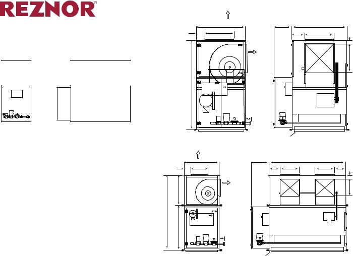
DFCH ACCESSORIES (cont’d) Cooling Coil Section
±1/8” (3mm)
COIL CABINET |
COIL CABINET |
WITH DOWN |
WITH HORIZ. |
DISCHARGE |
DISCHARGE |
SECTION |
SECTION |
A |
|
|
|
|
B |
|
|
F |
J |
|
|
G |
|
|
|
|
|
|
||
|
|
|
|
|
|
|
|
|
|
D |
|
|
D |
K |
|
E |
|
K |
E |
|
|
|
|
|
|
||
|
|
TOP VIEW |
|
|
|
|
L |
|
C |
L |
|
H |
C |
SIDE VIEW
Page Number _______ of ______
DIMENSIONS (cont’d)
|
|
COOLING |
CONTROL |
|
|
BOX |
|
BURNER |
BLOWER |
COIL |
|
SECTION |
SECTIONSECTION |
|
|
|
|
|
|
|
|
|
|
|
|
|
|
|
|
|
|
|
|
|
|
|
|
|
|
|
|
|
|
SIZE |
A |
|
B |
C |
D |
E |
G |
H |
|
J |
K |
L |
|
127 |
95 |
|
61 |
94 |
105 |
95 |
5 |
84 |
4 |
1/2 |
90 |
85 |
|
|
|
|
|
|
|
|
|
|
|
|
|
|
|
130 |
102 |
|
66 |
105 |
115 |
105 |
5 |
95 |
4 |
1/2 |
100 |
96 |
|
133 |
102 |
|
66 |
109 |
125 |
115 |
5 |
99 |
4 |
1/2 |
110 |
100 |
|
|
|
|
|
|
|
|
|
|
|
|
|
||
136 |
115 |
|
71 |
119 |
141 |
131 |
5 |
109 |
4 1/2 |
126 |
110 |
||
218 |
74 |
|
50 |
65 |
113 |
103 |
5 |
55 |
4 |
1/2 |
98 |
56 |
|
|
|
|
|
|
|
|
|
|
|
|
|
|
|
222 |
84 |
|
60 |
78 |
130 |
120 |
5 |
68 |
4 |
1/2 |
115 |
69 |
|
227 |
106 |
|
70 |
103 |
179 |
169 |
5 |
93 |
|
6 |
164 |
94 |
|
|
|
|
|
|
|
|
|
|
|
|
|
|
|
230 |
122 |
|
80 |
119 |
193 |
183 |
5 |
109 |
|
6 |
178 |
110 |
|
233 |
123 |
|
80 |
122 |
214 |
204 |
5 |
112 |
|
6 |
199 |
113 |
|
236 |
136 |
|
90 |
131 |
222 |
212 |
5 |
121 |
|
6 |
207 |
122 |
|
SIZE |
A |
|
B |
C |
D |
E |
G |
H |
|
J |
K |
L |
|
127 |
(2,413) |
|
(1,549) |
(2,388) |
(2,667) |
(2,413) |
(127) |
(2,134) |
(114) |
(2,286) |
(2,159) |
||
130 |
(2,591) |
|
(1,676) |
(2,667) |
(2,921) |
(2,667) |
(127) |
(2,413) |
(114) |
(2,540) |
(2,438) |
||
133 |
(2,591) |
|
(1,676) |
(2,769) |
(3,175) |
(2,921) |
(127) |
(2,515) |
(114) |
(2,794) |
(2,540) |
||
|
|
|
|
|
|
|
|
|
|
|
|
||
136 |
(2,921) |
|
(1,803) |
(3,023) |
(3,581) |
(3,327) |
(127) |
(2,769) |
(114) |
(3,200) |
(2,794) |
||
218 |
(1,880) |
|
(1,270) |
(1,651) |
(2,870) |
(2,616) |
(127) |
(1,397) |
(114) |
(2,489) |
(1,422) |
||
|
|
|
|
|
|
|
|
|
|
|
|
||
222 |
(2,134) |
|
(1,524) |
(1,981) |
(3,302) |
(3,048) |
(127) |
(1,727) |
(114) |
(2,921) |
(1,753) |
||
227 |
(2,692) |
|
(1,778) |
(2,616) |
(4,547) |
(4,293) |
(127) |
(2,362) |
(152) |
(4,166) |
(2,388) |
||
|
|
|
|
|
|
|
|
|
|
|
|
||
230 |
(3,099) |
|
(2,032) |
(3,023) |
(4,902) |
(4,648) |
(127) |
(2,769) |
(152) |
(4,521) |
(2,794) |
||
233 |
(3,124) |
|
(2,032) |
(3,099) |
(5,436) |
(5,182) |
(127) |
(2,845) |
(152) |
(5,055) |
(2,870) |
||
|
|
|
|
|
|
|
|
|
|
|
|
||
236 |
(3,454) |
|
(2,286) |
(3,327) |
(5,639) |
(5,385) |
(127) |
(3,073) |
(152) |
(5,258) |
(3,099) |
||
Form RZ-S-DFC Page 12
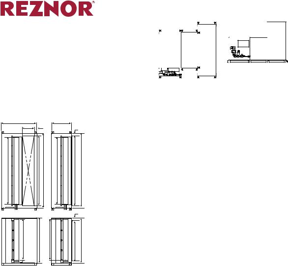
DIMENSIONS (cont’d)
Page Number _______ of ______
|
|
SUPPLY AIR |
|
|
DFCV Basic Vertical Units |
|
OPTION |
|
|
|
C |
H |
B |
|
Burner Section and Blower Section only |
F |
L |
G |
K |
|
||||
±1/8” (3mm) |
|
|
|
M |
|
|
|
|
BLOWER |
SUPPLY AIR |
L |
|
SECTION |
OPTION |
||
|
BLOWER |
|
|
SECTION |
|
BLOWER |
|
|
|
|
A |
CONTROL |
CONTROL |
|
PANEL |
BURNER |
|
|
BOX |
MOTOR |
|
BURNER |
SECTION |
|
SECTION |
|
|
|
|
|
|
|
N |
NOTE: Dimensions are the same for upflow and downflow units. On a floor-mounted, downflow unit with side discharge is ordered (Option AQ30), a four inch base is included.
SIDE VIEW |
FRESH AIR |
FRONT VIEW |
|
DAMPERS |
|
|
SUPPLY AIR |
|
|
|
|
|
|
OPTION |
C |
H |
|
B |
|
|
F |
L |
G |
K |
K |
G |
|
|
|
|
|
M |
|
|
|
|
|
|
|
|
BLOWER |
|
|
|
|
BLOWERS |
L |
SECTION |
D |
SUPPLY AIR |
|
|
||
|
OPTION |
|
|
|
|
|
|
|
|
|
|
|
|
A |
|
|
|
|
|
|
|
|
CONTROL |
|
|
MOTOR |
|
|
|
|
|
|
|
|
BURNER |
|
PANEL |
|
|
|
|
SECTION |
E |
|
|
|
|
|
|
|
N |
|
|
|
|
|
|
|
|
SIDE VIEW |
|
|
FRESH AIR |
|
FRONT VIEW |
|
|
|||
|
|
|
|
|
|
|
|
DAMPERS |
|
|
|
|
|
|
|
|
|
|
|
|
|
|
|
|
|
|
|
|
|
SIZE |
A |
B |
C |
D |
E |
|
F |
|
G |
H |
K |
L |
M |
N |
127 |
104 5/8 |
66 |
60 |
N/A |
N/A |
10 3/8 |
|
15 3/4 |
20 |
34 1/2 |
34 1/2 |
3 7/8 |
3 |
|
130 |
104 5/8 |
66 |
60 |
N/A |
N/A |
6 |
3/8 |
|
14 1/2 |
20 |
37 |
37 |
3 7/8 |
3 |
133 |
116 5/8 |
74 |
66 |
N/A |
N/A |
8 |
1/8 |
|
17 |
20 |
40 |
43 3/16 |
3 7/8 |
3 |
136 |
116 5/8 |
88 |
66 |
N/A |
N/A |
8 |
1/8 |
|
22 1/2 |
20 |
43 |
43 3/16 |
3 7/8 |
3 |
218 |
84 5/8 |
87 |
40 |
N/A |
N/A |
|
8 |
|
12 1/2 |
20 |
22 1/8 |
19 1/8 |
4 |
3 |
222 |
86 5/8 |
104 |
54 |
38 5/8 |
58 |
11 7/8 |
|
13 3/4 |
20 |
27 1/2 |
27 1/2 |
4 |
3 |
|
227 |
116 5/8 |
134 |
60 |
58 5/8 |
58 |
7 |
7/8 |
|
19 |
20 |
34 1/2 |
34 1/2 |
4 |
3 |
230 |
116 5/8 |
134 |
60 |
58 5/8 |
58 |
3 |
7/8 |
|
15 |
20 |
37 |
37 |
4 |
3 |
233 |
124 5/8 |
156 |
66 |
66 5/8 |
58 |
5 |
5/8 |
|
21 5/8 |
20 |
40 |
43 3/16 |
4 |
3 |
236 |
124 5/8 |
156 |
66 |
66 5/8 |
58 |
5 |
5/8 |
|
17 |
20 |
43 |
43 3/16 |
4 |
3 |
SIZE |
A |
B |
C |
D |
E |
|
F |
|
G |
H |
K |
L |
M |
N |
127 |
(2,657) |
(1,676) |
(1,524) |
N/A |
N/A |
(264) |
|
(400) |
(508) |
(876) |
(876) |
(98) |
(76) |
|
130 |
(2,657) |
(1,676) |
(1,524) |
N/A |
N/A |
(162) |
|
(368) |
(508) |
(940) |
(940) |
(98) |
(76) |
|
133 |
(2,962) |
(1,880) |
(1,676) |
N/A |
N/A |
(206) |
|
(432) |
(508) |
(1,016) |
(1,097) |
(98) |
(76) |
|
136 |
(2,962) |
(2,235) |
(1,676) |
N/A |
N/A |
(206) |
|
(572) |
(508) |
(1,092) |
(1,097) |
(98) |
(76) |
|
218 |
(2,149) |
(2,210) |
(1,016) |
N/A |
N/A |
(203) |
|
(318) |
(508) |
(562) |
(486) |
(102) |
(76) |
|
222 |
(2,200) |
(2,642) |
(1,372) |
(981) |
(1,473) |
(302) |
|
(349) |
(508) |
(699) |
(699) |
(102) |
(76) |
|
227 |
(2,962) |
(3,404) |
(1,524) |
(1,489) |
(1,473) |
(200) |
|
(483) |
(508) |
(876) |
(876) |
(102) |
(76) |
|
230 |
(2,962) |
(3,404) |
(1,524) |
(1,489) |
(1,473) |
(98) |
|
(381) |
(508) |
(940) |
(940) |
(102) |
(76) |
|
233 |
(3,165) |
(3,962) |
(1,676) |
(1,692) |
(1,473) |
(143) |
|
(549) |
(508) |
(1,016) |
(1,097) |
(102) |
(76) |
|
236 |
(3,165) |
(3,962) |
(1,676) |
(1,692) |
(1,473) |
(143) |
|
(432) |
(508) |
(1,092) |
(1,097) |
(102) |
(76) |
|
11-1/2” inlet and discharge flanges
2DFCV233 and larger burner and blower sections WILL be split for shipping.
3Service panel access must not be restricted. A minimum clearance of 36” (915mm) is recommended.
Form RZ-S-DFC Page 13

DIMENSIONS (cont’d)
Page Number _______ of ______
DFCV ACCESSORIES (cont’d) |
|
|||
Return Air Plenum Section |
|
|
||
±1/8” (3mm) |
|
|
|
|
|
|
|
BLOWER |
|
|
|
|
SECTION |
|
CONTROL |
|
|
|
|
|
BOX |
|
|
|
|
|
|
BURNER |
|
|
|
|
SECTION |
|
|
|
|
RETURN AIR |
|
|
|
|
PLENUM |
|
|
|
|
FILTER SECTION |
|
|
|
C |
|
|
|
|
|
FILTERS |
|
R/A OR E |
|
R/A OR |
|
|
FRESH |
W |
|
FRESH |
|
AIR |
|
AIR |
|
|
FLOW |
|
|
FLOW |
|
|
J |
|
4-1/4” |
|
|
|
C |
X |
|
|
5-3/8” |
(108mm) |
||
|
L |
B |
||
(137mm) |
W |
|
||
|
|
|||
SIDE VIEW |
|
FRONT VIEW |
||
|
|
|
||
RETURN AIR PLENUM CONFIGURATION
HEATED O/A |
|
|
MIXED WITH |
|
|
O/A-R/A |
|
|
DOWNSTREAM |
|
|
FROM BURNER |
|
|
BURNER |
|
|
V-BANK |
RETURN AIR |
|
FILTERS |
||
DAMPER |
||
|
||
|
W/ACTUATOR |
|
O/A-R/A |
|
|
MIXED |
RETURN |
|
|
||
|
AIR |
|
20% INLET |
|
|
DAMPER |
80% INLET |
|
W/ACTUATOR |
||
DAMPER |
||
OUTDOOR |
||
AIR |
W/ACTUATOR |
SIZE |
B |
C |
E |
W |
X |
127 |
66 |
60 |
69 |
34 |
57 1/2 |
|
|
|
|
|
|
130 |
66 |
60 |
100 |
48 |
57 1/2 |
133 |
74 |
66 |
103 |
48 |
65 1/2 |
|
|
|
|
|
|
136 |
88 |
66 |
100 |
48 |
79 1/2 |
218 |
87 |
40 |
65 |
36 |
8 3 |
222 |
104 |
54 |
65 |
50 |
100 |
227 |
134 |
60 |
71 |
56 |
130 |
230 |
134 |
60 |
100 |
56 |
130 |
|
|
|
|
|
|
233 |
156 |
66 |
100 |
62 |
15 2 |
236 |
156 |
66 |
100 |
62 |
152 |
SIZE |
A |
B |
C |
D |
E |
127 |
(1,676) |
(1,524) |
(1,753) |
(864) |
(1,461) |
|
|
|
|
|
|
130 |
(1,676) |
(1,524) |
(2,540) |
(1,219) |
(1,461) |
133 |
(1,880) |
(1,676) |
(2,616) |
(1,219) |
(1,664) |
|
|
|
|
|
|
136 |
(2,235) |
(1,676) |
(2,540) |
(1,219) |
(2,019) |
218 |
(2,210) |
(1,016) |
(1,651) |
(914) |
(2,108) |
|
|
|
|
|
|
222 |
(2,642) |
(1,372) |
(1,651) |
(1,270) |
(2,540) |
227 |
(3,404) |
(1,524) |
(1,803) |
(1,422) |
(3,302) |
230 |
(3,404) |
(1,524) |
(2,540) |
(1,422) |
(3,302) |
233 |
(3,962) |
(1,676) |
(2,540) |
(1,575) |
(3,861) |
236 |
(3,962) |
(1,676) |
(2,540) |
(1,575) |
(3,861) |
The Return Air Plenum cabinet is capable of recirculating up to 80% return air. This allows Model DFC to be used as a combination makeup air and heating unit. A minimum of 20% fresh air must be provided at all times and the balance (80%) can be a combination of fresh and return air. With the dampers fixed for
80% recirculation, Model DFC functions as a space heater.
See the illustration for the ReturnAir Plenum for Model DFCH (horizontal unit).A diagram for Model DFCV (vertical unit) with the Return Air Plenum option is not shown, but the function and damper arrangements are similar.
Note: Not available in Canada.
Form RZ-S-DFC Page 14
 Loading...