

Page 1

Workshop Repair Manual
Manual gearbox
Type Range
JC7 Scénic RX4
Reduction gearing section
For the gearbox section
refer to the JB - JC manual
77 11 298 942
"The repair methods given by the manufacturer in this document are based on the
technical specifications current when it was prepared.
The methods may be modified as a result of changes introduced by the manufacturer
in the production of the various component units and accessories from which his
vehicles are constructed."
FEBRUARY 2001
© RENAULT 2001
EDITION ANGLAISE
All copyrights reserved by Renault.
Copying or translating, in part or in full, of this document or use of the service part
reference numbering system is forbidden without the prior written authority of Renault.
Page 2

Contents
MANUAL GEARBOX
21
Identification 21-1
Gears 21-1
Section and tightening torques (in daNm) 21-3
Tightening torques (in daNm) 21-4
Special tooling 21-5
Repairing the reduction gearing 21-6
Page
Page 3
MANUAL GEARBOX
MANUAL GEARBOX
121
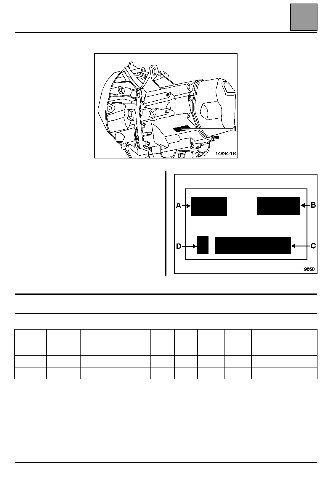
Marking (1), on the gearbox casing, indicates:
A Gearbox type
B Gearbox index
C Fabrication number
D Factory of manufacture
Identification
Identification
21
Ratios
Index Type 1
JC7-000 J64 (F4R) 11/41 21/43 28/39 31/34 37/33 11/39 15/61 22/18 15/41
JC7-001 J64 (F9Q) 11/41 21/43 28/37 35/34 39/31 11/39 15/61 22/18 15/41
st
nd
2
rd
3
th
4
th
5
Re-
verse
gear
Final
drive
Tachome-
ter
21-1
Reduc-
tion
gearing
Page 4
MANUAL GEARBOX
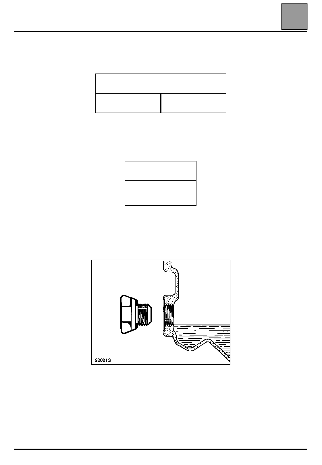
CAPACITY (in litres)
Capacities - Lubricants
Capacities - Lubricants
5-speed gearbox
JC7 3.3
Viscosity grade
21
TRX 75W 80W
CHECKING THE LEVEL
Fill up to the level of the hole
21-2
Page 5
MANUAL GEARBOX
Section and tightening torques (in daNm)
Section and tightening torques (in daNm)
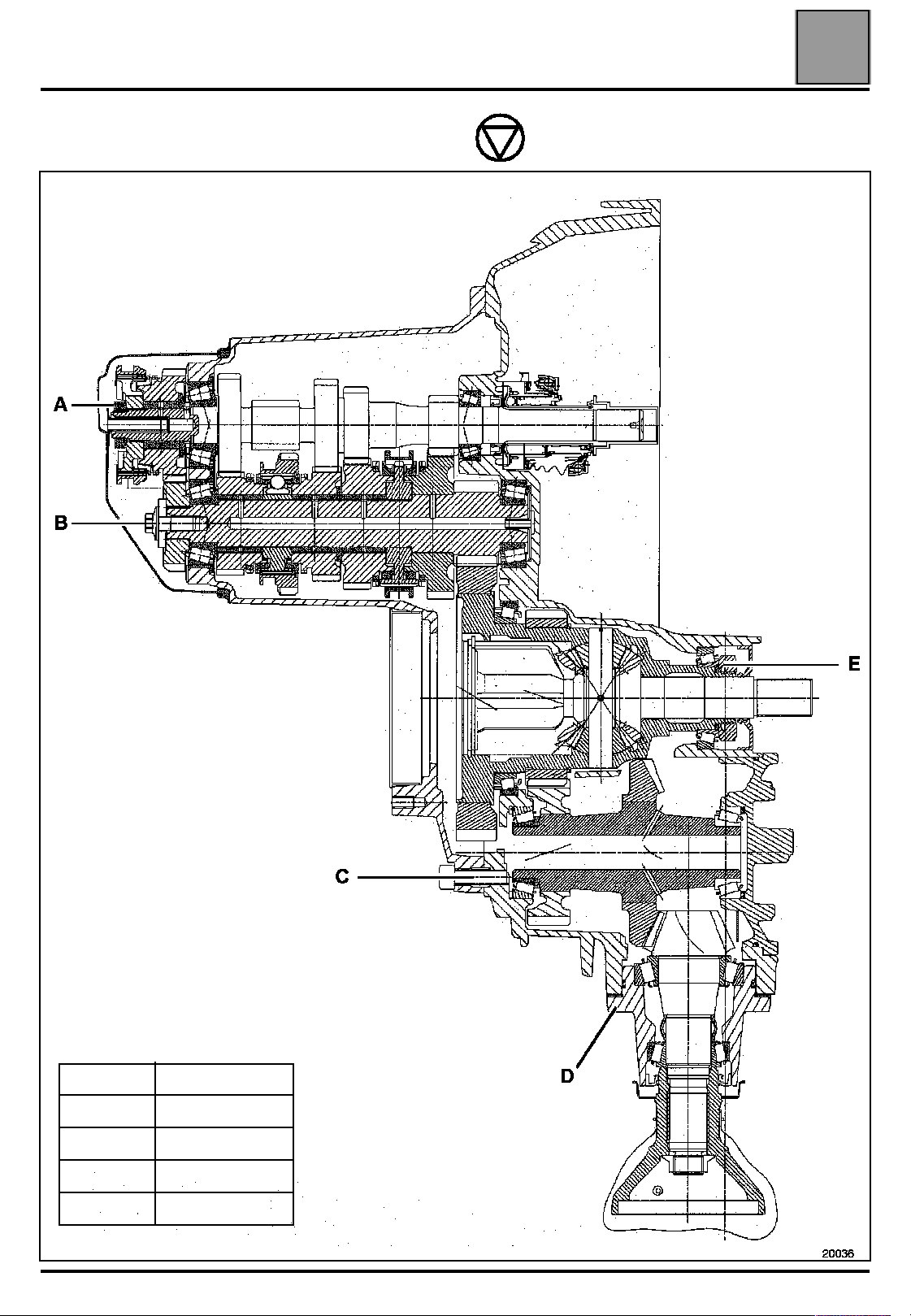
MANUAL GEARBOX JC7 (tightening torques in daNm)
21
A16
B 7
C 3.5
D 3.5
E15
20036
21-3
Page 6
MANUAL GEARBOX
Tightening torques (in danm)
Tightening torques (in danm)
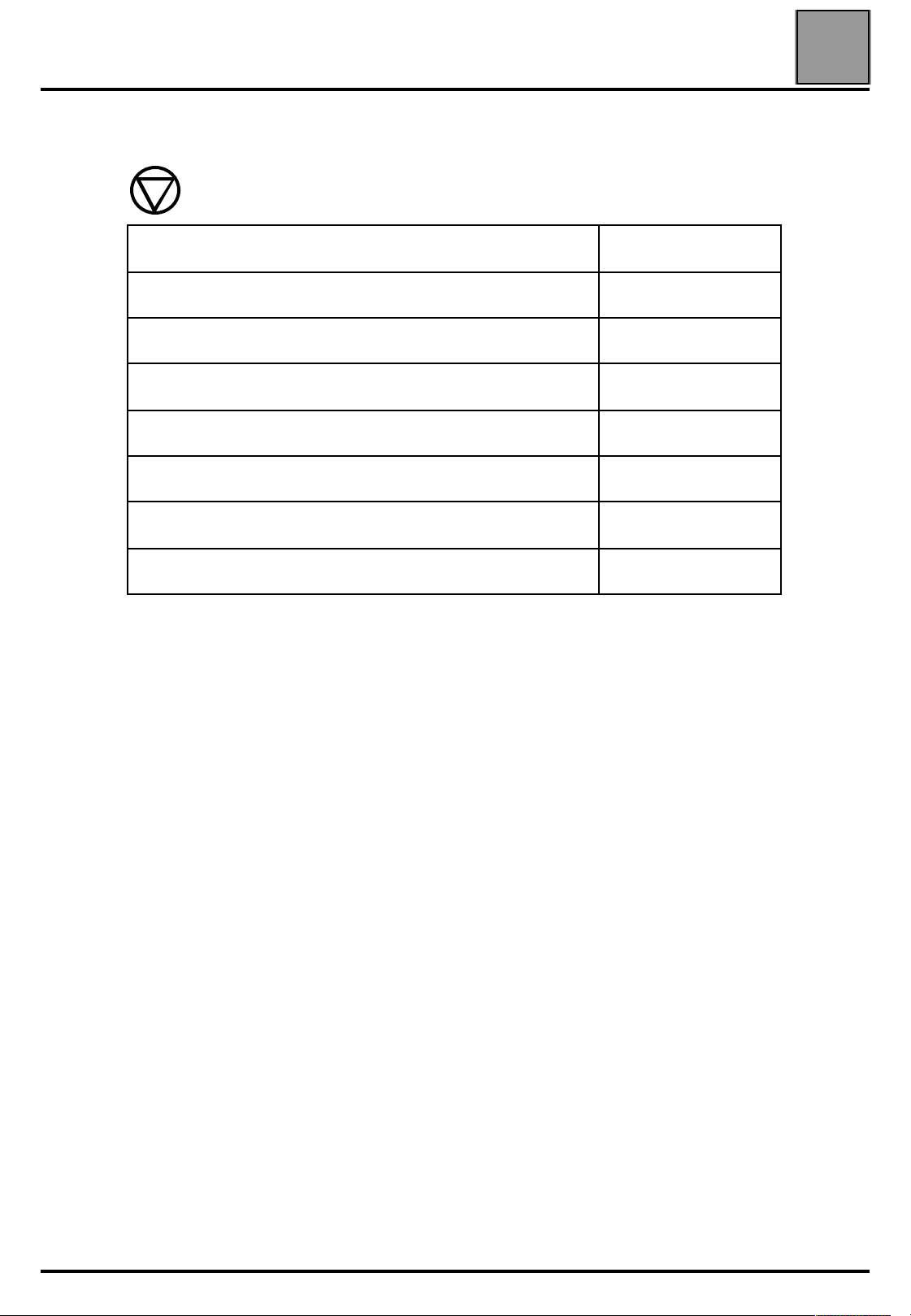
Description Torque in daNm
Bolt joining the gearbox casing to the clutch casing 2.5
th
Body (point of resistance of 5
Rear cover bolt 2.5
Drain plug 2.5
Reversing light switch 2.5
Left driveshaft gaiter mounting bolt 2.5
) 2
21
Joining the gearbox to the cylinder casing 5
21-4
Page 7

MANUAL GEARBOX
Special tooling
Special tooling
B. Vi. 1161 Steel plate to attach DTI gauge + pre-load adjust shims
B. Vi. 1389 Rules for measurements on automatic gearbox
B. Vi. 1419 Bearing positioning tool
B. Vi. 1554 Reduction gearing repair kit
B. Vi. 1556 Tool for supporting the intake flange
B. Vi. 1581 Gearbox support plate
B. Vi. 1582 Input shaft support plate
RECOMMENDED TOOLING
General purpose puller pliers ∅ 42 (example: U 49M + U49D8 Facom)
Swivel head DESVIL stand
Torque testing wrench
21
21-5
Page 8

MANUAL GEARBOX
Repairing the reduction gearing
Repairing the reduction gearing
DISMANTLING THE REDUCTION GEARING
Fit the B. Vi. 1581 support plate on a DESVIL stand.
Fit the gearbox on the B. Vi. 1581 support.
21
REMOVING BEARINGS
Remove the bearings using an antisticking pin.
NOTE: the gearbox differential must be removed
(refer to the JB-JC manual for removing/refitting)
before any operation can be carried out on the
reduction gearing.
Remove:
– the reduction gearing shaft (A),
– the cover (B).
Remove the reduction gearing.
On the inside, it is necessary to break the bearing
cage in order to position the jaws of the antisticking pin
on the bearing flange base.
21-6
Page 9

MANUAL GEARBOX
Repairing the reduction gearing
RE-FITTING THE BEARINGS
Fit the bearings as far as the thrust bearing on the
casing using index tool D from the B. Vi. 1554 kit.
21
Cover side
Fit onto B. Vi. 1582.
REMOVING BEARING RETAINERS
Remove the retainers using a ∅ 42 extractor and an
inertia extractor.
WARNING: take care not to mix the pre-stressed
setting shims.
Gearbox housing side
REFITTING THE RETAINERS
After refitting the original prestressed shim, refit the
housing side retainer to the press using tools C-F from
the B. Vi. 1554 kit and the B. Vi. 1419 rod.
WARNING: the shim and the cover side retainer must
be refitted after their pre-stress value has been
determined.
21-7
Page 10

MANUAL GEARBOX
Repairing the reduction gearing
SETTING THE REDUCTION GEARING
PRE-STRESS
Housing side: dimension X
Position the reduction gearing in the housing and fit
the retainer, cover side, on its bearing.
Fit tool G from the B. Vi. 1554 kit on the bearing
retainer.
Pass the cable inside the reduction gearing and attach
a 20 kg weight
21
Cover side: dimension X'
Measure between the cover plane (A) and the mating
face of the pre-stressing shim (B) using B. Vi. 1389
and calculate the difference to determine dimension
X'.
Remember to subtract the thickness of the rule.
Measuring on the cover plane:
19258
Measure between the housing plane and the top of the
retainer using B. Vi. 1389 (dimension X).
Remember to subtract the thickness of the rule.
19260
Measuring on the shim mating face:
19261
19259
21-8
Page 11

MANUAL GEARBOX
Repairing the reduction gearing
Measure the difference between the two dimensions
(X and X') and add 0.09 mm to this amount to
determine the thickness of the pre-stressing shim.
Example:
X X' Value for pre-stressing shim
14.65 12.97
Select the shim closest to 1.77 from the kit.
Fit the shim and the retainer using tool C-F from the
B. Vi. 1554 kit.
14.65 - 12.97 = 1.68 (+0.09) =
1.77
21
Fit the cover with a new O-ring and tighten the bolts to
a torque of 3.5 daNm.
19262
19263
21-9
Page 12

MANUAL GEARBOX
Repairing the reduction gearing
REPLACING THE INPUT SHAFT BEARINGS
Measure the distance between the end of the shaft
and the conical spacer shim (A), before removing the
shaft on the casing.
Then read the thickness of this shim (A).
21
Remove:
– the clamp and the input shaft using the press,
19264
Fit the assembly on B. Vi. 1582 and remove the prestressing nut using B. Vi. 1556.
– the bearing using an antistick pin.
21-10
Page 13

MANUAL GEARBOX
Repairing the reduction gearing
Refit the bearing using the B tool from the B. Vi. 1554
kit.
21
Refit the retainers using tools A and C-F from the
B. Vi. 1554 kit.
Remove the interior retainers using a roll pin punch.
21-11
Page 14

MANUAL GEARBOX
Repairing the reduction gearing
NOTE: the bearings are pre-stressed by deformation
of the spacer (A).
A new spacer must be fitted and use tool D from the
B. Vi. 1554 kit to fit a small bearing to leave a slight
play (B) so that the spacer is not deformed
prematurely.
21
Fit the lip seal using tool E from the B. Vi. 1554 kit.
18560
Fit the shaft in the casing, with a new pre-stressing
spacer, and fit the small bearing using the press and
tool D from the B. Vi. 1554 kit.
19266
19265
21-12
Page 15

MANUAL GEARBOX
Repairing the reduction gearing
Partly fit the inlet clamp (so that there is always a slight
play between the bearing and the pre-stressing
spacer).
21
Check the bearings' pre-stress using a torque tester
(A).
The inlet shaft must turn under a torque of 1.15 Nm.
If the torque value is incorrect, gradually tighten the
nut to obtain the correct pre-stress setting.
WARNING: never loosen the nut: if pre-stressing
is too high, repeat the removal operation to
replace the pre-stress spacer.
Fit the assembly on B. Vi. 1582.
Tighten the nut to approximately 26 daNm using
B. Vi. 1556.
19267
21-13
Page 16

MANUAL GEARBOX
Repairing the reduction gearing
CHECKING THE CONIC DISTANCE
Measure between the end of the shaft and the conical
spacer shim (as during removal).
21
Fit the assembly on the gearbox with a new O-ring and
tighten the bolts to a torque of 3.5 daNm.
19264
Calculate the difference between these two values
(before removal and after refitting).
Increase the shim if the value is higher.
Decrease the shim if the value is higher.
Example (in mm):
Before
removal
56.80 56.90 + 0.10 2.10
Value of new conic distance shim:
2.10 + 0.10 = 2.20
Select from the kit the shim closest to 2.20.
After
refitting
Difference
Value of
original
shim
21-14
Page 17

MANUAL GEARBOX
Repairing the reduction gearing
Check play of teeth:
Fit a bolt (V) in one of the inlet shaft flange holes.
Fit a dial gauge using the plate from B. Vi. 1161 so
that the probe is in contact with one of the bolt flats.
Measure the play by gently swivelling the inlet shaft.
Measure this play four times, turning the inlet shaft
about ten times, and moving the bolt (V) into another
hole in the flange.
Average it.
The play must be between 0.15 and 0.25 mm.
21
If the play is not correct, reduce or increase the shims
which are behind the reduction gearing bearing
retainers.
To reduce the play, decrease the shim thickness on the
side opposite the ring and transfer this to the ring side
(to retain the same bearing pre-stress).
To increase the play, do the reverse.
21-15
 Loading...