

Page 1

Workshop Repair Manual
Manual gearboxes
Vehicle
Type
JB0 JB1 JB2 JB3 JB4 JB5 JC5
Renault 5 X X X X X
Extra X X X
Renault 9 X X X X X
Renault 11 X X X X X
Renault 19 X X X X X
Renault 21 X X
Clio X X XXXX
Twingo X
Laguna X X
Mégane X X X
This document cancels and replaces JB Gearbox manual part number
77 11 093 922 and JC5 Gearbox manual part number
77 11 092 186
and technical notes
n° 1978, 2127, 2229A, 2284A, 2383A, 2457A.
77 11 192 787 FEBRUARY 1997 Edition Anglaise
"The repair methods given by the manufacturer in this document are
based on the technical specifications current when it was prepared.
The methods may be modified as a result of changes by the manufacturer
in the production of the various component units and accessories from
which his vehicles are constructed".
C
Renault 1997
All copyrights reserved by Renault.
Copying or translating, in part or in full, of this document or use of the
service part reference numbering system is forbidden without the prior
written authority of Renault.
Page 2

Contents
ENSEMBLE MOTEUR ET BAS
MANUAL GEARBOX
21
Pages
Section view
Identification
Cross section - tightening torques
Gears
Capacity - Lubricants
Special points
Modifications
Consumables
Parts which must always be changed
Special tools
Gearbox repair
Shafts
Differential
21-1
21-2
21-3
21-8
21-28
21-29
21-30
21-32
21-32
21-33
21-37
21-44
21-62
Internal controls
Lubrication channel
Reverse gear shaft
Reverse gear brake
Speedometer
Thrust pad guide tube
Assembling the housings
Exploded view parts directory
Exploded views
21-76
21-79
21-80
21-81
21-84
21-89
21-97
21-107
21-108
Page 3
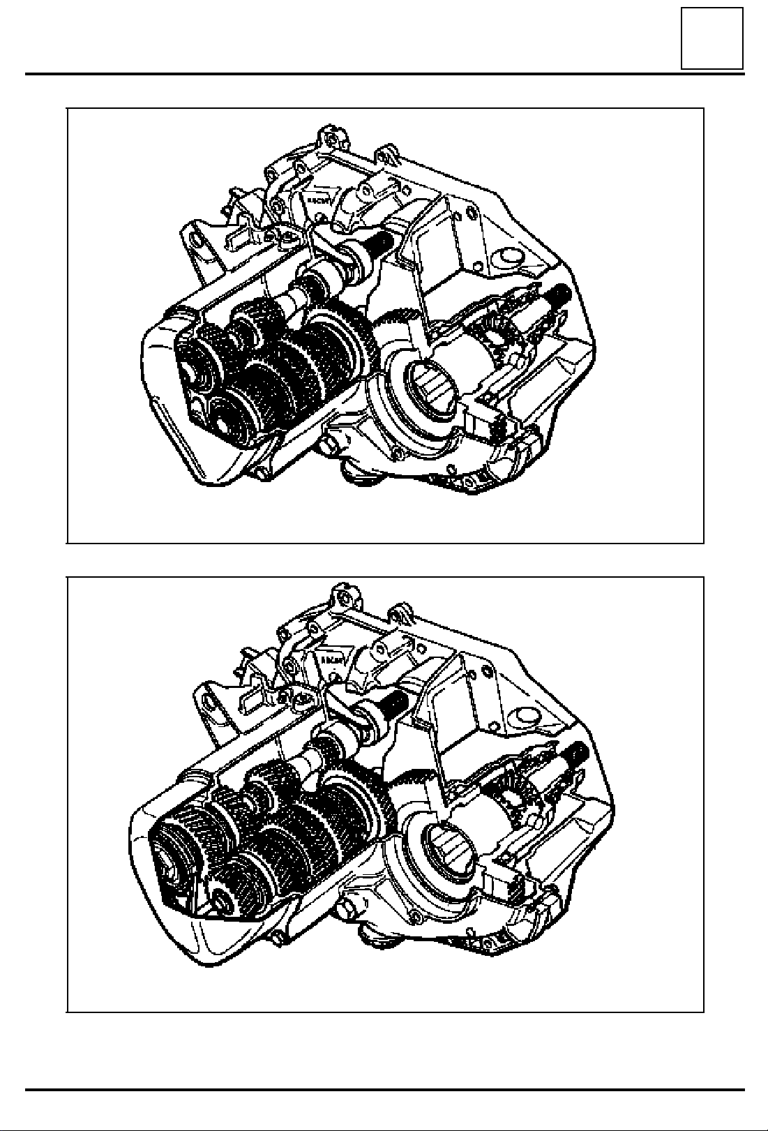
JB0
JB2
JB4
MANUAL GEARBOX
Section view
21
JB1
JB3
JB5
JC5
DI2101
21-1
DI2102
Page 4
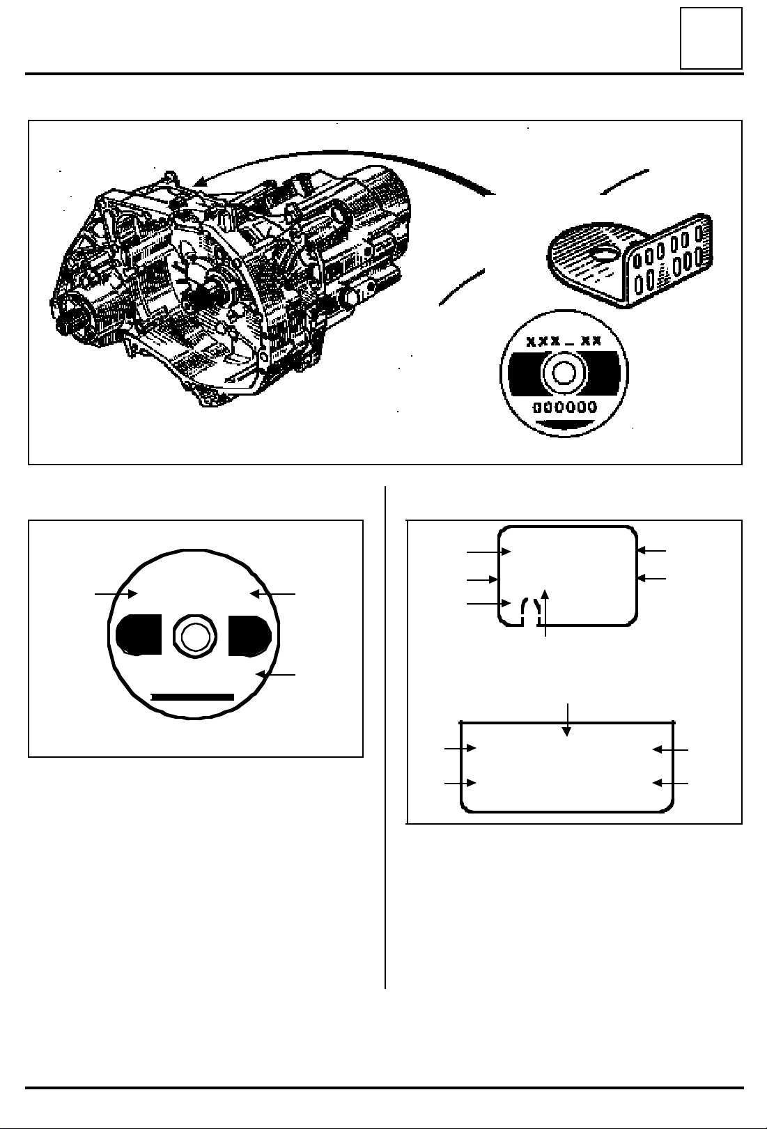
MANUAL GEARBOX
Identification
21
DI2117-2
st
1
assembly
TYPE
A
XXX - XX
000000
90775
At A : Gearbox type.
At B : Gearbox suffix.
At C : Production number.
B
C
DI2117-1
nd
2
assembly
000JB0
D C
E
A
D
At A : Gearbox type.
At B : Gearbox suffix.
At C : Production number.
At D : Manufacturing factory.
At E : A notch if the gearbox is assembled
At F : Homologation letter.
At G : Letter preceding production numbers
X
X00000
G
F
000JB0 AA
X 0 0 0 0 0 0 0
with a C or E engine.
greater than 999 999.
BA
B
C
90 775
Following saturation of the production numbering system on the identification plate of JB and JC gearboxes,
a new numbering system will be in force for numbers greater than 999 999 (at C).
These will have a letter in place of the first number, (at G).
21-2
Page 5
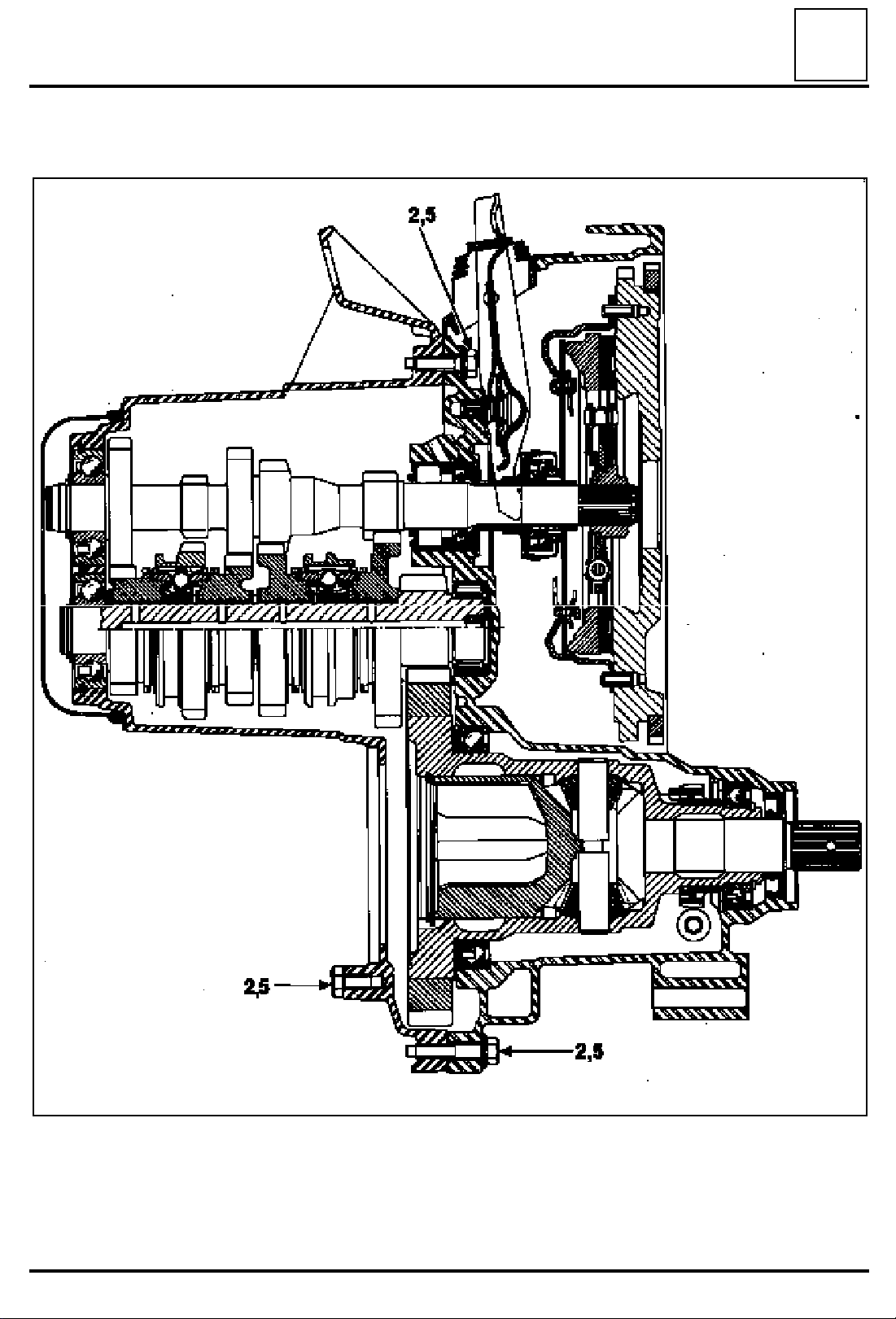
MANUAL GEARBOX
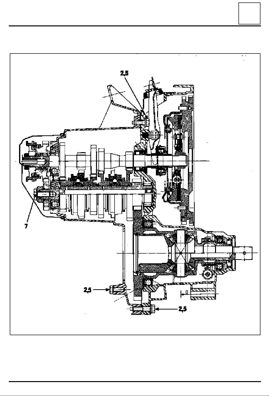
Cross-section and Tightening torques (in daN.m)
21
JB 4-speed manual gearbox - 1
st
assembly
21-3
85680R
Page 6
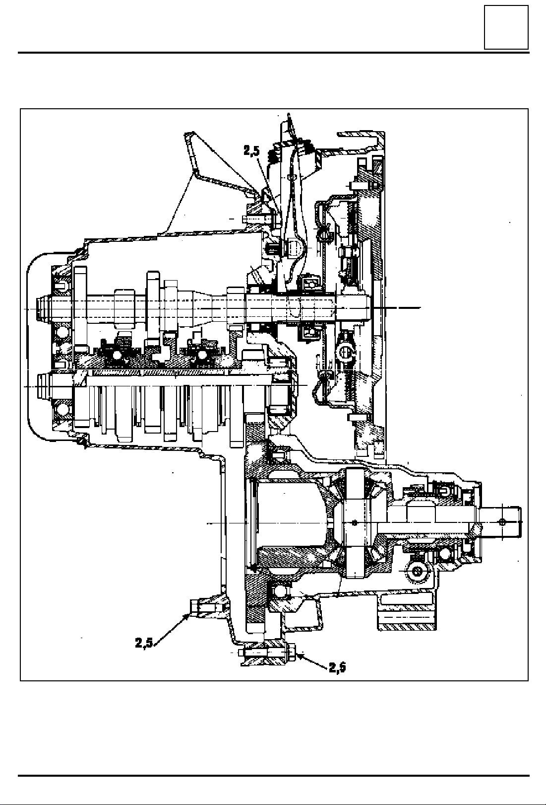
MANUAL GEARBOX
Cross-section and Tightening torques (in daN.m)
21
JB 4-speed manual gearbox - 2
nd
assembly
21-4
88519R
Page 7
MANUAL GEARBOX
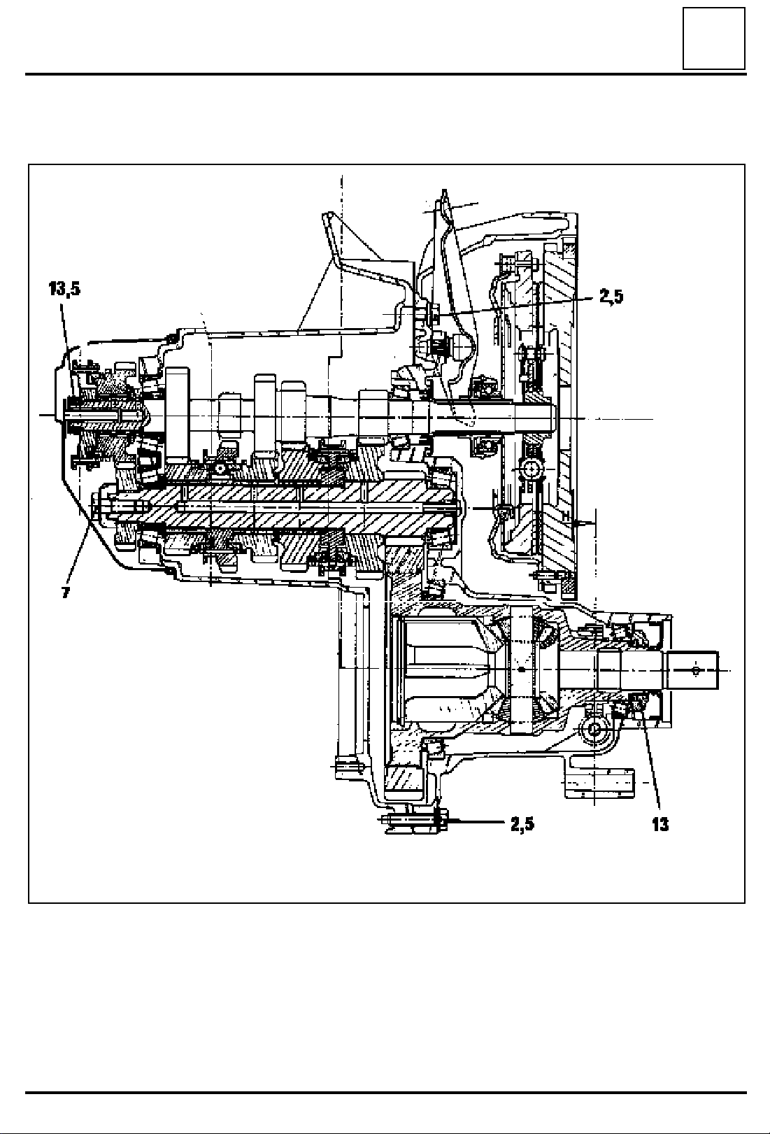
Cross-section and Tightening torques (in daN.m)
5-speed manual gearbox
21
21-5
90674R1
Page 8
MANUAL GEARBOX
Cross-section and Tightening torques (in daN.m)
JC 5-speed manual gearbox
21
DI2126
21-6
Page 9
MANUAL GEARBOX
Tightening torques
Tightening torques
21
Description
Bolt securing the mechanism housing to the clutch housing 2.5
Output shaft bolt 7
Input shaft nut 13.5
Body (5th gear detent) 2
Rear cover bolt 2.5
Thrust pad guide tube bolt 2.5
Drain plug 2.5
Reversing lights switch 2.5
Bolt securing the left-hand drive shaft bellows 2.5
Bolt securing the gearbox to the cylinder block 5
Torque in
daN.m
21-7
Page 10

MANUAL GEARBOX
Gears
These tables group together all of the gears
available for JB gearboxes.
JB0 gear table
Gear 1st 2nd 3rd 4th Reverse
21
11
A
B
C
Gearbox suffixes Vehicles Differential ratio
000
003 L 422
004
-39
11
-41
11
-41
L 421 - L 422 - L 425
B/C/S 371
B/C 372
C 37S
L 422
B/C 372
16
-33
19
-39
21
-43
15
--
58
14
--
59
15
--
58
25
-33
25
-33
28
-37
Speedometer drive
gear
21
--
19
21
--
19
21
--
19
31
-28
31
-28
31
-28
11
-- 26
39
11
-- 26
39
11
-- 26
39
Gear
A
A
A
006 L 422 - L423
008
009 B/C/S 404
010 F 404
011
014 F 400
L422
B/C 372
L 421 - L 422 - L 423
L425 - L 426
B/C/S 371
B/C 372 - B/C 375
F 401 - F 40H
14
--
59
15
--
58
19
--
59
16
--
57
15
--
58
14
--
63
21
--
19
21
--
19
21
--
20
21
--
19
21
--
19
21
--
19
B
B
B
B
B
B
21-8
Page 11

MANUAL GEARBOX
Rapports
21
Gearbox suffixes Vehicles Differential ratio
L 422 - L 423
016
017
018 F 401
019
021 B 372 - B 401
022 F 400
023
024 F 404
025 F 401
028
029 B/C/S 401
031 B/C/S 571
032
033 F 401 - F 404 - F 40H
034 B/C 57N
035 F 40F
036 F 40F
038 F 404
B 372 - B 373
B/C 401
B/C/L 531 - B/C/L 532
B/C/L 537 - B/C/L 53P
B/C/L 53R
B/C/L 53H
K/S 480
B/C 37S
F 401 - F 40H
B/C/L/S 530
B/C 400
F 401 - F 40T
B/C 572
C 57A
14
--
59
16
--
57
15
--
58
15
--
56
14
--
59
14
--
63
15
--
58
16
--
57
15
--
58
15
--
58
17
--
56
16
--
55
16
--
57
15
--
58
16
--
57
15
--
61
15
--
61
15
--
61
Speedometer drive
gear
21
--
19
21
--
19
21
--
19
21
--
19
21
--
19
21
--
19
21
--
19
21
--
19
21
--
19
21
--
20
21
--
20
21
--
20
21
--
20
21
--
19
21
--
19
21
--
19
21
--
20
21
--
19
Gear
B
C
B
C
C
C
C
C
C
C
C
C
C
C
C
C
C
C
21-9
Page 12

MANUAL GEARBOX
Gears
JB1 gear table
Gear 1st 2nd 3rd 4th 5th Reverse
21
11
A
B
C
D
E
F
G
-39
11
-41
11
-39
11
-41
11
-41
11
-41
11
-34
16
-33
16
-33
16
-33
19
-39
21
-43
22
-41
22
-41
25
-33
26
-33
25
-33
25
-33
28
-37
28
-37
28
-37
31
-28
31
-28
31
-28
30
-29
30
-29
30
-29
30
-29
33
-25
37
-27
37
-27
34
-27
39
-31
41
-31
39
-31
11
-- 26
39
11
-- 26
39
11
-- 26
39
11
-- 26
39
11
-- 26
39
11
-- 26
39
11
-- 26
39
M
11
H
I
J
K
L
N
-41
11
-41
11
-37
11
-41
11
-37
11
-37
11
-41
21
-43
21
-43
22
-41
21
-43
22
-41
22
-41
21
-43
28
-37
28
-39
28
-37
28
-39
28
-37
28
-37
28
-37
30
-39
34
-35
30
-39
34
-35
30
-29
30
-39
30
-29
41
-31
34
-28
39
-31
39
-32
41
-31
39
-32
39
-32
11
-- 26
39
11
-- 26
39
11
-- 26
39
11
-- 26
39
11
-- 26
39
11
-- 26
39
11
-- 26
39
11
O
-41
21
-43
28
-37
30
-29
41
-31
11
-- 26
39
21-10
Page 13

MANUAL GEARBOX
Gears
21
Gearbox suffixes Vehicles Differential ratio
L 421 - L 422 - L 423
001
002 L 421
003 L 422 - L 423
004
005
006
007
008 B/C 373
009
011
012 B 373
013 B/C/S 404
014
015
016
018
019
B/C 371 - B/C 372
B/C 373
L 421 - L 424
B/C/S 374
L 422 - L 423
B/C 372 - B 373
L 424
B/C 374
L 424
B/C 374
L 421 - L 422 - L 423
L 424 - L 42A - L 42C
L 42R - L 42S
B/C 371 - B/C 372
B/C/S 373
B/C 37A - B/C 37C
B 37R - B/S 37S
L 424 - B/C/S 374
F 401 - F 402 - F 407
F 40H
L 424
B/C 374
L 424
B 374
L 422 - L 423
B/C 372 - B 373
B 374
L 423
B/C 373
B/C 402
L 424
B/C/S 374
F 404
14
--
59
15
--
58
15
--
58
15
--
58
14
--
59
15
--
58
14
--
59
14
--
59
15
--
61
15
--
58
15
--
61
17
--
56
15
--
58
16
--
57
17
--
56
14
--
63
15
--
58
Speedometer drive
gear
21
--
19
21
--
19
21
--
19
21
--
19
21
--
19
21
--
19
21
--
19
ELECTRONIC
SPEEDOMETER
21
--
19
21
--
19
ELECTRONIC
SPEEDOMETER
21
--
20
21
--
19
21
--
19
21
--
19
21
--
19
21
--
19
Gear
A
A
B
C
A
C
C
A
D
E
E
E
E
E
D
D
D
21-11
Page 14

MANUAL GEARBOX
Gears
21
Gearbox suffixes Vehicles Differential ratio
16
020 B/C 404
021 F 404
022 B 402
F 401 - F 402 - F 407
023
024 B/C 53
025
026 F 402
027
028 B/C/S 404
029
030
031 B/C/S 404
032 F 404
033
034
035
F 40H - F 40M
B/C/L 532
L 423 - L 424 - L 42A
L 42C - L 42S
B/C 373 - B/C 37A
B 37C
F 401
B/C/L/S 537
B/C/L/S 530
B/C/L/ 53A
B/C/L 53R
F 402
B/L 53H
B 402
B/C 480
K/S 480
B/C/L 53G
F 404
L 424
B/C/S 374
L 423
B 373
B/C/L 531
B/C/L 53P
B/C/S 401
B/C 403
B/C/S 407
B 40H
--
57
15
--
61
15
--
61
15
--
58
15
--
57
15
--
61
15
--
58
15
--
58
17
--
56
15
--
61
15
--
58
16
--
57
15
--
61
14
--
63
16
--
57
16
--
55
Speedometer drive
gear
21
--
20
21
--
19
21
--
19
21
--
19
21
--
19
21
--
19
21
--
19
21
--
19
21
--
20
21
--
19
21
--
19
21
--
20
21
--
19
21
--
19
21
--
19
21
--
20
Gear
D
D
D
E
E
E
D
E
E
E
E
E
E
E
E
E
21-12
Page 15

MANUAL GEARBOX
Gears
21
Gearbox suffixes Vehicles Differential ratio
B/C 400
036
037
038
039 B/C 570
041 X 57
042 X 40
043
044 F 401 - F 40H
045
046
047 F 40F
048
049 F 40A
050 F 40F
051 F 407
052 C06 3
053 X 57
054 BA0 E
F 401
F 40T
C 402
B/C/S 40F
B/C 402
B/C 40F
B/C/S 571
B/C/S 572 - B/C 573
B/C 57A - B/C 57B
B/C 57J - B/C 57L
B/C 57T
B/C 57N
B/C 57P
B/C/S 572
B/C/S 57A
B/C/S 57R
F 40A - F 40U
F 40V - F 40Y
15
--
61
17
--
56
16
--
57
14
--
59
14
--
59
15
--
61
16
--
57
15
--
58
14
--
59
14
--
59
14
--
63
14
--
63
14
--
63
14
--
63
14
--
59
15
--
56
14
--
59
15
--
61
Speedometer drive
gear
21
--
20
21
--
20
21
--
20
21
--
20
21
--
20
21
--
20
21
--
20
21
--
19
21
--
19
21
--
20
21
--
19
21
--
19
21
--
20
21
--
20
21
--
19
21
--
20
21
--
20
21
--
19
Gear
E
E
E
E
F
F
E
E
F
G
E
E
E
E
E
H
F
E
21-13
Page 16

MANUAL GEARBOX
Gears
21
Gearbox suffixes Vehicles Differential ratio
15
057 X 06
061
066 X 57
068
069
070 X 53 - F 40
071 X 57
072 X 57
074 X 57
080 X 57
082 X 57
085 B/C 57
087 B/C 57
095
097 JA0 E
099
100 F 40
104 X 57
X 06
with AC
BA0 A - BA0 U
DA0
X 06
with AC
BA0 E
SA0 E
BA0
DA0
--
56
15
--
58
15
--
56
15
--
56
15
--
58
15
--
61
16
--
57
15
--
59
15
--
58
15
--
56
16
--
57
15
--
56
15
--
56
15
--
61
14
--
63
15
--
58
15
--
61
17
--
56
Speedometer drive
gear
21
--
20
21
--
20
21
--
20
21
--
19
21
--
20
21
--
19
21
--
20
21
--
19
21
--
19
21
--
20
21
--
20
21
--
20
21
--
19
21
--
19
21
--
18
21
--
19
21
--
19
21
--
20
Gear
H
I
I
E
E
E
E
F
E
I
E
I
E
E
K
E
E
E
21-14
Page 17

MANUAL GEARBOX
Gears
21
Gearbox suffixes Vehicles Differential ratio
17
105 X 57
106
107 F 40
109 F 40
110 F 40
111
119
120
123
124
126 F 40
129
130
131 X 57
132 C 06
137 C 06
138 B/C 57
140 X 57
BA0
DA0
X 53
X 48
BA0 L
BA0 F
BA0 L
BA0 F
BA0 L
BA0 P
BA0 L
BA0 F
BA0
SA0
BA0 E
JA0 E
--
56
15
--
58
15
--
58
15
--
58
16
--
57
16
--
57
15
--
58
15
--
58
15
--
58
15
--
58
16
--
61
15
--
56
14
--
63
17
--
56
15
--
56
15
--
56
15
--
56
15
--
56
Speedometer drive
gear
21
--
20
21
--
19
21
--
19
21
--
19
21
--
19
21
--
19
21
--
19
21
--
19
21
--
19
21
--
19
21
--
19
21
--
19
21
--
18
21
--
20
21
--
20
21
--
20
21
--
20
21
--
20
Gear
E
E
E
E
D
D
J
J
J
J
E
E
K
H
L
L
K
I
21-15
Page 18

MANUAL GEARBOX
Gears
21
Gearbox suffixes Vehicles Differential ratio
14
141 X 57
142 XA0
143 XA0
144 X06
145 X06
164 XA0
165 XA0
166 B/DA0
167 B/DA0
168 XA0
169 XA0
170 BA0
--
59
15
--
56
15
--
56
15
--
58
15
--
58
15
--
58
15
--
58
15
--
58
15
--
58
15
--
56
15
--
56
15
--
58
Speedometer drive
gear
21
--
20
21
--
19
21
--
19
21
--
20
21
--
20
21
--
19
21
--
19
21
--
19
21
--
19
21
--
19
21
--
19
21
--
19
Gear
F
E
E
M
M
M
M
M
M
O
O
N
21-16
Page 19

MANUAL GEARBOX
Gears
JB2 gear table
Gear 1st 2nd 3rd 4th Reverse
21
11
A
B
Gearbox suffixes Vehicles Differential ratio
000
001 X53
002
004 X48
005 F40
-41
11
-41
K/L/S 481
K/L 482
K/L 48M
B/K/L/S 481
B/K/L 482
K/L 48M
19
-39
21
-43
17
--
56
16
--
55
17
--
56
17
--
56
17
--
56
25
-33
28
-37
Speedometer drive
gear
21
--
19
21
--
19
21
--
19
21
--
19
21
--
19
31
-28
31
-28
11
-- 26
39
11
-- 26
39
Gear
A
B
B
A
B
21-17
Page 20

MANUAL GEARBOX
Gears
JB3 gear table
Gear 1st 2nd 3rd 4th 5th Reverse
21
11
A
B
C
D
E
F
G
-41
11
-34
11
-41
11
-41
11
-34
11
-34
11
-41
19
-39
19
-35
21
-43
22
-41
22
-41
19
-35
21
-43
25
-33
25
-33
28
-37
38
-37
28
-37
25
-33
28
-39
30
-29
30
-29
30
-29
30
-29
30
-29
30
-29
34
-35
34
-27
33
-25
39
-31
41
-31
41
-31
39
-31
34
-28
11
-- 26
39
11
-- 26
39
11
-- 26
39
11
-- 26
39
11
-- 26
39
11
-- 26
39
11
-- 26
39
M
11
H
I
K
L
N
O
-34
11
-34
11
-34
11
-34
11
-41
13
-45
11
-41
22
-41
19
-35
19
-35
22
-41
21
-43
21
-43
21
-43
28
-37
25
-33
25
-33
28
-37
28
-37
28
-37
28
-39
34
-35
30
-29
30
-29
30
-29
30
-29
30
-29
34
-35
34
-28
34
-27
41
-31
39
-41
41
-31
41
-31
39
-32
11
-- 26
39
11
-- 26
39
11
-- 26
39
11
-- 26
39
11
-- 26
39
11
-- 26
39
11
-- 26
39
11
P
-34
22
-41
28
-37
30
-29
42
-31
11
-- 26
39
21-18
Page 21

MANUAL GEARBOX
Gear
21
Gearbox suffixes Vehicles Differential ratio
001
002
003 B/C 376
005 X 42
006 X 42
008 X 42
009 C 405
010
011
012 B 376
013
014 C 405
017
019 C 409
020 X 42
021
022 K/L 482
B/C 37F - B/C 376
L 426 - L 42F
B/C 375
L 425
L 426 - L 42F
L 42L - L 42N
B/C 376 - B/C 37F
B/C 37G - B/C 37L
B 37M - C 37N
K/L/S 481 - K/L/S 482
K/L 48F
B/C 375
L 425
B 376
L 426
B 376
L 481 - L 482
K/L 48E - K/L 48J
K/L 48N
L 42E
B/C 37E
16
--
57
15
--
61
16
--
57
17
--
56
16
--
57
15
--
61
15
--
56
16
--
57
15
--
61
16
--
57
15
--
61
15
--
56
15
--
61
15
--
58
15
--
61
14
--
59
15
--
58
Speedometer drive
gear
21
--
19
ELECTRONIC
SPEEDOMETER
ELECTRONIC
SPEEDOMETER
21
--
19
21
--
19
21
--
19
ELECTRONIC
SPEEDOMETER
21
--
19
ELECTRONIC
SPEEDOMETER
ELECTRONIC
SPEEDOMETER
21
--
19
ELECTRONIC
SPEEDOMETER
21
--
19
21
--
20
21
--
19
21
--
19
21
--
19
Gear
A
B
A
A
A
A
B
A
C
B
A
C
A
B
B
B
B
D
B
A
21-19
Page 22

MANUAL GEARBOX
Gears
21
Gearbox suffixes Vehicles Differential ratio
16
023 B/C 408
024
026
027
028
029 X 53
030 X 53
031
032 C 405
033 C 409
034 B/C 408
B/C 40G
B/C 40K
C 376 - B/C 37D
B/C 37F - B 37H
B/C 37L - C 37N
L 42D - L 42L
L 42F - L 42N
K/L/S 481 - K/L/S 482
K/L 48F - K/L 48M
B/K/L/S 481
B/K/L/S 482
B/K/L/ 484
B/K/L/ 48E - K 48F
B/K/L 48J
L/B 48L - K/L 48M
K/C 48N
B/C/L 533 - L 53B
B/C/D 53C
B/C/L 53M
L 42D - L 42F
L 42N - C 37D
B/C 37F - B 37H
C 37N
B/K/L/S 481
B/K/L/S 482
K/L 48E
B/K/L 48F
B/K/L/S 48H
K/L 48M
B/C/L 533
B/C/L/S 534
B/C/L 53B
B/C 53E
B/C/L 53C
B/C/L/S 53J
B/K 482
B 533
B/L 536
--
57
16
--
57
16
--
57
15
--
61
16
--
57
15
--
61
14
--
59
15
--
58
15
--
56
15
--
58
16
--
57
Speedometer drive
gear
21
--
20
21
--
20
21
--
19
21
--
19
21
--
19
21
--
19
21
--
19
21
--
19
ELECTRONIC
SPEEDOMETER
21
--
20
21
--
20
Gear
A
B
A
D
C
C
B
C
B
E
C
21-20
Page 23

MANUAL GEARBOX
Gears
21
Gearbox suffixes Vehicles Differential ratio
035
036
037
038
041
044
045 B/C 574
046
047 B/L 57B
048 C 575 - C 57D
050 F 40N - F 40P
051
059 X 53 - X 48
060 X 53 - X 48
062 X 42 - X 48
064 X 57
066 X 57
067 X 53
B/C 40G
B/C 40K
L 425
B/C 375
L 42E
B/C 37E
B/C/D/L 53C
B/C/L 53F
B 376
L 426
K/L 48U
B/C/S 576
B/C/S 57L
B/C/L 539
B/C/D/L 53D
B/C 574 - B/C 57C
B/C 57U
B/C/L 539
B/C/D/L 53D
16
--
57
15
--
61
14
--
59
15
--
61
17
--
56
15
--
61
16
--
55
15
--
58
16
--
55
14
--
59
15
--
58
15
--
61
15
--
61
16
--
57
14
--
59
17
--
56
15
--
58
16
--
55
Speedometer drive
gear
21
--
20
ELECTRONIC
SPEEDOMETER
21
--
19
21
--
19
21
--
20
21
--
19
21
--
20
21
--
20
21
--
19
21
--
19
21
--
19
21
--
19
21
--
19
21
--
19
21
--
19
21
--
20
21
--
20
21
--
19
Gear
E
B
E
C
C
F
C
D
C
F
C
F
D
C
E
C
E
C
21-21
Page 24

MANUAL GEARBOX
Gears
21
Gearbox suffixes Vehicles Differential ratio
15
078 X 57
080
083 X 53
097 F 40
100 B 56B
101 B 56B
102 B 56B
103 X 57
106 BA0 G
108 B/K 56
113 K 56
132 K 56
140 X 56
142
143
170
BA0
JA0
BA0
SA0
BA0
DA0
BA0
LA0
--
61
15
--
61
15
--
61
16
--
57
15
--
58
16
--
57
15
--
61
17
--
56
15
--
61
15
--
58
16
--
57
15
--
58
15
--
56
15
--
59
15
--
61
15
--
61
Speedometer drive
gear
21
--
19
21
--
18
21
--
19
21
--
19
21
--
18
21
--
18
22
--
18
21
--
20
21
--
19
21
--
18
21
--
18
21
--
18
21
--
18
21
--
18
21
--
19
21
--
18
Gear
E
M
H
C
G
M
G
C
P
O
M
G
M
S
P
C
21-22
Page 25

MANUAL GEARBOX
Gears
JB4 gear table
Gear 1st 2nd 3rd 4th Reverse
21
11
A
Gearbox suffixes Vehicles Differential ratio
000
001 X 400
002 X 401
003 X 40F
004
005 B/C 53
006 B/C 53
007 B/C 53
008 X 57
-41
L 421 - L 425
F 40F
B/C 537
C 375
X 40F
X 571
19
-39
15
--
58
15
--
58
17
--
56
16
--
57
16
--
55
16
--
57
16
--
57
15
--
58
16
--
57
25
-33
Speedometer drive
gear
21
--
19
21
--
20
21
--
20
21
--
20
21
--
20
21
--
19
21
--
19
21
--
19
21
--
20
31
-28
11
-- 26
39
Gear
A
A
A
A
A
A
A
A
A
21-23
Page 26

MANUAL GEARBOX
Gears
JB5 gear table
Gear 1st 2nd 3rd 4th 5th Reverse
21
11
A
B
Gearbox suffixes Vehicles Differential ratio
000
001
002 B/C 403
003
004 B/C 400
005
006
007
008 B/C 40F
009
010 B/C 572
015 B/C/S 572
-41
11
-34
L 421 - L 422
B/C/L 42S
B/C 371 - S 372
B/C/S 375
B/L/S 530
B/C/S 401
B/C 403 - B/C 407
B/C 40H - B/C 40J
B/C 40M
B/C 402 - B/C 407
B/C/S 40F
B/C 402 - B/C 40F
B/C/S 571
B/C/L 531
C 53P
F 401
F 40 H
L 422 - L 423
B/S 372
B 373
19
-39
19
-35
25
-33
25
-33
15
--
61
16
--
55
15
--
61
17
--
56
15
--
61
16
--
57
16
--
57
15
--
58
15
--
58
15
--
61
16
--
57
14
--
59
30
-29
30
-29
Speedometer drive
gear
21
--
19
21
--
20
21
--
20
21
--
20
21
--
20
21
--
20
16
--
57
21
--
19
21
--
20
21
--
19
21
--
20
21
--
20
34
-27
33
-25
11
-- 26
39
11
-- 26
39
Gear
A
A
B
A
A
A
A
A
A
A
A
A
21-24
Page 27

MANUAL GEARBOX
Gears
These tables group together all of the gears
available for
Gear 1st 2nd 3rd 4th 5th Reverse
JJJJCCCC5555
gearboxes.
21
11
A
B
C
D
E
F
G
-41
11
-41
11
-41
11
-34
11
-41
11
-41
11
-37
21
-43
21
-43
22
-41
22
-41
21
-43
21
-43
22
-41
28
-37
28
-37
28
-37
28
-37
28
-37
28
-37
28
-39
35
-34
31
-29
35
-34
34
-35
35
-34
35
-34
31
-34
41
-31
42
-31
41
-31
39
-31
42
-31
39
-31
37
-33
11
-- 26
39
11
-- 26
39
11
-- 26
39
11
-- 26
39
11
-- 26
39
11
-- 26
39
11
-- 26
39
11
H
I
-37
11
-41
22
-41
21
-43
28
-37
28
-39
34
-35
31
-34
39
-32
39
-32
11
-- 26
39
11
-- 26
39
21-25
Page 28

MANUAL GEARBOX
Gears
21
Gearbox suffixes Vehicles Differential ratio
17
002 X 53K
004 B 56C
005 X 56
014 X 57
016 B 56C
017 X 56
022 B 56C
024 B 56C
025 XA0
026 JA0
028 B 56
029 B 56
032 B/K 56
033 B/K 56
036 K/S 56
037 B/K 56
038 B/K 56
039 B/K 56
--
56
15
--
58
15
--
56
15
--
61
15
--
61
15
--
61
15
--
61
15
--
58
15
--
61
15
--
61
15
--
61
15
--
61
15
--
58
15
--
61
15
--
56
15
--
61
15
--
61
15
--
61
Speedometer drive
gear
21
--
19
21
--
18
21
--
18
21
--
29
22
--
18
22
--
18
22
--
18
21
--
18
21
--
18
21
--
18
21
--
18
21
--
18
21
--
18
22
--
18
21
--
18
21
--
18
21
--
18
21
--
18
Gear
A
B
C
D
E
E
B
F
H
F
G
G
F
E
F
G
G
G
21-26
Page 29

MANUAL GEARBOX
Gears
21
Gearbox suffixes Vehicles Differential ratio
15
040 B/K 56
044 X 56
045 X 56
047 B/K 56
048 B/K 56
052 XA0
053 XA0
066 JA0
067 JA0
075 B 56
076 B 56
--
61
15
--
58
15
--
61
15
--
61
15
--
61
17
--
56
15
--
61
15
--
61
15
--
61
15
--
61
15
--
61
Speedometer drive
gear
21
--
18
21
--
18
22
--
18
22
--
18
22
--
18
21
--
29
21
--
18
22
--
18
22
--
18
22
--
19
22
--
18
Gear
G
C
B
G
G
A
H
I
E
H
H
21-27
Page 30
MANUAL GEARBOX
Capacity - Lubricants
21
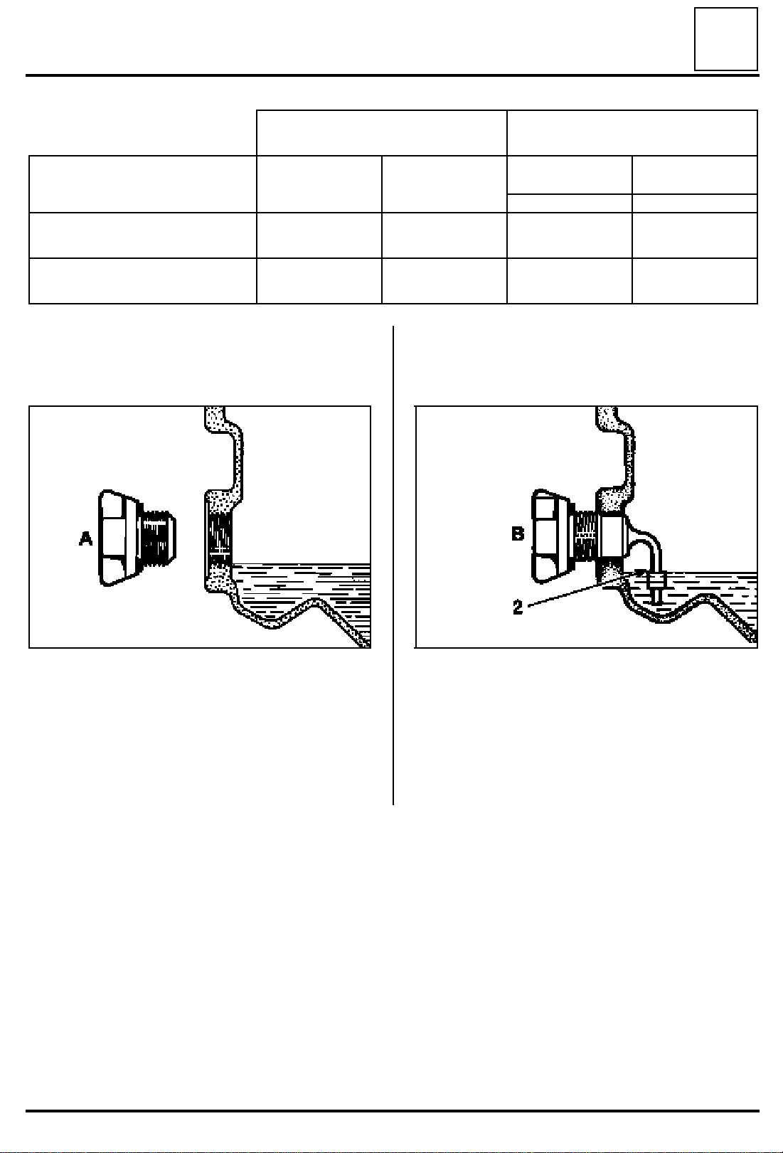
CAPACITY (in litres)
Plug with no dipstick:
normal level
Plug with dipstick:
low level
Plug with no dipstick:
From September 89
LLLLEEEEVVVVEEEELLLL CCCCHHHHEEEECCCCKK
KK
Plug (A) with no dipstick Plug (B) with dipstick
JB0
JB2
JB4
JB4
5-speed gearbox4-speed gearbox
3.25
2.8 JB5 2.90
2.8 JB5 2.90
JB1
JB3
JC5
3.40
3.1
92081R DI2127
Fill to the level of the opening. Wipe the dipstick section.
Replace the plug without tightening it, dipstick
directed downwards.
Remove the plug, the level should be on the boss
(2).
21-28
Page 31

MANUAL GEARBOX
Special points
21
Gearboxes
JB0 4 forward gears
JB2
JB4 1 reverse gear
JB1 5 forward gears
JB3
JB5 1 reverse gear
JC5
are fitted with BORG-WARNER synchronisers.
GGGGEEEEAAAARRRR GGGGRRRRIIIIDD
DD
R 1 3 5
2 4
B.V. JB
DDDDIIIIFFFFFFFFEEEERRRREEEENNNNTTTTIIIIAAAALL
The differential cannot be adjusted.
Two types of bearing assembly are used, either
with balls or with tapered rollers.
SSSSHHHHAAAAFFFFTTTTSS
The lip seal and the guide tube bearing rollers are
in direct contact with the input shaft.
If the mating surface is imperfect, the input shaft
must be changed.
The hubs are fitted free on the output shaft and
their sideways movement is checked by thrust
washers.
The reverse gear is sold fitted to the shaft.
The thrust pad guide tube can only be removed
following removal of the clutch housing.
The use of 037M00 equipment simplifies the
operation, refer to the procedure on page 21-92.
LL
SS
To engage reverse gear, raise the locking ring (A)
and move the lever.
DI2128
MMMMAAAATTTTCCCCHHHHEEEEDDDD PPPPAAAARRRRTTTTSS
Synchroniser hubs and sliding gears.
SS
IIIINNNNTTTTEEEERRRRNNNNAAAALLLL CCCCOOOONNNNTTTTRRRROOOOLLLLSS
The fifth gear fork has two plastic pads which are
greased via a mechanism housing channel.
The pins are fitted on the selection finger one
after the other.
SSSSPPPPEEEECCCCIIIIAAAALLLL FFFFEEEEAAAATTTTUUUURRRREEEESSSS OOOOFFFF TTTTHHHHEEEE JJJJCCCC5555 GGGGEEEEAAAARRRRBBBBOOOOXX
Adoption of tapered bearings on the input and
output shafts.
Setting of the input and output lines.
Guide tube with double sealing on the housing
and clutch shaft which can be removed without
opening the gearbox.
Strengthening of the mechanism and clutch
housings.
Widening of the teeth.
SS
XX
In all cases, it is advisable to mark the sliding gears
in relation to the hubs and to mark the hubs in
relation to the shafts.
21-29
Page 32

5th gear fixed gear mounting
MANUAL GEARBOX
Modifications
21
st
1
assembly
nd
2
assembly
rd
3
assembly
DI2133 87180R7
th
4
assembly
* Glue using "Loctite Frenbloc"
87180-1R86322R2
Special features:
Reduction of the tapping depth at the end of the
output shaft into which the 5th gear fixed gear
mounting bolt is inserted.
It is essential to fit a 27mm long bolt.
21-30
Page 33

MANUAL GEARBOX
Modifications
Widening of the teeth of the 5th gear on JB1/JB3 gearboxes.
21
Fixed gears
Idle gears
Thrust washer
dimension A
(mm)
1st assembly 5.5 14.1 13.7 13 237.3
nd
2
assembly 7.5 12.1 15.7 15 239.3
* Only the hub dimension changes, the sliding gear remains identical for both assemblies.
** Following the modification to the length of the fork shaft, the position of the fork pads changes by 2 mm.
* Hub
Dimension B
JB1 and JB3 27 teeth
JB3 25 teeth
JB1 and JB3
JB3 33 teeth
Idle gear
Dimension C
(mm)
(mm)
34 teeth
Fixed gear
Dimension D
(mm)
** Fork shaft
Dimension E
(mm)
21-31
87180R3
Page 34

MANUAL GEARBOX
Consumables
Type Packaging Part N° Component
Clutch fork pad.
Clutch fork pivot.
Molykote "BR2" 1 Kg box 77 01 421 145
Loctite 518 24 ml syringe 77 01 421 162 Housing assembly surfaces.
LLLLooooccccttttiiiitttteeee FFFFRRRREEEENNNNBBBBLLLLOOOOCC
CC
24 cc flask 77 01 394 071
Clutch thrust pad guide tube
Right-hand sun wheel grooves.
5th gear fixed gear and hub.
Input and output shaft nut.
Output shaft bolt.
21
RRRRHHHHOOOODDDDOOOORRRRSSSSEEEEAAAALLLL 55556666666611
EEEEXXXX:::: CCCCAAAAFFFF 4444////66660000 TTTTHHHHIIIIXXXXOO
11
Ends of the roll pins on the drive shaft.
OO
100 g tube 77 01 404 452
Switch threads.
Parts which must always be changed
When they have been removed:
- the lip seals,
- the O-rings,
- the stop rings,
- the thrust pad guide tube,
- the differential ball bearings,
- the speedometer crown wheel (JB2 - JB3,
differential fitted on tapered bearings),
- the speedometer shaft and gear,
- the roll pins,
- the output shaft and differential nuts,
- the rings under the gears,
- the input and output shaft bearing circlips.
21-32
Page 35

MANUAL GEARBOX
Special tools
21
Figure
90723S
90722S
77743S1
Procedures
reference
B. Vi. 22-01 00 01 216 401 Bearing extractor body.
B. Vi. 28-01 00 01 227 301 Bearing extractor with claws.
B. Vi. 31-01 00 01 259 401
Part
number
Description
Set of 3 pins for fitting the 5 mm diameter roll
pins.
84519-1S
86095S
86096-1S
86097S
B. Vi. 902-01 00 00 090 201
B. Vi. 945 00 00 094 500
B. Vi. 946 00 00 094 600
B. Vi. 947 00 00 094 700
Tool for fitting circlips to the input and output
shafts.
Mandrel for fitting the sun wheel seal.
Mandrel for fitting the snap ring on the sun
wheel.
Mandrel for fitting the bearings in the
mechanism housing.
21-33
Page 36

MANUAL GEARBOX
Special tools
21
Figure
86098S
90664S
87213S
Procedures
reference
B. Vi. 949 00 00 094 900
B. Vi. 950-02 00 00 095 002
B. Vi. 1 000 00 00 100 000
Part
number
Description
Fork roll pins fitting and removal tool.
Adaptable gearbox stand on the Desvil stand.
Extractor for the 5th fixed gear on the output
shaft, use with B.Vi. 22-01.
87571S
86097S
90594S
90592S
B. Vi. 1 007 00 00 100 700 Claws for B.Vi. 28-01.
B. Vi. 1 030 00 00 103 000
B. Vi. 1 057 00 00 105 700
B. Vi. 1 058 00 00 105 800
Mandrel for fitting bearings into mechanism
housing.
Tool for inhibiting rotation of the differential,
JB and JC gearboxes.
Mandrel for fitting the output seal on JB and
JC gearboxes, differential end.
21-34
Page 37

MANUAL GEARBOX
Special tools
21
Figure
90588S
91218-1S
93229S
Procedures
reference
B. Vi. 1 059 00 00 105 900
B. Vi. 1 078 00 00 107 800
B. Vi. 1 162 00 00 116 200
Part
number
Description
Rings for fitting differential bearings, JB / JC
gearbox.
Tool for fitting the crown wheel sensor
mounting spring on the JB 3 gearbox.
Mandrel for changing the control shaft
bearing rings.
93190S
93461S
84328S
B. Vi. 1 170 00 00 117 000
B. Vi. 1 175 00 00 117 500 5th fixed gear mounting bolt.
Emb. 880 00 00 088 000 Clutch fork roll pin extractor (JC gearbox).
Emb. 1163 00 00 116 300 Thrust pad guide tube extraction and fitting
Extractor for the 5th gear hub on the input
shaft.
tool (JC gearbox).
93068S1
21-35
Page 38

MANUAL GEARBOX
Special tools
21
Figure
93226S1
93407S1
69306-1S
Procedures
reference
B. Vi. 1 161 00 00 116 100
B. Vi. 1 165 00 00 116 500
Roul. 15-01 00 01 331 601 Shaft protective end piece, internal diameter
Part
number
Description
Dial gauge support plate and pre-load presetting washers.
Tool for extracting the output shaft bearing
on the clutch-differential housing.
16 mm.
21-36
Page 39

MANUAL GEARBOX
Gearbox repair
Parts must be removed and handled on a work bench with a covering which protects against impact
(rubber or thick plastic).
21
SSSSEEEEPPPPAAAARRRRAAAATTTTIIIINNNNGGGG TTTTHHHHEEEE HHHHOOOOUUUUSSSSIIIINNNNGGGGSS
Remove the thrust pad and the fork from inside
the housing.
Special features of the JC5 gearbox
Remove the two thrust pad guide tube mounting
bolts.
SS
Extract the guide tube lip seal carefully using 2
screwdrivers.
::
NNNNOOOOTTTTEEEE::
The guide tube-lip seal assembly must be changed
whenever it is removed.
All types:
Remove the bolts located inside the clutch
housing.
Fit tool Emb. 1163 on the guide tube and tighten
it.
To this, tighten tool Emb. 880 and extract the
guide tube.
92949R
92950R
88482R
If necessary, remove the centring pins placed at
(D) and (E).
21-37
Page 40

MANUAL GEARBOX
Secure the gearbox to the adaptable stand
B. Vi. 950-02 on the DESVIL base.
Gearbox repair
92958R1
21
90664R
::
NNNNOOOOTTTT EEEE::
In order to allow removal of the differential fitted
on tapered bearings (JB2 - JB3), stand B. Vi. 950-
02 must be used or stand B. Vi. 950-01 must be
modified.
Saw the support plate B Vi. 950 as shown below.
Remove the rear housing. This must be removed
in the horizontal centreline of the gearbox as it
has a lubrication nozzle located in the input shaft
bore.
90670R
21-38
Page 41

MANUAL GEARBOX
Gearbox repair
21
4-speed gearbox
The two input and output shaft circlips and their
respective washer.
5-speed gearbox
Engage 1st gear with the gear lever and 5th gear
by sliding the 5
th
gear fork on its shaft.
Remove the input shaft nut (27 mm) and the
output shaft bolt.
Using tool B. Vi. 31-01 remove the 5
pin placing a piece of wood behind the shaft to
support it.
th
gear fork
92957R
Remove the 5th gear detent (P).
85979R
Place the gearbox in neutral again.
21-39
Page 42

MANUAL GEARBOX
Gearbox repair
21
Extract the 5th gear synchroniser hub using tool
B Vi. 1170.
93236R
On the output shaft
Remove the shouldered washer (64).
Extract the 5
th
gear fixed gear.
DI2129
Remove the 5
Fit tool B. Vi. 1170 onto the 5th gear and turn it in
order to position the sliding gear grooves and the
hub grooves opposite each other.
Remove the 5
th
gear fork and sliding gear.
th
gear assembly.
86045S
21-40
Page 43

MANUAL GEARBOX
Gearbox repair
21
Two options:
1. Using tool B. Vi. 28-01 fitted with claws B. Vi.
1007 and inserting the protective end piece
Rou 15-01.
Remove the mechanism housing mounting bolts.
Remove the reverse gear ball indentation U-clip,
retrieve the spring and the ball.
88575R1
2. Using tools B. Vi. 22-01 and B. Vi. 1000.
92962S
It is advisable to fit two magnets or to close the
openings (C) in order to retrieve the 1/2 and 3/4
shaft locking balls and springs.
93065R
87201R
21-41
Page 44

MANUAL GEARBOX
Pull the control shaft outwards; the gear
engagement finger is then placed in the 5
detent.
Gearbox repair
th
gear
Place the 1/2 shaft (29) and the reverse gear (32)
in neutral).
Remove the 3/4 shaft (30) from the housing bore
sliding it in the fork and remove the shaft-fork
assembly.
Raise and separate the input and output shafts
and remove the reverse gear shaft (32).
21
Detach and raise the mechanism housing fitted
with the 5th gear shaft.
Unpin the 3/4 fork (31) using tool B. Vi. 949.
93230R
92954R1
Simultaneously pull the two shafts (input output) and the assembled 1/2 fork shaft, (29 and
34).
Remove the assembly and retrieve the locking
plunger (35) located in the 1/2 shaft (29).
Hold the output shaft in a vertical position, 1
gear at the bottom, so as not the drop the gears.
In the housing:
st
92953R1
- retrieve the locking plungers (33), (36) and (37)
for the 5-speed gearbox,
- remove the magnet (B) and clean it.
21-42
Page 45

MANUAL GEARBOX
Gearbox repair
21
86046R
Retrieve the interlock plunger (35) located in the
1st/2nd shaft as well.
Cleaning the housings:
The housing assembly surfaces must not in any
circumstances by scratched using a metal tool but
must be cleaned using a cloth soaked in a cleaning
product and dried using compressed air.
If necessary, hone any burrs.
21-43
Page 46

JB gearbox
MANUAL GEARBOX
Shafts
21
IIIINNNNPPPPUUUUTTTT SSSSHHHHAAAAFFFFTT
The input shaft cannot be repaired.
There is no adjustment to be carried out.
On shafts which have a jet (B), this cannot be
removed. Clean the 5th gear lubrication hole.
TT
DI2130
As the lip seal and the guide tube bearing rollers
are in direct contact with the shaft, check the
condition of the mating surface (A). If there are
any scratches or faults in appearance, change the
input shaft.
21-44
Page 47

JB gearbox
MANUAL GEARBOX
Shafts
21
IIIINNNNPPPPUUUUTTTT AAAANNNNDDDD OOOOUUUUTTTTPPPPUUUUTTTT SSSSHHHHAAAAFFFFTTTTSSSS OOOONNNN TTTTHHHHEEEE JJJJBBBB0000 AAAANNNNDDDD JJJJBBBB2222 GGGGEEEEAAAARRRRBBBBOOOOXXXXEEEESS
Modification to the circlip groove on the input and output shafts and to the spring washer fitted to them.
1st assembly 2nd assembly
91011-2R 91011-1R
SS
Assembly with spring washer "R" ∅ 35.6 mm
thickness 2.6 mm.
DI2131
It is essential to fit spring washers which correspond to the shafts.
To identify the new shafts, only the input shaft has a mark: Groove "G" on the 1st/2nd shaft.
Special features:
New shape and displacement of the circlip groove
by 0.2 mm.
Y = X - 0.2
New spring washer "R" ∅ 33 mm thickness 2.4
mm.
On JB2 gearboxes, this modification is accompanied by the fitting of sealed bearings (∅ 62 mm).
21-45
DI2132
Page 48

JC gearbox
MANUAL GEARBOX
Shafts
21
IIIINNNNPPPPUUUUTTTT SSSSHHHHAAAAFFFFTT
As the lip seal is in direct contact with the input shaft, check the condition of mating surface P.
If there are any scratches or faults in appearance, change the input shaft.
TT
86058S
Input shaft bearings
Bearing pre-load adjustment
Value specified to obtain the correct bearing pre-load
(new bearings).
Means of checking:
Dial gauge and support B. Vi. 1161
with standard washer
thickness 0.62 mm
with tapered rollers
Fitting in an"X" configuration
by washers
0 mm
93227S6
93227S4
Thickness of replacement washers supplied.
92951R1
Step of 0.04 mm
Range: 0.92 to 1.16 mm
93227S5
21-46
Page 49

JC gearbox
MANUAL GEARBOX
Shafts
21
IIIINNNNPPPPUUUUTTTT SSSSHHHHAAAAFFFFTTTT ((((ccccoooonnnntttt))
Changing bearings:
- Using a bearingextractor, placed between the
bearing cone and the first gear teeth, taking
care not to damage it.
Extract the cone using a press.
))
If the bearings are changed their pre-load must
always be set.
Refitting:
Fit the bearing using a press use tool B. Vi. 1171 or
using a tool made on site taking the load under
st
the 1
gear teeth.
- On the Clutch Differential housing.
Extract the bearing outer race using a 39.5 mm
external diameter tube engaged from outide
the housing.
- On the mechanism housing.
Proceed in the same manner as previosusly
using tool B. Vi. 1167 or using a tool made on
site.
Note: The gear teeth should not have be chipped or show signs of excessive wear. Ensure
that the lip seal surface is not scratched and
does not show any signs of abnormal wear.
::
NNNNOOOOTTTTEEEE::
The bearings must be changed if they are scratched or shows signs of overheating or excessive
wear.
92999S 93269R
::
NNNNOOOOTTTTEEEE::
As the lip seal is in direct contact with the input
shaft, it is essential that its mating surface is not
scratched when the bearing is fitted.
21-47
Page 50

JC gearbox
MANUAL GEARBOX
Shafts
21
IIIINNNNPPPPUUUUTTTT SSSSHHHHAAAAFFFFTTTT ((((ccccoooonnnntttt))
Changing bearings
Refitting:
Fit the outer race to the Clutch-Differential
housing using tool B. Vi. 1166 or equivalent.
))
Then adjust the bearing pre-loads.
The thickness "E" of the setting washer
determines the pre-load of the input shaft
bearings.
93002-1R
The mechanism housing twin bearing outer races
are fitted using tool B. Vi. 1164 or equivalent.
93259R2
93001R
21-48
Page 51

JC gearbox
MANUAL GEARBOX
Shafts
21
IIIINNNNPPPPUUUUTTTT SSSSHHHHAAAAFFFFTTTT ((((ccccoooonnnntttt))
Adjusting the pre-load of the input shaft
bearings:
- Clutch housing without differential and
without output shaft.
- Fit the input shaft with the bearings and the
0.62 mm pre-setting washer B. Vi. 1161 (small
external diameter).
- Fit the mechanism housing, position the
gearbox bolts and tighten them to the
specified torque.
- Fit the dial gauge support plate B. Vi. 1161 to
the driveshaft gaiter retaining position.
))
- Position the dial gauge with its magnetic base.
A) Turn the input shaft by several revolutions to
settle the bearings.
B) Set the dial gauge to zero.
C) Pull the input shaft upwards.
D) Read the value on the dial gauge.
Repeat the operations several times (A to D).
Calculate the average of the values read.
Calculating the value of the setting washer
Specified value + pre-setting washer value +
average of the values read on the dial gauge =
value of the pre-load setting washer.
Example : (Values in mm)
92951R
0 + 0.48 + 0.62 = 1.10
Specified Average Pre-setting Pre-load
value of values washer setting washer
read value value
Note:
A set of setting washers of thickness 0.92 mm to
1.16 mm rising in stages of 0.04 mm are supplied
as a replacement part.
21-49
Page 52

JB gearbox
MANUAL GEARBOX
Shafts
21
OOOOUUUUTTTTPPPPUUUUTTTT SSSSHHHHAAAAFFFFTT
TT
DI2134
RRRREEEEMMMMOOOOVVVVIIIINNNNGGGG TTTTHHHHEEEE GGGGEEEEAAAARRRRSS
Place the output shaft in a vice fitted with soft
jaws and remove the assembly from right to left.
RRRREEEEFFFFIIIITTTTTTTTIIIINNNNGG
Refit in the reverse order to removal coating each
gear with oil.
Follow the direction of fitting:
- of the hubs and sliding gears of the 1st, 2nd, 3rd,
- the synchroniser roller springs: stop tabs fitted
GG
th
4
and 5th gear synchronisers.
at the circlip end.
SS
WWWWAAAARRRRNNNNIIIINNNNGG
Two types of synchroniser roller springs are used:
the "Z"-shaped springs are replaced by "heart"shaped springs.
GG
91222S
90669S
21-50
Page 53

JB gearbox
MANUAL GEARBOX
Shafts
21
Consequently, the "heart"-shaped springs can
only be used with modified idle gears.
Idle gear detail (E)
91221R
The 45° input chamfer (E) for the groove and
tongue joint under the synchronisation cone will
only allow the fitting of "Z"-shaped springs.
91222R1
Idle gear detail (E)
21-51
91221-1R
SSSSPPPPEEEECCCCIIIIAAAALLLL FFFFEEEEAAAATTTTUUUURRRREE
Idle gears which have a 20° input chamfer (E)
allow the fitting of both "heart"-shaped and "Z"shaped springs. However, it is essential that
springs on the same synchronisation assembly
are not mixed.
EE
Page 54

JB gearbox
MANUAL GEARBOX
Shafts
The circlips must always be changed.
When refitting the circlips, use circlip pliers on one
side in order to separate the jaws and flat pliers
on the opposite side to prevent the circlips from
twisting.
21
84508S
21-52
Page 55

JB gearbox
MANUAL GEARBOX
Shafts
21
CCCCHHHHAAAANNNNGGGGIIIINNNNGGGG TTTTHHHHEEEE BBBBEEEEAAAARRRRIIIINNNNGGGGSSSS OOOONNNN TTTTHHHHEEEE MMMMEEEECCCCHHHHAAAANNNNIIIISSSSMM
HHHHOOOOUUUUSSSSIIIINNNNGG
1st assembly: thickness 17 mm
2nd assembly: thickness 17.5 mm
3rd assembly: thickness 17.5 mm with offset
When changing the bearing, it is essential to fit a
bearing which is identical to the original.
RRRREEEEMMMMOOOOVVVVAAAALL
Separate the circlips using circlip pliers and expel
the bearing towards the inside of the housing
using a hammer.
RRRREEEEFFFFIIIITTTTTTTTIIIINNNNGG
Place the new circlips in their seats positioning the
jaws correctly.
GG
groove.
LL
GG
MM
The cone-shape of the tool allows the clrclips to
be separated in the seat of the housing and allows
the bearing to be inserted.
Ensure that the circlips are correctly positioned in
the bearing groove in order to prevent movement
of the bearing in the bore.
CCCCHHHHAAAANNNNGGGGIIIINNNNGGGG TTTTHHHHEEEE BBBBEEEEAAAARRRRIIIINNNNGGGG OOOONNNN TTTTHHHHEEEE CCCCLLLLUUUUTTTTCCCCHH
DDDDIIIIFFFFFFFFEEEERRRREEEENNNNTTTTIIIIAAAALLLL HHHHOOOOUUUUSSSSIIIINNNNGG
Cut the plastic nozzle located in the centre of the
bearing at its base.
Fit tool B. Vi. 1165 and extract the bearing.
GG
HH
85985S
Fit the bearings to tools B. Vi. 947 (JB0 - JB1 - JB2 JB3) or B. Vi. 1 030 (JB4 and JB5), groove at the
opposite end to the input cone.
Push in the tool with the bearing using a hammer
or a press.
21-53
93408R
::
NNNNOOOOTTTTEEEE::
Ensure that the extractor is positioned correctly
under the bearing cones.
Page 56

JB gearbox
MANUAL GEARBOX
Shafts
21
RRRREEEEFFFFIIIITTTTTTTTIIIINNNNGG
Position the deflector then the bearing using a
press, flush with the internal surface of the
housing.
Crimp the bearing using a chisel observing the
crimping depth (X).
X = 0.9 to 1.3 mm
GG
85704R
21-54
Page 57

JC gearbox
MANUAL GEARBOX
Shafts
21
OOOOUUUUTTTTPPPPUUUUTTTT SSSSHHHHAAAAFFFFTT
TT
DI2135
Output shaft bearings
Adjusting the bearing pre-load
Specified value for obtaining the correct bearing preload (new bearings).
Means of measurement:
Dial gauge and support B. Vi. 1161
with 1.60 mm thick pre-setting washer.
with cone-shaped rollers
Fitting in an "X" configuration
by washers
0.26 mm
93227S6
93227S4
Thickness of washers supplied as replacement parts.
92952S
Step of 0.04 mm
Range: 2.15 to 2.43 mm
93227S5
21-55
Page 58

JC gearbox
MANUAL GEARBOX
Removing the gears
The inner hubs under the 2nd, 3rd, 4th gears are
interference-fit. They must be changed when they
are replaced.
Remove:
- the bearing,
- the pre-load setting washer,
- the 4th gear,
- the 3/4 sliding gear.
Using a press, remove the inner hub, hub, 3rd gear
assembly pressing under the teeth of the 3rd gear
claw.
Shafts
21
94440S
Using a press, remove theinner hubs, 1st and 2
gears, hub, sliding gear assembly, taking the load
under the 1st gear.
nd
94441S
In all cases, it is advisable to mark the position of
the sliding gears in relation to the hubs.
Parts check:
The gear teeth and the claws should not have any
chips or be excessively worn.
Also ensure that the surfaces of the shaft and the
internal walls of the gears do not show any signs
of seizing or abnormal wear.
Hubs-sliding gears:
Ensure that the hubs and their sliding gears have
no chips and are not excessively worn.
Bearings:
21-56
The bearings must be changed if they are
scratched, show signs of overheating, or are
excessively worn.
Page 59

JC gearbox
MANUAL GEARBOX
Shafts
21
Changing bearings:
- Detach the bearing cone from its support on
the drive pinion teeth taking care not to
damage the teeth.
- Extract the cone using a press.
Fit tool B. Vi. 1165 and extract the bearing.
93408R
- On the clutch-differential housing:
Cut the plastic nozzle located in the centre of
the bearing at its base.
92998S
::
NNNNOOOOTTTTEEEE::
Ensure that the extractor is positioned correctly
under the bearing cones.
- On the mechanism housing:
Extract the bearing outer race using tool B. Vi.
1167.
21-57
Page 60

JC gearbox
MANUAL GEARBOX
Shafts
21
RRRREEEEFFFFIIIITTTTTTTTIIIINNNNGG
Position the outer race using tool B. Vi. 1164 or
equivalent.
GG
On the output shaft:
Fit the cone using a press with the load on the
used bearing cone.
Note:
The bearing pre-load must always be set when the
bearings are changed.
A heated plate with a 150°C setting must be used
for refitting.
Refitting:
Place the new inner hubson a cold heated plate.
Heat them for 15 minutes, with the thermostat at
150°C.
93001R
On the clutch-differential housing:
Fit the lubrication nozzle.
Fit the complete bearing using tool B. Vi. 1167 or
equivalent.
94587S
All of the cleaned and checked parts will be
gradually coated with oil as they are refitted.
93002R
21-58
Page 61

JC gearbox
MANUAL GEARBOX
Shafts
21
Refit the 1st gear.
Place the 1/2 sliding gear on the hub and refit the
synchroniser springs.
Align and make flush the notches of the hub with
the notches of the synchronisation rings.
Refit the 2nd gear and the thrust washer.
For the inner hubs under the 3
carry out the same operations as previously.
Refit:
- the inner hub under the 3rd gear.
- the 3rd gear
- the 3/4 sliding gear hub,
- the 3/4 synchroniser.
Observe the direction of fitting of the "heart"shaped springs: flat part fitted at the synchroniser
hub end.
Take care to align the notches on the hub with the
bosses on the synchroniser ring.
rd
and 4th gears,
Refitting the inner hubs :
Using pliers, remove an inner hub from the
heated plate and fit it to the shaft.
When the inner hub is on the shaft, using a press
and a 33 mm interior diameter tube, place the
inner hub in correct contact with hub.
92997S
91222-1S
21-59
Page 62

JC gearbox
MANUAL GEARBOX
Shafts
Refit:
- the inner hub under the 4th gear,
- the 4th gear,
- the pre-load setting washer,
- the bearing.
Check that the idle gears rotate freely and check
the changing of the various gears.
Then adjust the bearing pre-loads if necessary.
Note:
The adjustments must be carried out shaft by
shaft without the differential.
21
The thickness of the setting washer "F"
determines the pre-load of the output shaft
bearings.
93259R1
21-60
Page 63

JC gearbox
MANUAL GEARBOX
Shafts
21
Adjusting the pre-load of the output shaft bearings
- Clutch housing without the differential and wi-
thout the input shaft.
- Position the output shaft in the clutch housing
with the bearings and the 1.60 mm pre-setting
washer B. Vi. 1161 or equivalent, (large external diameter).
- Fit the mechanism housing.
- Fit the gearbox bolts and tighten them to the
specified torque.
- Fit dial gauge support plate B. Vi. 1161 or equi-
valent on the the driveshaft mountings.
Fit the dial gauge with its magnetic base.
A) Turn the output shaft by several revolutions to
position the bearings.
B) Set the dial gauge to zero.
C) Pull the output shaft upwards.
D) Read the value on the dial gauge.
Repeat the operations several times (A to D).
Calculate the average of the values read.
Calculating the value of the pre-load setting
washer
Specified value + pre-setting washer value +
average of values read on the dial gauge = value
of the pre-load setting washer.
92952R
Example : (Values in mm)
0.26 + 0.49 + 1.60 = 2.35
Specified Average Pre-setting Pre-load
value of values washer setting washer
read value value
Note:
A set of setting washers of thickness 2.15 mm to
2.43 mm rising in steps of 0,04 mm is supplied as a
replacement part.
21-61
Page 64

MANUAL GEARBOX
Differential
21
DDDDIIIIFFFFFFFFEEEERRRREEEENNNNTTTTIIIIAAAALLLL ((((FFFFIIIITTTTTTTTIIIINNNNGGGG TTTTOOOO BBBBAAAALLLLLLLL BBBBEEEEAAAARRRRIIIINNNNGGGGSSSS))))
DI2137
21-62
Page 65

MANUAL GEARBOX
Differential
21
DDDDIIIIFFFFFFFFEEEERRRREEEENNNNTTTTIIIIAAAALLLL ((((DDDDIIIIFFFFFFFFEEEERRRREEEENNNNTTTT AAAASSSSSSSSEEEEMMMMBBBBLLLLIIIIEEEESSSS))
DI2138 DI2139
IIIINNNN----PPPPRRRROOOODDDDUUUUCCCCTTTTIIIIOOOONNNN SSSSOOOOLLLLUUUUTTTTOOOONN
1st assembly
with circlip 40
thickness: 1.75
with circlip 40
thickness: 1.75
nd
2
assembly
with circlip 40
thickness: 2.5
NN
rd
3
assembly
))
GEARBOX WITH BEADGEARBOX WITHOUT BEAD
th
4
assembly
with circlip 40
thickness: 2.5
DI2140 DI2141 DI2142 DI2143
RRRREEEEPPPPAAAAIIIIRRRR SSSSOOOOLLLLUUUUTTTTIIIIOOOONN
(if the bearing is changed)
DI2144
NN
DI2145
21-63
Page 66

MANUAL GEARBOX
Differential
21
DDDDIIIIFFFFFFFFEEEERRRREEEENNNNTTTTIIIIAAAALL
((((FFFFIIIITTTTTTTTIIIINNNNGGGG TTTTOOOO BBBBAAAALLLLLLLL BBBBEEEEAAAARRRRIIIINNNNGGGGSSSS))
RRRREEEEMMMMOOOOVVVVAAAALL
This operation is carried out after separating the
housings.
Remove the O-ring (38).
Strike the lip seal using a pin extractor and a small
hammer in order to tilt it.
Remove the seal taking care not to damage the
splines on the sun wheel.
LL
))
LL
The differential is extracted by pushing on the sun
wheel (52) using a press. Extract (43) if the
housing is fitted with it, then (44).
Turn the assembly over.
Tighten the housing (45) in a vice with soft jaws.
Remove the snap ring (46) and remove the shim
(47).
Extract the tripod sun gear (48) and remove the
planet gear shaft (49).
55
JJJJBBBB4444----JJJJBBBB55
Remove the pin (74) and remove the planet gear
shaft (49).
Retrieve the sleeve (73) and remove (50 and 51)
attaching the washers to their respective planet
gears.
Remove the shouldered sun gear.
86031S
Using a press:
- place a board under the crown wheel to
support it,
- push the clutch housing and the differential to
free the circlips (40) and extract it.
If necessary, remove the speedometer crown
wheel, the speedometer shaft and the gear.
::
NNNNOOOOTTTTEEEE::
these parts must always be changed once
they have been removed.
CCCCHHHHEEEECCCCKKKKIIIINNNNGGGG PPPPAAAARRRRTTTTSSSS::
Check the condition of:
- the teeth,
- the bearing surfaces,
- the washers (of the planet gears),
- the grooves,
- the housing.
::
21-64
Page 67

MANUAL GEARBOX
Differential
21
DDDDIIIIFFFFFFFFEEEERRRREEEENNNNTTTTIIIIAAAALL
CCCCHHHHAAAANNNNGGGGIIIINNNNGGGG BBBBEEEEAAAARRRRIIIINNNNGGGGSS
Crown wheel end bearing
RRRREEEEMMMMOOOOVVVVAAAALL
Pass a flat bar inside the gearbox and place it flat
on the bearing.
Press on the press using a lengthened tube and
extract the bearing.
LL
SS
LL
Shouldered sun gear end bearing
RRRREEEEMMMMOOOOVVVVAAAALL
Remove the circlips (66) retaining the bearing (65)
in its seat, then, using a press, remove the bearing
towards the inside of the housing using a 50
diameter sleeve.
LL
85705R2
85705S1
RRRREEEEFFFFIIIITTTTTTTTIIIINNNNGG
The bearing housing (C) must be directed to the
end opposite the crown wheel.
Push on the bearing using a press, using tool B. Vi.
1 059, with the load on the bearing outer ring.
GG
RRRREEEEFFFFIIIITTTTTTTTIIIINNNNGG
The bearing housing (C) must be directed to the
end opposite the crown wheel.
Use a 65 diameter sleeve pressing on the bearing
outer housing (65).
GG
86317-1R
85705R3
Change the bearing retaining circlips.
21-65
Page 68

MANUAL GEARBOX
Differential
21
DDDDIIIIFFFFFFFFEEEERRRREEEENNNNTTTTIIIIAAAALL
RRRREEEEFFFFIIIITTTTTTTTIIIINNNNGGGG ---- SSSSppppeeeecccciiiiaaaallll ppppooooiiiinnnntt
LL
JB - 1
JB - 2
tt
st
Assembly
nd
Assembly
DI2146
RRRREEEEFFFFIIIITTTTTTTTIIIINNNNGG
Refit:
-1
-2nd and 3rd assembly (44) then (41).
-4th assembly and repair solutions: (44) then (43)
NNNNOOOOTTTTEEEE::
GG
st
assembly: (44) then (43) and (41).
and (41).
::
in all cases direct (44) as below.
DI2147
It is essential to fit a new pin (74) (tool B. Vi. 31-
01).
Place the speedometer crown wheel (41), notch in
the housing seat.
Refit the new speedometer gear and shaft using
flat pliers.
Ensure that it is clipped correctly.
85798R
Replace the differential in the clutch and differential housing.
Using a press:
- place a wooden shim under the crown wheel,
- ensure that the thickness of the circlips corresponds to the width of the groove,
- fit the circlips (40) onto the tapered guide (1) of
tool B. Vi. 946, then fit the tapered guide to the
sun wheel,
- fit tool (2) B. Vi. 946 on the tapered guide (1)
and push using the press until the circlips are
positioned in its groove. Remove tool B. Vi. 946,
- turn the assembly and check the rotation of the
speedometer gear.
21-66
Page 69

MANUAL GEARBOX
Differential
21
DDDDIIIIFFFFFFFFEEEERRRREEEENNNNTTTTIIIIAAAALL
LL
The seal is refitted using tool B. Vi. 945 made up
of:
- a seal protector (A),
- a tool for fitting the seal (B).
86123R
86095R
Fit the protector (A) coated with oil to the sun
wheel and position the seal (C) coated with oil
using tool (B).
86122R
21-67
::
NNNNOOOOTTTTEEEE::
the lip seal can be changed on the vehicle
with the gearbox in place.
Page 70

MANUAL GEARBOX
Differential
21
DDDDIIIIFFFFFFFFEEEERRRREEEENNNNTTTTIIIIAAAALLLL ((((FFFFIIIITTTTTTTTIIIINNNNGGGG OOOONNNN CCCCOOOONNNNEEEE----SSSSHHHHAAAAPPPPEEEEDDDD BBBBEEEEAAAARRRRIIIINNNNGGGGSSSS))
))
Differential bearings
DI2148
with tapered rollers
fitting in an O configuration
93227S3
21-68
Page 71

MANUAL GEARBOX
Differential
21
DDDDIIIIFFFFFFFFEEEERRRREEEENNNNTTTTIIIIAAAALL
RRRREEEEMMMMOOOOVVVVAAAALL
This operation is carried out after separating the
housings.
Remove the O-ring (38).
Strike the lip seal using a pin extractor and a small
hammer in order to tilt it.
Remove the seal taking care not to damage the
splines on the sun wheel.
LL
LL
Remove the gearbox mounting nut.
90667-1S
Retrieve the bearing pre-load setting shim (79).
86031S
Immobilise the differential housing - crown wheel
assembly using tool B. Vi. 1 057 secured to the
housing.
Remove the assembly pushing on the sun wheel.
Turn the assembly over.
Tighten the housing (45) in a vice with soft jaws.
Remove the snap ring (46) and remove the shim
(47).
Extract the tripod sun wheel (48).
Remove the pin (74) and remove the planet gear
shaft (49).
90595R
21-69
Page 72

MANUAL GEARBOX
DI2146
Retrieve the sleeve (73) and remove (50 and 51)
attaching the washers to their respective planet
gears.
Differential
21
Remove the shouldered sun wheel.
If necessary, remove the speedometer crown
wheel, the speedometer shaft and the gear.
NNNNOOOOTTTTEEEE::::
they have been removed .
Checking parts:
Check the condition of:
- the teeth,
- the bearing surfaces,
- the washers (of the planet gears),
- the grooves,
- the housing.
Changing the crown wheel end bearings
RRRREEEEMMMMOOOOVVVVAAAALL
Detach the bearing from its support on the
housing and extract the crown wheel end bearing
using an extractor.
these parts must always be changed once
LL
90666S
RRRREEEEFFFFIIIITTTTTTTTIIIINNNNGG
Place a board under the crown wheel to support
it.
Using tool B. Vi. 1 059 and a press fit the bearing
as far as it will go on the housing.
GG
21-70
90589R
Page 73

MANUAL GEARBOX
Differential
21
Bearing housings
Extract the bearing housings using a tube engaged from inside the housing.
RRRREEEEFFFFIIIITTTTTTTTIIIINNNNGG
Using tool B. Vi. 1 059 and a press, fit the bearing
housings until they are in contact with the housing shoulder.
GG
DDDDIIIIFFFFFFFFEEEERRRREEEENNNNTTTTIIIIAAAALL
((((FFFFIIIITTTTTTTTIIIINNNNGGGG TTTTOOOO CCCCOOOONNNNEEEE----SSSSHHHHAAAAPPPPEEEEDDDD BBBBEEEEAAAARRRRIIIINNNNGGGGSSSS))
RRRREEEEFFFFIIIITTTTTTTTIIIINNNNGG
All of the cleaned and checked parts are gradually
coated with oil as they are fitted.
The roll pins must always be changed.
The fitting and adjusting operations must be
carried out with care and precision in the order
shown.
LL
))
GG
90591R
DI2149
90590R
It is essential to fit a new pin (74) (using tool B. Vi.
31-01).
Fit the speedometer crown wheel (41) with the
notches clipped in housing circular groove.
Refit the new speedometer shaft and gear using
flat pliers.
::
NNNNOOOOTTTTEEEE::
ensure that the housings are correctly positioned and in correct contact in their seats.
21-71
Page 74

MANUAL GEARBOX
CORRECT INCORRECT
Differential
As on removal, immobilise the housing - crown
wheel assembly using tool B. Vi. 1 057 secured to
the housing.
21
86053S
With the differential bearing external outer races
in place, fit the differential in the housing with
the bearings lightly coated with oil.
90595R
DI2154
21-72
Page 75

MANUAL GEARBOX
Bearing Pre-load Adjustment
Differential bearing pre-load
Differential
• Reused bearings: 0 to 2 daN.
• New bearings: 1.6 to 3.2 daN.
21
by washers
93227S4
Means of checking
Dynamometer
Thickness of washers sold as
replacement parts
90668S
2.225 mm to
2.525 mm from
0.05 to 0.05 mm
93227S5
21-73
Page 76

MANUAL GEARBOX
Differential
21
DDDDIIIIFFFFFFFFEEEERRRREEEENNNNTTTTIIIIAAAALL
Adjusting the bearing pre-load.
SSSSEEEELLLLEEEECCCCTTTTIIIINNNNGGGG TTTTHHHHEEEE SSSSEEEETTTTTTTTIIIINNNNGGGG WWWWAAAASSSSHHHHEEEERRRR::
Three cases are possible:
1st case: all of the parts are reused (bearings,
differential housing, housing).
Refit the original setting washer (79) and check
the pre-load.
2nd case: the bearings are reused, but one of the
parts is changed (differential housing or housing).
Use the thickest setting washer in the set (2.525
mm). Check the pre-load and adjust it if necessary.
3rd case: the bearings are new (with or without
changing of the differential housing or the
housing).
Use the thickest setting washer in the set (2.525
mm). Check the pre-load and adjust it if
necessary.
LL
::
Remove tool B. Vi. 1057 and turn the differential
to position the bearings.
Refit tool B. Vi. 1057 and tighten the nut to a torque of 13 daN.m.
Remove tool B. Vi. 1057.
CCCCHHHHEEEECCCCKKKKIIIINNNNGGGG TTTTHHHHEEEE PPPPRRRREEEE----LLLLOOOOAAAADD
Turn the differential through several revolutions.
Wind a string around the crown wheel.
Pull the string using a spring balance.
DD
Fit the bearing at the shouldered sun gear end on
the differential housing.
Fit the setting washer and the spring nut
observing the direction of fitting (groove at the
bearing end).
Pre-tighten to a torque of 1 to 2 daN.m.
90668S
1st and 2
The differential should turn under a load of
between 0 and 2 daN.
nd
case: bearings reused.
90667S
21-74
Page 77

MANUAL GEARBOX
Differential
21
3rd case: new bearings
The differential should turn under a load of
between 1.6 and 3.2 daN.
This is the load necessary for rotation of the
differential.
If the setting is not correct:
Determine the thickness of the setting washer to
be fitted knowing that:
the pre-load increases by 0.7 to 0.8 daN, when the
thickness of the setting washer is decreased by
0.05 mm and vice versa.
There is a set of setting washers with a thickness
of 2.225 mm to 2.525 mm rising in stages of
0.05 mm.
Fit the new setting washer and check the pre-load
again.
Check the rotation of the speedometer shaft.
Fit the O-ring on the sun wheel and coat the
splines with
::
NNNNOOOOTTTTEEEE::
with the gearbox in place.
MMMMOOOOLLLLYYYYKKKKOOOOTTTTEE
the lip seal can be changed on the vehicle
EE
""""BBBBRRRR2222""
""
grease.
Fit a protector (A) to the splines on the sun wheel
(tapered guide of B. Vi. 945) and fit the lip seal
coated with oil using tool B. Vi. 1 058.
90593R
92111R
21-75
Page 78

MANUAL GEARBOX
Internal controls
21
IIIINNNNTTTTEEEERRRRNNNNAAAALLLL CCCCOOOONNNNTTTTRRRROOOOLLLLSS
SS
The shafts must not be deformed and the locking balls seat must not be worn. The locking balls must also
slide freely in their bearings without excessive clearance.
Fork check:
the surface of the forks which is in contact with the sliding gear grooves must not be deformed or worn.
21-76
DI2150R
Page 79

MANUAL GEARBOX
Internal controls
21
CCCCHHHHAAAANNNNGGGGIIIINNNNGGGG TTTTHHHHEEEE CCCCOOOONNNNTTTTRRRROOOOLL
((((SSSSHHHHAAAAFFFFTTTT ---- GGGGEEEEAAAARRRR EEEENNNNGGGGAAAAGGGGEEEEMMMMEEEENNNNTTTT LLLLEEEEVVVVEEEERRRR AAAANNNNDD
))
FFFFIIIINNNNGGGGEEEERRRR))
RRRREEEEMMMMOOOOVVVVAAAALL
Remove the control rod circlip (53).
Remove the rod bracket (54) and the rod (55).
Unpin the selection finger (56) using a 7 mm diameter pin extractor.
Remove the bellows (59) from the ring (58).
Pull the control shaft (57) outwards.
Remove the lip seal (58).
LL
LL
DD
RRRREEEEFFFFIIIITTTTTTTTIIIINNNNGG
When a control shaft lip seal is changed, it is advisable to always change the control shaft bearing
rings. Also, the control shaft must not be scratched or worn.
The rings are changed using sleeve B. Vi. 1 162,
and a worn control shaft.
1) Internal bearing
GG
DI2151
Expel the two bearing rings (B) using a tube with
an external diameter of 16.5 mm.
DI2152
93231R
21-77
Page 80

MANUAL GEARBOX
Internal controls
2) External bearing - the gear engagement finger (56), large fork at
the external rod end,
- the shaft (57) coated with oil and fitted with
bellows (59).
21
Refit in the order:
- the lip seal coated with oil using tool
B. Vi. 1 162,
- observe its fitting dimension,
93232S
93230-1S
Observe the direction of the pins, their slits must
be perpendicular to and opposite the shaft.
88872R 90498S
Change the rod (55), its bracket (54) and the
circlips (53).
21-78
Page 81

MANUAL GEARBOX
Lubrication channel
21
CCCCHHHHAAAANNNNGGGGIIIINNNNGGGG TTTTHHHHEEEE LLLLUUUUBBBBRRRRIIIICCCCAAAATTTTIIIIOOOONN
CCCCHHHHAAAANNNNNNNNEEEELL
LL
st
1
assembly
nd
2
assembly
NN
93064S
Push as far as possible and check the clipping of
the retainer (A).
86051R
::
NNNNOOOOTTTTEEEE::
modification to the 5th gear sliding gear
lubrication channel due to changing of the
mechanism housing.
When the 5th gear cover is refitted and following
replacement of the mechanism housing fitted
with a sheet metal channel with a mechanism
housing designed for a plastic channel, it is
necessary to cut the plastic channel by
approximately 8 mm.
DI2153
RRRREEEEMMMMOOOOVVVVAAAALL
Fold back the channel retainer (A) and push it
inside the mechanism housing.
RRRREEEEFFFFIIIITTTTTTTTIIIINNNNGG
Fit the channel rails in the mechanism housing
ribs.
LL
GG
89149R
21-79
Page 82

MANUAL GEARBOX
Reverse gear shaft
The reverse gear shaft cannot be repaired and is
sold with the intermediate gear assembled.
There is no adjustment to be made.
21
86049S
21-80
Page 83

MANUAL GEARBOX
Reverse gear brake
21
EEEEXXXXPPPPLLLLOOOODDDDEEEEDDDD VVVVIIIIEEEEWW
DI2163
OOOOPPPPEEEERRRRAAAATTTTIIIIOOOONN
WW
NN
This device, which complements the reverse gear
brake, allows the gear to be engaged with no
impact of the teeth.
The intermediate gear (6) is permanently driven
by the input shaft when it is driven by the engine.
When the clutch is released to engage reverse
gear, the input shaft is freed. The gear on the
output shaft is then stationary.
By operating the gear lever, the cone (3) is
brought into friction with the intermediate gear
(6).
The torque created acts like a brake on the input
shaft and positions the boss (2) in contact with the
end (1) connected to the housing.
The engagement of the boss (2), and thus of the
reverse gear, can only take place when the input
shaft is stationary.
Some JC5 or JB gearboxes have the reverse gear
constant engagement device.
97740R
4 Reverse gear shaft
th
5 5
gear control shaft
97620.2R
21-81
Page 84

MANUAL GEARBOX
Reverse gear brake
21
MMMMOOOODDDDIIIIFFFFIIIICCCCAAAATTTTIIIIOOOONNNN TTTTOOOO GGGGEEEEAAAARRRRBBBBOOOOXXXX RRRREEEEPPPPAAAAIIIIRR
Separating the housings
Remove:
- the 5th gear assembly,
- the mechanism housing mounting bolts.
Remove the reverse gear ball indentation U-clip
(59).
Retrieve the spring and the ball.
RR
Ensure that the gear engagement finger (7) no
longer controls the movements of the claws.
93230R1
It is advisable to fit two magnets or to close the
openings (C) in order to retrieve the locking
springs and balls of the 1/2 and 3/4 shafts.
If necessary, act on the 5th gear engagement shaft
(5).
WARNING: while lifting the mechanism housing ,
push back the 5th gear shaft (5) ; it remains solid
with the clutch housing.
92962R1
Retrieve the 5th gear locking ball and spring.
93065R1
21-82
Page 85

MANUAL GEARBOX
Reverse gear brake
21
To remove the reverse gear assembly, lift the
reverse gear in order to disengage the 5th gear
shaft and the reverse gear guide.
97620.1S
To remove the reverse gear shaft, lift the input
shaft outwards.
97620R
Lifting the reverse gear guide (9), the end is
disengaged from its seat (10).
97620.2R1
RRRREEEEFFFFIIIITTTTTTTTIIIINNNNGG
Proceed in the revere order to removal.
Parts susceptible to wear (to be checked) :
- ring under the gear,
- intermediate gear,
- friction cone.
No interchangeability (shape of housings).
GG
21-83
Page 86

MANUAL GEARBOX
Speedometer
21
SSSSPPPPEEEEEEEEDDDDOOOOMMMMEEEETTTTEEEERRRR DDDDRRRRIIIIVVVVEEEE GGGGEEEEAAAARR
1st case:
Only the speedometer gear or the shaft is
damaged.
RRRREEEEMMMMOOOOVVVVAAAALL
It is not necessary to remove the gearbox
completely.
Remove the tripod sun wheel.
Turn the differential by hand so that the
speedometer gear is accessible.
Unclip the shaft pulling it vertically using long
nosed pliers.
Using the pliers, remove the gear from its seat.
LL
RR
RRRREEEEFFFFIIIITTTTTTTTIIIINNNNGG
Refit the new speedometer gear using flat pliers.
The gear and its shaft are refitted by hand. The
shaft must be positioned correctly in relation to
the gear key lugs because of the elasticity of the
lips of the shaft.
Ensure correct clipping using a mallet.
GG
NNNNOOOOTTTTEEEE::::
whenever they are removed.
The gear and the shaft must be changed
88577R
86053S
Refit the tripod sun wheel.
2nd case:
The speedometer crown wheel and the gear are
damaged.
RRRREEEEMMMMOOOOVVVVAAAALL
The gearbox must be removed and the final drive
must be disassembled.
LL
21-84
Page 87

MANUAL GEARBOX
Speedometer
21
EEEELLLLEEEECCCCTTTTRRRROOOONNNNIIIICCCC SSSSPPPPEEEEEEEEDDDDOOOOMMMMEEEETTTTEEEERR
st
1
assembly
RR
nd
2
assembly
91181S
87377R
The speedometer sensor air gap cannot be
adjusted.
70 Speedometer target
71 Spring
72 Trust washer
75 Speedometer sensor
The spacer and the spring which up until now secured the sensor crown wheel have now been replaced by a
single spring (R) of a different type.
In order to allow the fitting of the new spring, the shape of its securing groove on the differential housing
has been modified.
Consequently, the new spring cannot be fitted to an old differential housing (groove not modified).
However, the first assembly (spacer/old spring) can be assembled on a modified differential housing.
21-85
Page 88

MANUAL GEARBOX
Speedometer
21
EEEELLLLEEEECCCCTTTTRRRROOOONNNNIIIICCCC SSSSPPPPEEEEEEEEDDDDOOOOMMMMEEEETTTTEEEERR
st
1
AAAASSSSSSSSEEEEMMMMBBBBLLLLYY
RR
YY
2
nd
AAAASSSSSSSSEEEEMMMMBBBBLLLLYY
YY
DI2156
21-86
Page 89

MANUAL GEARBOX
Speedometer
21
EEEELLLLEEEECCCCTTTTRRRROOOONNNNIIIICCCC SSSSPPPPEEEEEEEEDDDDOOOOMMMMEEEETTTTEEEERRRR ((((ccccoooonnnntttt))
st
1
AAAASSSSSSSSEEEEMMMMBBBBLLLLYYYY ---- RRRREEEEMMMMIIIINNNNDDDDEEEERR
Depending on the type of bearings fitted to the
differential housings, two types of spacer were
used to secure the sensor crown wheel of
gearboxes fitted with an electronic speedometer.
Spacer assembled on a differential housing fitted
on
BBBBAAAALLLLLLLL BBBBEEEEAAAARRRRIIIINNNNGGGGSS
RR
SS
.
))
Spacer assembled on a differential housing fitted
on
TTTTAAAAPPPPEEEERRRREEEEDDDD BBBBEEEEAAAARRRRIIIINNNNGGGGSS
91183-1R
SS
.
91183R
It is essential that the spacer which corresponds to
the type of differential housing is fitted .
nd
2
ASSEMBLY - Special features
New shape of the spring securing groove on the
differential housing.
Accepts both assemblies.
21-87
Page 90

MANUAL GEARBOX
Speedometer
21
EEEELLLLEEEECCCCTTTTRRRROOOONNNNIIIICCCC SSSSPPPPEEEEEEEEDDDDOOOOMMMMEEEETTTTEEEERRRR ((((ccccoooonnnntttt))
REMOVAL - Special features
Using a small screwdriver, move aside the spring
securing tabs and remove the spring.
))
RRRREEEEFFFFIIIITTTTTTTTIIIINNNNGGGG ---- SSSSppppeeeecccciiiiaaaallll ffffeeeeaaaattttuuuurrrreeeess
Fit the sensor crown wheel on the differential
housing.
Fit the sensor crown wheel securing spring using
tool B. Vi. 1 078 and a mallet.
ss
91218S 91219R
Always change the spring when it has been
removed.
Fit the spring tabs in the groove on the differential housing.
NNNNOOOOTTTTEEEE::
fitting, it is essential to use tool B. Vi. 1 078.
::
in order to avoid damaging the spring on
21-88
Page 91

MANUAL GEARBOX
Thrust pad guide tube
21
First method
CCCCHHHHAAAANNNNGGGGIIIINNNNGGGG TTTTHHHHEEEE TTTTHHHHRRRRUUUUSSSSTTTT PPPPAAAADDDD GGGGUUUUIIIIDDDDEEEE TTTTUUUUBBBBEE
((((JJJJBBBB0000 ---- JJJJBBBB1111 ---- JJJJBBBB2222 ---- JJJJBBBB3333))
RRRREEEEMMMMOOOOVVVVAAAALL
The lip seal and the clutch shaft (input) bearing
are solid with the thrust pad guide tube.
Lubrication is via an opening linked to the clutch
housing bore.
If the guide tube is changed, the shaft must be
changed if the mating surface is not correct as the
rollers and the lip seal are in direct contact with
the input shaft.
With the housing in contact with a tube with a 48
mm internal diameter and a 55 mm external
diameter, extract the guide tube using a press
using a tube with an external diameter of 45 mm.
LL
))
EE
Align the lubrication hole of bearing (A) in the the
guide tube opposite that of the clutch housing
(B).
86071R
93692S
RRRREEEEFFFFIIIITTTTTTTTIIIINNNNGG
The guide tube is supplied with an integral lip
seal protector to prevent the seal from being
damaged when it passes over the clutch shaft
splines.
Apply a film of
bore walls.
GG
MMMMOOOOLLLLYYYYKKKKOOOOTTTTEEEE """"BBBBRRRR2222""
""
grease to the
With the housing in contact with the tube.
Insert the guide tube using a press until it is in
contact with the internal surface of the housing
using tool B. Vi. 945.
93692-1R
The guide tube lubrication hole is lower down
than the housing hole.
21-89
Page 92

MANUAL GEARBOX
Thrust pad guide tube
21
CCCCHHHHAAAANNNNGGGGIIIINNNNGGGG TTTTHHHHEEEE TTTTHHHHRRRRUUUUSSSSTTTT PPPPAAAADDDD GGGGUUUUIIIIDDDDEEEE TTTTUUUUBBBBEE
((((JJJJBBBB0000 ---- JJJJBBBB1111 ---- JJJJBBBB2222 ---- JJJJBBBB3333))
Check that the lubrication hole (A) is opposite the
housing lubrication hole (B).
CCCCHHHHAAAANNNNGGGGIIIINNNNGGGG TTTTHHHHEEEE TTTTHHHHRRRRUUUUSSSSTTTT PPPPAAAADDDD GGGGUUUUIIIIDDDDEEEE TTTTUUUUBBBBEE
((((JJJJBBBB4444 ---- JJJJBBBB5555))
))
))
EE
85885S
EE
Check the presence of the O-ring (T).
Apply a film of
bore walls.
Align the bearing lubrication hole (A) in the guide
tube opposite the clutch housing lubrication hole
(B).
MMMMOOOOLLLLYYYYKKKKOOOOTTTTEEEE """"BBBBRRRR2222""
""
grease to the
This operation is carried out after removing the
gearbox and disassembling the clutch housing.
Refer to the section "Separating the housings".
TTTTIIIIGGGGHHHHTTTTEEEENNNNIIIINNNNGGGG TTTTOOOORRRRQQQQUUUUEEEESSSS ((((iiiinnnn ddddaaaaNNNN....mmmm))
Housing bolt 2.5
RRRREEEEMMMMOOOOVVVVAAAALL
Extract the guide tube using a press.
When a guide tube is extracted using a press, it
cannot be reused.
RRRREEEEFFFFIIIITTTTTTTTIIIINNNNGG
The guide tube is supplied with an integral lip
seal protector to prevent the seal from being
damaged when it passes over the clutch shaft
splines.
LL
GG
))
92192R
Insert the guide tube using a press until it is in
contact with the external surface of the housing.
21-90
92109R
Page 93

MANUAL GEARBOX
Thrust pad guide tube
Second method
21
CCCCHHHHAAAANNNNGGGGIIIINNNNGG
This operation is carried out after removing the
gearbox without it having to be opened.
Following removal of the thrust pad guide tube,
check the condition of the input shaft surfaces. If
they are not correct to specification, change the
input shaft.
Two types of guide tubes are fitted to JB gearboxes, depending on the type of gearbox.
Guide tube without flange
GG
Guide tube with flange
85885S
92109S
21-91
Page 94

MANUAL GEARBOX
Thrust pad guide tube
21
DDDDEEEESSSSCCCCRRRRIIIIPPPPTTTTIIIIOOOONNNN OOOOFFFF TTTTHHHHEEEE CCCCLLLLUUUUTTTTCCCCHHHH GGGGUUUUIIIIDDDDEEEE TTTTUUUUBBBBEE
EEEEXXXXTTTTRRRRAAAACCCCTTTTIIIIOOOONNNN TTTTOOOOOOOOLL
LL
EEEEQQQQUUUUIIIIPPPPMMMMEEEENNNNTTTT RRRREEEEQQQQUUUUIIIIRRRREEEEDD
Make Type
BMP 037M00
DD
EE
RRRREEEEFFFFIIIITTTTTTTTIIIINNNNGG
Position the gearbox on the stand.
Adjust the adjustable rest if necessary.
GG
1 Tightening clamp
2 Sheath
3 Gauge
4 Wrench
5 Split ring
For use on the 23 mm diameter guide tube, use
the adapter ring.
99057R
98934S
For JB0 - 1 - 2 - 3 gearboxes
Using the cursor (A), mark the guide tube fitting
dimension in order to be able to ensure correct
positioning on refitting.
21-92
98935R
Page 95

MANUAL GEARBOX
Thrust pad guide tube
21
With the same tool, inverted, detach the piece
gently using a press.
All types of JB gearbox
Degrease the guide tube (cleaning the surface).
Fit the tool clamp to the tube pushing down as
much as possible.
98936S
Fit the sheath and the split ring and then gently
extract the guide tube acting on the upper nut
(B).
RRRREEEEFFFFIIIITTTTTTTTIIIINNNNGG
Draw a mark on the housing in the alignment of
the lubrication hole.
GG
98938R
Immobilise the tightening clamp using the wrench
and tighten the nut fully.
98937S
Position the new part on the housing.
Align the guide tube bearing lubrication hole opposite the housing lubrication hole.
21-93
98939R
Page 96

MANUAL GEARBOX
Thrust pad guide tube
For guides without flanges (JB0 - 1 - 2 - 3), push
down the part until it is flush with the gauge housing (marked by the ring position graduation on
the tube).
21
98935-1S
For guides with flanges (JB4 and 5), fit as far as
possible using a press.
IIIIMMMMPPPPOOOORRRRTTTTAAAANNNNTTTT NNNNOOOOTTTTEEEESS
Observe the fitting dimension strictly: the graduations on the tool allow full contact of the cursor
on the housing.
As a general rule, as soon as the cursor is in
contact, the guide tube is positioned correctly.
JB4 and 5 gearboxes:
clutch guide tube to prevent cracking of the
clutch housing.
SS
CCCCEEEEAAAASSSSEEEE AAAALLLLLLLL FFFFOOOORRRRCCCCEEEE
on the
21-94
Page 97

JC gearbox
MANUAL GEARBOX
Thrust pad guide tube
21
CCCCHHHHAAAANNNNGGGGIIIINNNNGGGG TTTTHHHHEEEE TTTTHHHHRRRRUUUUSSSSTTTT PPPPAAAADDDD GGGGUUUUIIIIDDDDEEEE TTTTUUUUBBBBEE
The clutch shaft (input shaft) lip seal is assembled
on the thrust pad guide tube and fitted with a
protector to prevent the lip from being damaged
when passing over the shaft splines.
The thrust pad guide tube is changed using tools
Emb. 880 and Emb. 1163.
EE
93068R
Fit tool Emb. 1163 onto the guide tube and
tighten it.
Screw tool Emb. 880 onto this and extract the
guide tube.
92949R
Extract the lip seal (1) from the guide tube
carefully using 2 screwdrivers.
RRRREEEEMMMMOOOOVVVVAAAALL
Remove the thrust pad and the fork from inside
the housing.
Remove the two guide tube mounting bolts.
LL
::
NNNNOOOOTTTTEEEE::
The guide tube lip seal assembly must be changed
whenever it is removed.
92950-1S
21-95
Page 98

JC gearbox
MANUAL GEARBOX
Thrust pad guide tube
21
CCCCHHHHAAAANNNNGGGGIIIINNNNGGGG TTTTHHHHEEEE TTTTHHHHRRRRUUUUSSSSTTTT PPPPAAAADDDD GGGGUUUUIIIIDDDDEEEE TTTTUUUUBBBBEEEE ((((ccccoooonnnntttt))
Refitting
Fit the guide tube lip seal assembly, protector in
tool Emb. 1163.
Check that the guide tube plate is in correct
contact with the tool and tighten very lightly.
Screw the 2 pins Emb. 1163 in place of the two
guide tube mounting bolts.
Coat the external part of the seal and its mating
surface on the shaft.
Fit, ensuring that the tool remains perpendicular
in relation to the housing during the operation.
))
92949-1R
Remove the protector and the tool.
Check the contact of the plate on the housing and
that there is no fouling between the guide tube
and the shaft.
Fit the two mounting bolts and tighten them to a
torque of 2.4 daN.m.
::
NNNNOOOOTTTTEEEE::
On the guide tube supplied as a replacement part,
the lip seal is offset in order to offset its mating
surface on the input shaft.
21-96
Page 99

MANUAL GEARBOX
Assembling the housings
This operation is carried out after having
determined the thickness of the input shaft,
output shaft and differential bearing pre-load
setting washers and having refitted the
differential.
The housing assembly surfaces must be even
(small imperfections can be eliminated using a
soft file).
In the clutch-differential housing, fit the locking
plungers:
- 33 between the bore of the
reverse and 1/2 shafts
- 36 between the bore of the
1/2 / 3/4 and 3/4 / 5 shafts
21
Check that they slide correctly.
86046R
Fit the assembled 1/2 shaft and fork to the 1/2
sliding gear of the assembled output shaft, fitted
with the locking plunger (35).
Take the two shafts (input and output) with the
1/2 shaft and fork and position them in the clutch
and differential housing at the same time.
Tilt the crown wheel and the output shaft until
the end of the output shaft enters the bearing.
- 1/2 shaft in neutral:
Lift the input shaft and move it aside slightly in
order to fit the reverse gear shaft (60).
92961R
21-97
92954R
Page 100

MANUAL GEARBOX
Assembling the housings
21
With the 1/2 and reverse shafts in neutral, fit:
- the 3/4 fork (31) (thickest end towards the
differential crown wheel).
- 3/4 fork shaft (30) (ball indentation shapes at
the shafts end).
Lower the 3/4 shaft into the housing bore.
Ensure that the locking plungers (37) are in place.
Pin the fork using B. Vi. 949.
::
NNNNOOOOTTTTEEEE::
1) The slit in the pin must be directed in the
centreline of the shafts.
90498-1S
92953R
2) The pin must always be changed whenever it
is removed.
21-98
 Loading...