


Operating and
installation instructions
REMKO SLN series
Swimming pool dehumidifiers
SLN 45, SLN 65, SLN 85
Edition GB – N12
Read the instructions prior to performing any task!


Contents
Safety notes
Air dehumidification
Testing the water quality
Unit description
Set-up
Commissioning
Unit function
Wireless remote control
Care and maintenance
Troubleshooting
Fault and information messages
Diagram, cooling cycle
4
5-7
8
9
10-12
13-14
15
16-18
19
20
21
22
Electrical wiring diagram
Intended use
Customer service and guarantee
Environmental protection and recycling
Exploded view of the unit
Spare parts list
RS-485 interface
USB interface
Maintenance protocol
Technical data
Carefully read this operating manual prior to commissioning/using
the units!
This operating manual is a translation of the German original.
27-29
32-33
23
24
24
24
25
26
30
31
These original instructions are an integral part of the unit
and must always be kept in the vicinity of the installation location
or on the unit itself.
Subject to modifications; no liability accepted for errors or misprints!
3

REMKO SLN Series
Safety notes
The units have been subjected to
extensive material, functional and
quality inspections prior to delivery.
However, dangers can result
from the units if they are used
improperly or not as intended by
untrained personnel.
The following notes must be
observed in full:
■
The units may not be installed
or operated in explosive
environments
■
The units must not be installed
or operated in atmospheres
containing oil, sulphur or salt
■
The units must not be exposed
to direct jets of water
■
An unobstructed air inlet and
air outlet must be guaranteed
at all times
■
The air-inlet grill must always
be kept free of dirt and loose
objects
■
The units must not be covered
during operation
■
Never stick foreign objects into
the units
■
All electrical cables on
the outside of the units must
be protected against damage
(e.g. by animals etc.)
■
The units are only permitted
to be set up or installed in
the intended position (upright)
■
Unobstructed and frost-proof
condensate drainage must
be ensured at all times
■
The unit connections must
always be established
according to the applicable
installation regulations
CAUTION
The units must be set up and
installed in such a way that
they are easily accessible
for monitoring, repair and
maintenance work.
4

Air dehumidification
The correlations occurring
when air is dehumidified are based
on physical laws.
These are depicted here
in graphical form in order
to provide you with a brief
overview of the principles
of air dehumidification.
The use of
REMKO air dehumidifiers
– Even if windows and doors
are well insulated, water and
moisture are still capable of
penetrating thick concrete walls.
– The water required for setting
in the production of concrete,
mortar and plaster etc. may only
be diffused after 1-2 months.
– Even moisture trapped
in the masonry after highwater or a flood is released very
slowly.
– The same is also true
of moisture contained in stored
materials for example.
The moisture (water vapour)
released from parts of a building
or materials is absorbed by
thesurrounding air. As a result,
the moisture content increases,
which ultimately gives rise
to corrosion, mould, rot, peeling
of paint and other unwanted
damage.
By way of example, the diagram
shows the corrosion rate of metal
in different levels of humidity.
Corrosion rate
Rel. humidity %
It is evident that the corrosion rate
below 50 % relative humidity (RH)
is low, and below 40 % is negligible.
The corrosion rate increases
significantly above 60 % RH.
This threshold for damage
as the result of humidity also
applies to other materials, such
as powdery substances, packaging,
wood and electronic units.
Buildings may be dried in a variety
of ways:
1. By heating and air exchange:
The air in the room is heated
in order for moisture to be
removed and then this air is fed
outside. All of the energy that
is involved is lost together with
the moist air that is released.
2. By air dehumidification:
The moist air that is present
within an enclosed space is
continuously dehumidified
according to the condensation
principle.
With regard to energy
consumption, air dehumidification
has one distinct advantage:
Energy expenditure is limited
exclusively to the air volumes
present. The mechanical heat that
is released by the dehumidification
process is fed back into the room.
Under normal use,
the
air dehumidifier
uses
approximately 25 % of
the energy that is required
for the
“heating and ventilating”
principle.
Relative air humidity
Our ambient air is a gaseous
mixture which always contains
a certain volume of water
in the form of water vapour.
This volume of water is specified
in g per kg of dry air (absolute
moisture content).
1 m3 of air weighs approx. 1.2 kg
at 20 °C
Depending on the temperature,
each kg of air is only capable of
absorbing a certain volume of
water vapour. Once this capacity
has been reached, the air is
referred to as “saturated” and has
a relative humidity (RH) of 100 %.
Relative humidity is understood
to mean the ratio between
the current quantity of water
vapour in the air and the maximum
possible quantity of water vapour
at the same temperature.
The ability of the air to absorb
water vapour increases as
the temperature rises. I.e.
the maximum possible (absolute)
water content becomes greater
as the temperature rises.
5

Verdampfer Kondensator
°C
30
25
20
15
% r.F.
100
90
80
70
60
50
40
30
20
10
+
+
-
Lufttemperatur
Luftfeuchte
Verlauf
Luftrichtung
Evaporator Condenser
Air temperature
Air humidity
Air direction
% RH
Progression
REMKO SLN Series
Temp. Water vapour content in g/m3 at humidity of
°C
-5 1.3 1.9 2.6 3.3
+10 3.8 5.6 7.5 9.4
+15 5.1 7.7 10.2 12.8
+20 6.9 10.4 13.8 17.3
+25 9.2 13.8 18.4 23.0
+30 12.9 18.2 24.3 30.3
40 % 60 % 80 % 100 %
Drying materials
Building materials and structures
are capable of absorbing
considerable volumes of water,
such as brick 90-190 l/m³, heavy
concrete 140-190 l/m³ and
limestone 180-270 l/m³.
The drying of moist materials such
■
The air containing water vapour
is constantly circulated through
the REMKO air dehumidifier.
The air is dehumidified and,
slightly heated, leaves the unit
in order to re-absorb water
vapour
as masonry is effected as follows:
■
In this way, the moisture
■
The moisture
moves from
the inside
contained in the material
is reduced gradually
The material is dried!
of the material
to its surface
The accumulated condensate is
collected in the unit and drained
■
Evaporation occurs on
off from there.
the surface = transfer of water
vapour to the ambient air
The condensation
of water vapour
Because the capacity for
the maximum possible volume
of water vapour increases as the air
is heated, the volume of water
vapour contained remains constant
and so relative humidity falls.
In contrast, because the capacity
for the maximum possible volume
of water vapour decreases as
the air is cooled, the volume
of water vapour contained remains
constant and so relative humidity
increases.
If the temperature continues to
fall, the capacity for the maximum
possible volume of water vapour
is reduced so much so that it is
ultimately equal to the volume of
water vapour contained in the air.
This temperature is referred to as
the dew point. If the air is cooled
to below dew point, the volume
of water vapour in the air will
become greater than the maximum
possible volume of water vapour.
At this point, the water vapour
begins to precipitate.
It then condenses to water.
Humidity is then removed from
the air.
As it flows through or over the evaporator, the air stream is cooled
to dew point. The water vapour condenses, and is collected
in a condensate trap from where it is drained off.
6
Examples of condensation include
steamed-up window panes
in winter, or the moisture on
the outside of a cold drinks bottle.
As the relative humidity of the air
increases, so too does the dew
point, making it easier for
the temperature to fall below it.

Condensation heat
The Energy transferred to the air
from the condenser consists of:
1. The amount of heat derived
beforehand in the evaporator.
2. The electrical drive energy.
3. The condensation heat released
by liquefying the water vapour.
Energy must be supplied when
liquid is converted into a gas.
This energy is designated
as evaporation heat.
It does not cause any increase
in temperature, but is required
to convert a liquid into a gas.
Conversely,
energy is released
when gas is liquefied, this is
designated as condensation heat.
The amount of energy from
evaporation heat and condensation
heat is the same.
For water, this is:
2250 kJ/kg (4.18 kJ = 1kcal)
From this it is evident that
the condensation of water vapour
causes a large quantity of energy
to be released.
If the moisture that it is to be
condensed is not introduced
by evaporation in the room itself,
but from outside, e.g. through
ventilation, the condensation heat
released contributes to the heating
of the room.
When dehumidifying, a heat
cycle is created, whereby heat is
consumed for evaporation and
released for condensation.
When dehumidifying fed air,
a larger contribution of heat is
created, which manifests itself as
a temperature increase.
Generally speaking, the time
required for the drying process
is not only dependent on
the output of the unit, but is
determined to a greater extent by
the speed at which the material
or building section loses its
moisture.
7

REMKO SLN Series
Testing the water quality
Water quality
The correct combination of chemicals in swimming pools in indoor areas is of major importance to the health of
the users and for systems in the vicinity of the swimming pool and its plant room.
Inadequately treated water leads to poor hygiene, whilst water that has been excessively treated gives off
chlorine into the air, which can irritate the eyes and lead to respiratory problems. At the same time, an incorrect
combination of chemicals in the water can lead within a very short time to the destruction of all systems including the dehumidifier and other systems that have been installed for air treatment.
The following tables contain the limit values for swimming pools in indoor areas in accordance with
EN/ISO 12944-2, corrosivity category C4.
These limit values must be observed, otherwise the guarantee is voided
When adding chemicals
The following guideline values apply to swimming pools when adding chemicals:
Chemical values ppm
Free chlorine content 1,0 - 2,0
Combined chlorine content max. 1/3 of the free chlorine content
pH value 7,2 - 7,6
Total alkalinity 80 - 150
Calcium hardness 250 - 450
Total dissolved solids < 2000
Sulphates < 360
With own production of chlorine
The following guideline values apply to swimming pools with own production of chlorine:
Chemical values ppm
Salt (NaCl) < 30000
Total dissolved solids < 5 500
pH value 7,2 - 7,6
Total alkalinity 80 - 150
Calcium hardness 250 - 450
Sulphates < 360
Langelier saturation index
To make sure the various water quality parameters remain within an acceptable range, the Langelier saturation
index should be applied.
8

Unit description
The units have been designed for
universal and straightforward air
dehumidification.
Their compact dimensions allow
the units to be transported
and set up/installed with ease
in the adjacent room.
The units operate in accordance
with the condensation principle
and are equipped with
a hermetically sealed refrigerant
system and low-noise and lowmaintenance fan(s).
The fully-automated electronic
controller, an integrated hygrostat
and connection ports for
condensate drainage provided by
the customer ensure continuous
fault-free operation.
The units are reliable and conform
to the fundamental health and
safety requirements of the
appropriate EU stipulations.
The units are used in all locations
where dry air is a must and where
economic consequential damage
(such as that caused by mould)
must be prevented.
The units have been designed
exclusively for installation in
a suitable adjacent room by way
of a duct interface.
The units may be used to
dehumidify
areas such as:
■
Private swimming pools
■
Spa areas
■
Fitness centres
■
Storage rooms
■
Archives
■
Museums
Operating sequence
The units are switched on and
off using the integrated hygrostat.
The hygrostat is set to 60 % RH
in the factory.
The respective unit function is
indicated by a multi-colour LED
display on the front of the unit.
The fan extracts the moist room air
through the lower duct connector
and filter.
Heat is removed from the room
air on the cold evaporator.
The air is then cooled to below
dew point. The water vapour
contained in the room air is then
deposited as condensate or rime
on the evaporator fins.
On the condenser, the cold and
dehumidified air is warmed up
again and discharged back into
the room via the upper duct
connectors with a temperature
increase of around 5 °K above
the room temperature.
The processed, dry air therefore
continuously mixes with the room
air.
Continuous circulation of the room
air through the unit gradually
reduces the relative humidity (% RH)
in the room to the desired humidity
level.
Schematic depiction of the workings of the SLN 45-85 air dehumidifier
Warmed and
dehumidified air
Moist room air
Adjacent room
REMKO
SLN
Swimming pool
9

REMKO SLN Series
Set-up
For optimum and safe use
of the units, the following notes
must be followed in full:
■
Two duct openings must
be created in the wall between
the room to be dehumidified
and the installation room
before the units are installed
in the adjacent room.
The inside dimensions
of these openings can be taken
from the sketch.
■
The openings must be created
in such a way that the air
in the room to be dehumidified
can be extracted through
the lower duct (with filter) in
an unrestricted manner and
blown out through the upper
duct.
■
The unit must be mounted
upright to ensure that
the condensate can drain freely.
■
Observe the illustrated
minimum gaps between
theunit and the ceiling and
floor in the installation room
to ensure safe operation.
■
The wall fittings must be adjusted
to the required length before
assembling the duct interfaces.
The max. wall strength is
limited to 290 mm. Ensure
that the embossed side is not
damaged when adjustments are
made.
Wall-mounted bracket for the units
SLN 45
437 437
SLN 65
341 341 341
SLN 85
450 450 450
■
Fit the air circulation inlet filter,
the grille installation fittings and
the ventilation grille together
with the wall supports.
■
Install both duct interfaces into
the duct openings.
■
Fit the duct piece together
with the filter into the lower
duct opening where the air in
the room being dehumidified
is to be extracted.
■
From the adjacent room side,
connect the unit connection
fittings together with the selfsealing profile to the
All measurements in mm
Series Dimension A Dimension B Clear wall opening
SLN 45 464 998 110 x 610
SLN 65 614 1148 110 x 760
SLN 85 949 1483 110 x 1095
Mounting the units on the wall
20
110
395
110
90
65
10
304
min.
403
68
700
Detailed information
on the wall-mounted
bracket
min.
730
A
B
444
294
All measurements in mm

Duct interface found in the wall
opening.
■
The unit must never be
mounted in the immediate
vicinity of heaters or other
■
Secure the wall spacers provided
sources of heat.
with the unit to the bottom
corners of the unit using
adhesive.
■
The room being dehumidified
must be closed to
the neighbouring atmosphere.
■
Affix the wall-mounted bracket
to the wall in the adjacent room
and hang the unit on it.
■
Avoid having opened windows
and doors etc., and avoid
frequent entry to or exit from
■
The unit is connected to
the room as much as possible.
the duct interfaces that are
already mounted on the wall
by way of the self-sealing profile
lips on the unit connection
fittings.
■
In order to achieve optimum
room air circulation using
the dehumidifier, the supply
and exhaust air openings must
remain clear.
Location of the wall-mounted bracket using the example of the unit SLN 65
Condensate water drain
The condensate water drain is
located on the unit's base.
The condensate drainage is
connected to the discharge nozzle
supplied.
A solid or flexible ½” discharge
connector can be installed on this.
■
The discharge hose must always
be laid at an incline of at least
2 % so that the water can flow
unhindered from the drip tray.
■
Alternatively, a condensate
pump can be fitted to the unit
in order to pump the condensate
water to a drainage point
located at a higher level.
■
If drainage is to be carried out
through the wall, the relevant
measures such as holes for
correct condensate drainage
must be taken before installing
the unit.
min. 403
Location of the condensate drain
110290 110
395
min. 730 178
Detailed information
on the wall-mounted
bracket
min. 225 700 min. 225
All measurements in mm
430
All measurements in mm
56
■
See the diagram at the side for
information on the location
of the drainage connection.
Access to the controller
Remove the front plate after
opening the lock on the underside.
Lift the cover vertically upwards
and then pull away from the unit
horizontally.
The controller is located behind
the top cover of the internal
housing parts above the
compressor.
The controller is accessed
by removing the 2 screws on
the front of the internal housing
parts.
11

REMKO SLN Series
Mounting the unit exchange
adapter
If the SLN unit is replacing
aprevious model, then the unit
exchange adapter is required.
This is affixed using the sealing
tape provided as shown in
the image. Attach the adapter
in such a way that it covers
the existing apertures in the wall
and creates a seal at the wall
where the sheet-metal edges were
affixed previously.
Once the adapter has been fitted
to the wall correctly, the unit can be
hung on the bracket that is fitted
to the adapter. The rubber lips
together with the unit housing and
the adapter create a complete seal.
NOTE
Unit exchange adapter
Make sure that there are no
air leaks as these will severely
impair the functionality of
the unit.
Mounting the units with an adapter
12

Commissioning
Before commissioning the unit
or if local requirements dictate,
the air-inlet grill and air-outlet
grill must be checked for
contamination.
The units are operated using
an integrated hygrostat that is set
to 60 % RH (default value for spas
and indoor swimming pools).
If the room humidity is below
60 % RH, the unit does not start.
If the relative humidity is
above 60 %, the unit starts
the dehumidification process
automatically.
If you would like to make changes
to the hygrostat settings, remove
the front housing cover and
the control board cover located
in the upper section in order
to access the control board.
NOTE
Interrupting the operation
of the unit before
the compressor has run for
6 minutes will activate a restart
lock lasting approx. 4 minutes.
Control board
The units are equipped with
an electronic controller.
This features various interfaces and
a display. The following section
describes these features in detail.
Control board, front
Display and operator panel
The display is a four-digit seven
segment display. The first two
digits are used to display the
respective “code”, e.g. rHXX, for
setting the room humidity and
the last two digits correspond
to the value set.
USB interface
The information on the USB interface
can be found further on in this manual.
RS-485 interface
The information on the RS-485
interface can be found further
on in this manual.
EXT RH/T
These terminals allow you to
connect up an external electronic
humidity and temperature probe.
The temperature probe must
be an NTC probe with 10 kΩ
at 25 °C and a B25/85 of 3969
K. The humidity probe must be
designed for a voltage supply of
12 V DC and feature an analogue
voltage output of 0-10_V with
max. 10 mA.
NOTE
If the air humidity is lower
that the set value, the unit will
not start up, even if the mains
voltage is connected.
NOTE
When the unit is switched on
or off using the main switch,
a signal is issued upon startup
and the LED display lights
up blue as soon as the unit
is ready for operation. Once
all conditions have been met,
the dehumidifying process
begins.
Code Value
In the standard view, no code is
shown on the display. It is only
the value of the humidity currently
measured that is displayed.
The operator panel with
the buttons “Up”, “Down” and
“OK” can be found on the righthand side of the front of the
control board. These can be used
to navigate around the menu
structure of the control board and
to couple the control board with
a wireless remote control.
ALARM
The alarm contacts are two
potential-free contacts that are
open in an unswitched state.
The RUN contact is closed when
the compressor is in operation.
The FAIL contact is closed when
there is a malfunction in the unit.
12VDC
Relays can be controlled via
the HEAT contacts in order to
switch the external heating on
and off. They are active when
the °C option in the menu is set to
a value.
13
REMKO SLN Series
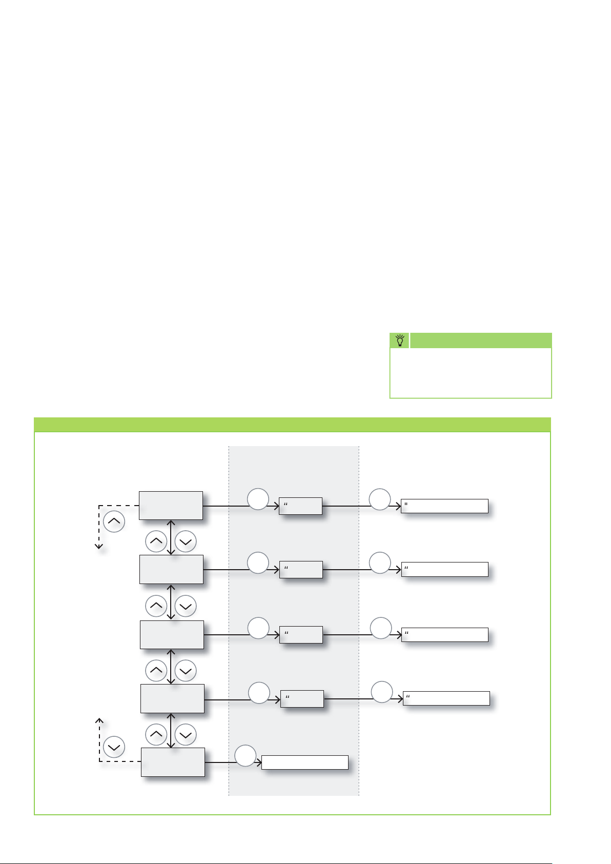
Menu structure
To define the setpoints using
theintegrated operator panel, hold
down the “OK” key for 5 seconds
so that the display switches from
the humidity currently measured
to the menu item rHXX.
If you would like to exit
the menu, do not press any
keys on the operator panel for
10 seconds.
Menu items
Code: RH
The code “RH” stands for
the relative air humidity that
the unit should reach. The value
can be set between 40 and
99 % RH. The default value is 60.
Code: °C
The code “°C” stands for external
heating control with the aim
of reaching a defined setpoint.
The value can be set to between
05 and 34. This value is set to
“OF” by default.
Code: EF
The code “EF” stands for external
heating control with the aim of
reaching the specified air humidity
more quickly. The set value may
differ from the setpoint humidity
so that the external heating can
either operate permanently or
merely provide a support function.
The value can be set between 40
and 99 % RH. The default value is
set to “OF” in this case.
Code: SI
The code “SI” stands for
themaintenance interval that
the operator or fitter requires.
Thisvalue is indicated in weeks
and can be set from 01 to 99.
Thedefault value is “OF.”
Code: tE
The code “tE” stands for testing
and the value “St” for self-test.
To start the self-test, press “OK”
and to cancel it, hold the down
key down for 5 seconds.
NOTE
The corresponding terminals
for these options are located on
the control board of the unit.
Menu structure of the SLN air dehumidifier
1. Level
rHXX
°CXX
External heating
EFXX
External fan
SIXX
Service interval
2. Level
OK
OK OK
OK
OK
“Value”
“Value”
“Value”
“Value”
OK
OK
OK
3. Level
"Value confirmed"
“Value confirmed"
“Value confirmed”
“Value confirmed”
14
tESt
Self-test
OK
“Test confirmed”

Unit function
Fan control
When the control board puts
the dehumidifier into operation,
the fan(s) switch on together
with the compressor.
Defrosting
The units feature an intelligent
and active defrosting function.
If the room temperature is below
20 °C, the evaporator will start to
ice up after a short time.
If the evaporator probe registers
a temperature of less than 5 °C
on the evaporator surface,
the unit only continues to
run in dehumidification mode for
a further 30 minutes.
Once this time has expired,
the fans stop and the solenoid
valve for hot-gas defrosting opens.
When the evaporator probe
registers a temperature higher
than 5 ºC again, the solenoid
valve closes and the unit resumes
dehumidification.
Compressor control
The compressor has a 6 minute
restart delay as a safety function.
The delay period must elapse
before it is possible to restart
the compressor.
This safety function protects
the compressor against an
overload caused by overly high
pressure in the cooling cycle.
In order to prevent damage
to the condenser, the units are
equipped with a mechanism
that prevents the compressor
being immediately switched back
on after it is switched off via
the mains power supply.
The compressor does not switch
back on until after a waiting time
of approx. 30 seconds!
Safety circuit
If the temperature exceeds 55 °C
on the condenser (e.g. due to a
fan failure or an overly high room
temperature (higher than 36 °C)),
the compressor stops automatically
to prevent an overload.
As soon as the temperature
on the condensor permits
dehumidification again, the unit
starts up automatically.
15

REMKO SLN Series
Wireless remote control
Wireless remote control
Wireless remote control allows
an SLN unit to be operated
and adjusted in a simple and
convenient manner. The current
humidity and temperature can be
viewed on the wireless remote
control and the setpoint humidity
can be adjusted.
The wireless remote control is
intended for use with the dehumidifier
models SLN 45-65-85.
The wireless remote control has
a coverage distance of up to
50 metres from the installation
location of the unit.
Overview of the display
Design of the wireless remote
control
The wireless remote control is
equipped with a large, clear display
and has operating buttons for
the different options Up, Down,
Left, Right and Enter.
The display values and the air
humidity scale have a value range
of 0 to 99 % RH.
The display values and the air
temperature scale have a value
range of 0 °C to 40 °C.
Information display
The information display shows
the setpoint values for the unit.
Fault messages together with
the fault symbols are also
displayed here.
Humidity indicator
and scale
External fan
Operating button control options
Dehumidification External heating
Fault symbol Information display
Up
Left
(Decrease value)
Remote control lock Battery indicator
Wireless symbol
Service Temperature indicator
and scale
Right
(Increase value)
Power supply
The wireless remote control can
be powered using 2 AAA batteries
with 1.5 V each or can be powered
externally using the USB cable
provided.
16
Down
Enter
(Change menu item)

Coupling
Connecting the antenna
The antenna is located on
the control board inside the unit
or can be fitted there. This will
be pre-installed if the unit
is delivered together with
the remote control.
Before fitting the antenna,
disconnect the unit from the power
supply. Then slacken the two
fastening screws on the underside
of the unit, tilt the front cover of
the unit and lift it up. In the upper
right area, remove the two screws
on the board cover and remove
the cover. Pull the control board
forwards, screw the antenna
into place and bend it forwards.
Once the antenna is screwed in
place and the board has been
returned to the previous position,
the unit can now be provided
with power in order to couple it
with the wireless remote control.
Then screw the housing parts back
into place.
Location of the control board
Connecting the antenna
Switching on and coupling
the remote control
The wireless remote control must
be coupled with the unit before
it can be used. To do so, carry out
the following steps.
1. Insert the batteries provided
into the battery compartment
on the rear of the wireless remote
control.
2a. The remote control will search
for the unit for two minutes.
During this time, the remote
control display flashes every
2 seconds.
2b. During the search phase,
hold down the Up and Down
keys on the operator panel of
the control board at the same time
for 5 seconds.
3. If coupling was successful,
the unit sends a serial number
to the wireless remote control
and the wireless symbol is
displayed.
4. The swimming pool
dehumidifier confirms
the connection by displaying
the code “Conn” for a period
of 3 seconds.
This procedure can also be carried
out using several remote controls
so that an air dehumidifier can
be controller by several remote
controls.
Coupling failure
If the wireless remote control
fails to couple with the unit,
the fault symbol becomes visible,
“Conn” is shown permanently
on the display and the wireless
symbol flashes.
The wireless remote control
needs to be reset before a new
coupling attempt can be made.
To do so, hold the Left key on
the wireless remote control down
for 10 seconds.
17

REMKO SLN Series
General
The wireless remote control
displays the values for humidity
and temperature at all times.
The values only disappear when
a malfunction arises.
Depending on which function
is currently active, one or more
of the symbols appear in the
centre of the display.
User setup menu
Hold down the Enter key for
3 seconds to open the user setup
menu.
In this menu it is possible to switch
between the wireless remote
control symbols using the Up and
Down keys provided the
corresponding option of “OF” has
been set to a value on the control
board itself. Please read pages
11 and 12 to set these values.
User setup menu symbols
External heating
Fitter setup menu
Hold down the Right key for
5 seconds to open the fitter setup
menu. At this point it is possible
to access all four menu items. It is
also necessary to set the respective
“OF” option on the control board
to a specific value to enable access.
Fitter setup menu symbols
External heating
Dehumidification
External fan
Maintenance interval
Fault messages
The fault messages correspond
to the alarm messages which can
also be shown on the unit’s control
board display. To make the alarm
message recognizable, the fault
symbol is also displayed on
the wireless remote control.
Fault priority
In the event that several faults
occur at the same time, only
the fault with the highest priority
is displayed.
Fault priority
HP High priority
LP
SEnS
Abt
AbrH Low priority
NOTE
Do not simply reset the fault
messages without establishing
the cause first.
Maintenance message
Unlike the other fault messages,
the maintenance message can
be acknowledged or reset via
the wireless remote control.
This is due to the fact that it is
a purely informative message.
Maintenance message
Dehumidification
The Left and Right keys can be
used to set these parameter values.
The parameter is confirmed as
a new setpoint using the Enter
key. When this is confirmed,
the remote control switches back
to the symbol and exits the menu.
If you would like to exit the user
setup menu, do not press any
keys on the remote control for
10 seconds.
18
Examples of fault messages
Sensor fault
Overly high
pressure level
detected
Generally speaking, the fault
messages can only be reset
on the display panel of the
control board. The unit must be
thoroughly inspected and the fault
reset following rectification each
and every time.
No changes can be made to
the setpoints in the setup menus
while there is an active fault.
Proceed as follows to set up
the new maintenance interval.
1. Hold down the Right key for
5 seconds to open the fitter menu.
2. Use the Up and Down keys
to navigate to the maintenance
symbol.
3. Use the Right and Left keys to
change the 0 value to the required
maintenance interval.
4. Confirm the new maintenance
interval by pressing the Enter key.

Care and maintenance
NOTE
Regular care and maintenance
is fundamental to a long
service life and fault-free
operation of the unit.
All moving parts have a lowmaintenance permanent coat
of lubricant. The refrigerant system
is designed as a hermetically sealed
system and may only be repaired
by a specialist.
■
Observe the regular care and
maintenance intervals
■
In accordance with
the operating conditions,
the units must be checked as
and when required, but at least
once per year, by a specialist
to ensure that they are in
a condition that is safe to use
■
Keep the units free of dust and
other debris
■
If the unit is contaminated,
it can be cleaned using
a vacuum cleaner. The
condensor in particular must
be vacuumed thoroughly
Cleaning the suction filter
Check the suction filter at regular
intervals and clean if necessary.
The filter is secured in a bracket
behind the intake openings.
CAUTION
Check the intake
openings, as well as filters,
regularly for contamination.
■
Light filter contamination can be
remedied with careful blowing
or suction
■
Heavier contamination may
be remedied by rinsing the filter
in a lukewarm (max. 40 °C)
soap solution Finally, always
rinse the filter carefully with
clear water and allow to dry
■
Before refitting the filter, ensure
that its fully dry and that no
damage has been sustained
■
The units may only be operated
with the filter in place
and
outlet
Operating LED
The multi-colour LED display
is located at the upper edge
in the centre of the unit. They
indicate the current operating
state of the unit.
Legend of the LED colours
The LED lights up “blue” and
stays that way when the unit is
connected to the mains power
supply.
The LED lights up “green”
and stays that way when
the compressor is in operation
and the unit is in dehumidifying
ordefrosting mode.
The LED lights up “yellow”
and stays that way when the unitis
operating in wireless remotecontrol
mode.
The LED lights up “red” when
a fault has occurred. Please refer
to the Troubleshooting chapter
torectify the fault.
■
If the evaporator’s fins are
heavily soiled, they can be
cleaned carefully with soapy
water
■
Never subject to direct jets
of water e.g. pressure washers
etc.
■
Never use abrasive or solvent-
based cleaners
■
Use only suitable cleaners, even
for heavy contamination
NOTE
Heavily contaminated filters
must be replaced with new
parts.
Only original replacement
parts may be used.
Cleaning the condensate
water collection tray
To ensure that the condensate
water that accumulates can always
drain freely, the collection tray for
the condensate and the drain must
be cleaned regularly.
19

REMKO SLN Series
Troubleshooting
Malfunction Possible cause Remedial measures
•Theunitdoesnotstart.
•Thedisplaydoesnotlightup.
•Theunitdoesnotstart.
•Displayindicatesincorrecttype.
•Thecompressordoesnotstart. The compressor switched off
No mains voltage. • Checkthepowersupplyorfuses
Air humidity in room too low.
The unit is outwith its usable
limits of 10 - 36 °C.
automatically due to an overly
high condensor temperature.
Lack of air ventilation.
Overly high ambient
temperature.
Contaminated filter/intake
device.
or switches on site.
• Checktheintegratedhygrostatand
set it to a low relative humidity,
e.g. < 40 % RH.
• Checktheroomconditionsand
alter as required.
Check the following points if the unit
does not start after 45 minutes:
• Checkifthefan(s)is/areworking.
• Checkiftheintakelteris
contaminated.
• Checkthattheintakeandoutlet
openings are free of contamination.
• Checkifthecondensorns
are contaminated.
• Checkiftheroomtemperature
is above 36 °C.
If the room temperature is above
36°C, the unit must be switched
off.
NOTE
If it is not possible to determine
the cause of the fault, switch
off the unit immediately and
disconnect it from the mains power
supply to prevent further damage.
NOTE
If all of the functional checks
have been carried out without
any findings, please contact
an authorised service station.
20
CAUTION
Work on the refrigerant
system and on the electrical
equipment must only be
conducted by a speciallyauthorised specialist!
CAUTION
Prior to maintenance
or repair work, the unit
must be disconnected from
the mains power supply.

Fault messages
Code and
value
LOSS
Abt
AbrH
SEnS Sensor fault, causes the unit to stop
The connection to the remote
control has been lost
Ambient temperature is outwith
the permissible range
Air humidity is outwith the
permissible range
Cause Remedial measures
When the connection is restored, acknowledge
by clicking “OK”.
Acknowledgement not possible. Automatic reset as soon
as the temperature has returned to the permissible range.
Acknowledgement not possible. Automatic reset as soon
as the air humidity has returned to the permissible range.
Press the Up or Down key to see which probe is affected.
Exchange the probe if necessary.
COnd - condensor probe
EUAP - evaporator probe
RH°t - humidity and temperature probe
Acknowledgement possible only by way of unlocking
sequence. Initiate the sequence by pressing the “OK”
key.
Malfunction must be established and rectified
LP Low pressure level detected
HP High pressure level detected
Unlocking sequence
Once the unlocking sequence has been initiated, the unit displays the information “Loc”. If the Down key
is pressed at this point, the information display switches to “UnLo” which displays the unlocking option.
If “UnLo” is confirmed with the “OK” key, the unit is enabled again.
by specialist personnel. Acknowledgement possible
only by way of unlocking sequence. Initiate the sequence
by pressing the “OK” key.
Malfunction must be established and rectified
by specialist personnel. Acknowledgement possible
only by way of unlocking sequence. Initiate the sequence
by pressing the “OK” key.
Information messages
Code and
value
Log
After inserting a USB memory stick
into the USB interface
Occurrence Comment
Once the USB stick has been inserted, the process
of copying the log data from the internal memory
to the USB memory stick is initiated and declared
as finished by the information “Log”.
21

REMKO SLN Series
Cooling cycle
7
1
3
SLN 45 - 85
5
6
2
4
Legend:
1. Compressor
2. Evaporator
3. Condenser
4. Thermal expansion valve
5. Dry filter
6. Solenoid valve
7. Fan
22
We reserve the right to modify the dimensions and design as part of the ongoing technical development process.

Electrical wiring diagram
SLN 45 - 85
Electronic control board
Remote
Display
Legend:
FAN 1 = fan motor 1
FAN 2 = fan motor 2
FAN 3 = fan motor 3
CAP 1 = capacitor 1
CAP 2 = capacitor 2
CAP 3 = capacitor 3
L
N
PE
USB
RS485
_
Ext. RH/T
COMP. = compressor
VALVE = solenoid valve
RUN = potential-free contact
FAIL = potential-free contact
HEAT 1/2 = 12 V supply voltage
for controlling relays
NOTE
Alarm
12 V DC
Operator panel
Bedienfeld
Fan motors:
SLN 45 = FAN 1
SLN 65 = FAN 1 and FAN 2
SLN 85 = FAN 1, FAN 2 and
FAN 3
CAUTION
A main switch should be installed
NOTE
at a suitable and easily accessible
Prior to maintenance
or assembly work, the unit
must be disconnected from
the mains power supply.
We reserve the right to modify the dimensions and design as part of the ongoing technical development process.
point in the mains supply line.
We recommend using a mains
supply line of 2.5 mm² for
the units.
Assembly and maintenance
work on the units may only
be carried out by authorised
and qualified technicians.
23

REMKO SLN Series
Intended use
The units are designed exclusively
for dehumidification purposes
on the basis of their structural
design and equipment.
A failure to observe
the manufacturer's specifications,
the respective local legal
requirements or arbitrary
alterations to the units, exempts
the manufacturer from liability
for resulting damage.
NOTE
Operation other than the types
listed in this operating manual
is prohibited.
With non-observance,
any manufacturer liability
or guarantee claims are voided.
Customer service and
guarantee
As a prerequisite for any guarantee
claims to be considered, it is
essential that the ordering party
or their representative complete
and return the “Certificate of
guarantee” to REMKO GmbH &
Co. KG at the time when the units
are purchased and commissioned.
The units are tested several times
to verify their correct function.
However, if malfunctions should
arise that cannot be remedied by
the operator with the assistance of
the troubleshooting section, please
contact your specialist dealer or
contractual partner.
Environmental protection and recycling
Disposal of packaging
When disposing of packaging
material, please consider our
environment.
Our units are carefully packed
and delivered in stable transport
packaging and, if applicable, on
a wooden pallet.
The packaging materials are
environmentally-friendly and can
be recycled.
By recycling packaging materials,
you make a valuable contribution
to the reduction of waste and
conservation of raw materials.
Therefore, only dispose of
packaging material at appropriate
collection points.
CAUTION
Copyright
The redistribution, even
in part, or the use of
this documentation for
purposes other than intended
is strictly prohibited without
the written authorisation of
REMKO GmbH & Co. KG
.
NOTE
Setting and maintenance work
may only be carried out by
authorised and qualified
technicians.
Important information
concerning recycling
The units are operated with
environmentally-friendly and
ozone-neutral R407C refrigerant.
The mixture of refrigerant and oil
within the unit must be disposed
of properly in accordance with
the statutory or locally-applicable
regulations.
Disposal of the old unit
The manufacturing process for
the units is subject to continuous
quality control.
Only high-grade materials are
processed, the majority of which
are recyclable.
You also contribute to
environmental protection by
ensuring that your old equipment
is only disposed of in an
environment friendly manner.
Therefore, only bring the old
unit to an authorised recycling
business or to an appropriate
collection point
.
24

Exploded view of the unit
2
3
4
1
8
22
21
5
6
7
9
10
11
12
13
14
15
20
19
18
17
16
25

REMKO SLN Series
Spare parts list
No. Designation SLN 45 SLN 65 SLN 85
1 Wall-mounted bracket
2 Wall spacer
3 Cable gland
4 Series terminals on DIN rail
5 Control board
6 Holder for control board with operator panel
7 Condenser fan
8 Compressor capacitor
9 Spatter guard
10 Compressor
11 Compressor accessories
12 Solenoid valve
13 Dry filter
14 Copper piping set
15 Condensate tray
16 Housing cover
17 Fan module
18 Fan
19 Evaporator
20 Condenser
21 Temperature valve
22 Compressor insulation.
- Air circulation intake filter (duct)
EDP no. on request
26
When ordering replacement parts, please always state the EDP no. and unit number (see name plate)!

RS-485 interface
The RS-485 interface uses the Modbus RTU protocol as a slave unit. The unit does not have an address.
Settings: 115200, N, 8, 1. It accepts queries for any address.
Code functions
0x06 Present single register
0x10 Present multiple register
0x03 Read holding register
Register Byte
2 Comp_state 0 1 0
2
3 Fan_state 0 1 0
4 Sole_state 0 1 0
3
5 ExFan_state 0 1 0
6 Heat1_state 0 1 0
4
7 Heat2_state 0 1 0
8 Alarm1_state 0 1 0
5
9 Alarm2_state 0 1 0
10
6
11
Database
parameters
Evap_temp1
(decimal)
Evap_temp1
(fraction)
Min Max Hr. Description
Compressor status:
0 – Compressor stopped 1 – Compressor running
Fan status:
0 – Fan stopped 1 – Fan running
Solenoid valve:
0 – closed
1 – open
Extractor fan status:
0 – Fan stopped
1 – Fan running
Status HEAT 1:
0 – HEAT 1 off
1 – HEAT 1 on
Status HEAT 2:
0 – HEAT 2 off
1 – HEAT 2 on
Output alarm 1:
0 – Alarm output off
1 – Alarm output on
Output alarm 2:
0 – Alarm output off
1 – Alarm output on
-40 100 0
-40 100 0
Temperature of evaporator 1:
Decimal: Can be used as an integer value for
temperature.
Fraction: Can be converted to a decimal value.
To obtain the total value, use the equation for
floating-point numbers: “Value = decimal +
(fraction/256)”.
12
7
13
Evap_temp2
(decimal)
Evap_temp2
(fraction)
-40 100 0
-40 100 0
Temperature of evaporator 2:
Use as described above.
27

REMKO SLN Series
Register Byte
14
8
15
16
9
17
18
10
19
20
11
21
Database
parameters
Cond_temp1
(decimal)
Cond_temp1
(fraction)
Aux_temp
(fraction)
Aux_temp
(fraction)
Amb_temp
(decimal)
Amb_temp
(fraction)
Amb_hum
(high byte)
Amb_hum
(low byte)
Min Max Hr. Description
-40 100 0
-40 100 0
-40 100 0
-40 100 0
-40 100 0
-40 100 0
0 100 0
Condenser temperature:
Use as described above.
Auxiliary probe temperature:
Use as described above.
Ambient air temperature:
Use as described above.
Ambient air humidity:
High byte is insignificant and always contains
zero. Only low byte can be used.
12
13
16
17
18
19
22 RH_set 40 95 40 Humidity setpoint.
23 RH_Fan 40 95 40 Humidity setpoint for extractor fan start.
24
25
30 Fail_start 0 1 0 Status of Fail_start mode.
31 SB_mode 0 1 0 Standby mode status.
32 DEH_mode 0 1 0 Dehumidification status.
33 Ice_mode 0 1 0 Defrosting mode.
34 LP_mode 0 1 0 LP fault mode status.
35 Sens_mode 0 1 0 Sensor fault mode status.
36 HP_mode 0
37 Amb_mode 0 1 0 Ambient fault mode status.
Temp_set
(decimal)
Temp_set
(fraction)
0 36 0
1 0 HP fault mode status.
Temperature setpoint:
Used in the same way as Evap_temp1.
28
20
38
39
AmbT_
mode
AmbRH_
mode
0 1 0 Ambient temperature fault mode status.
0 1 0 Ambient humidity fault mode status.

Register Byte
Database
parameters
Min Max Hr. Description
21
22
23
41
42
40
41
42
43
44
45
number (high)
number (low)
Software version
(main version)
Software version
(minor version)
HP alarm temp.
HP alarm temp.
80
Fan_function 0 1 0 Activate fan function in standby mode.
81
82
Time_wait_fan 60 7200 3600
83
SW build
SW build
(decimal)
(fraction)
0
65535 x Software build number.
0
0 255 x Main version number of the software.
0 255 x Minor version number of the software.
HP faults occur when Cond_temp1 is greater than
0 99 60
this value.
Used in the same way as Evap_temp1.
Waiting time until fan starts up in standby mode,
if activated (seconds).
43
44
45
84
Time_run_fan 15 600 60
85
Fan operating time in standby mode, if activated
(seconds).
86 RH_Fen 0 1 0 Activate/deactivate extractor fan function.
87 Service_ena 0 1 0 Activate/deactivate maintenance interval function.
88
Service_int 0 99 0 Maintenance interval value in weeks.
89
29

REMKO SLN Series
USB interface
The USB interface is used for transferring data logs from the unit to a USB stick.
The unit data is saved every three hours and stored in the internal memory. Switching the status to fault mode
also triggers the storage of data.
If the memory is completely full, the oldest logs are overwritten by the newest logs.
When a USB stick is inserted into the USB interface, all of the logs that have been recorded are saved in the CSV
file “data_log.csv”. The data is the internal memory is not deleted as a result of this process and can therefore
be transferred to several USB sticks.
The data log is saved in the form of the following parameters:
Database parameters Size (bits) Output text CSV column
Work_time 32 <dd:mm:hh:ss> Time stamp
Amb_temp 8 <Value> T_amb
Amb_int_temp 8 <Value> T_amb_int
Amb_ext_temp 8 <Value> T_amb_ext
Aux_temp 8 <Value> T_aux
Cond_temp1 8 <Value> T_cond
Evap_temp1 8 <Value> T_evap1
Evap_temp2 8 <Value> T_evap2
Temp_set 8 <Value> T_set
Amb_hum 8 <Value> RH_amb
Amb_int_hum 8 <Value> RH_amb_int
Amb_ext_hum 8 <Value> RH_amb_ext
RH_set 8 <Value> RH_set
RH_Fan 8 <Value> ExtFanSet
Evap_temp_err 1 EVAP Error
Cond_temp_err 1 COND Error
Aux_temp_err 1 AUX Error
Amb_int_err 1 AMB_INT Error
Amb_ext_err 1 AMB_EXT Error
SB_mode 1 SB Mode
Startup_mode 1 STARTUP Mode
DEH_mode 1 DEH Mode
Ice_mode 1 ICE Mode
LP_mode 1 LP Mode
HP_mode 1 HP Mode
Sens_mode 1 SENS Mode
AmbT_mode 1 AMBT Mode
AmbRH_mode 1 AMBRH Mode
Service_ena 1 ENABLED Mode
30

Maintenance protocol
Unit type: .................................. Unit number: ...................................
1 2 3 4 5 6 7 8 9 10 11 12 13 14 15 16 17 18 19 20
Unit cleaned - outside -
Unit cleaned - inside -
Condenser cleaned
Evaporator cleaned
Fan function checked
Unit checked for damage
Safety devices checked
All fastening screws checked
Electrical safety check
Test run
Comments: ..........................................................................................................................................................
✍
.............................................................................................................................................................................
.............................................................................................................................................................................
.............................................................................................................................................................................
1. Date: ..............
..............................
Signature
6. Date: ..............
..............................
Signature
11. Date: ............
..............................
Signature
16. Date: ............
..............................
Signature
2. Date: ..............
..............................
Signature
7. Date: ..............
..............................
Signature
12. Date: ............
..............................
Signature
17. Date: ............
..............................
Signature
3. Date: ..............
..............................
Signature
8. Date: ..............
..............................
Signature
13. Date: ............
..............................
Signature
18. Date: ............
..............................
Signature
4. Date: ..............
..............................
Signature
9. Date: ..............
..............................
Signature
14. Date: ............
..............................
Signature
19. Date: ............
..............................
Signature
5. Date: ..............
..............................
Signature
10. Date: ............
..............................
Signature
15. Date: ............
..............................
Signature
20. Date: ............
..............................
Signature
Unit to be maintained only by authorised specialists in accordance with the statutory regulations.
31

REMKO SLN Series
Technical data
Series SLN 45 SLN 65 SLN 85
Daily dehumidification capacity at 30 °C and 80 % RH Litres/day 47 78 104
Daily dehumidification capacity at 30 °C and 60% RH Litres/day 35.5 56.2 78.8
Operational temperature range °C 10 to 36
Usable humidity range
Air volume m
% RH 40 to 100
3
/h 400 680 900
Power supply V/Hz 230/1~/50
Max. power consumption kW 0.9 1.5 1.8
Max. rated current consumption A 3.8 6.6 8
Max. switching voltage from RUN and FAIL contact V 50 50 50
Max. switching current from RUN and FAIL contact A 0.5 0.5 0.5
HEAT contact voltage V 12 12 12
Maximum current limit of a HEAT contact mA 60 60 60
Refrigerant
1)
R407C
Refrigerant quantity kg 0.7 0.9 1.2
Sound pressure level L
pA
1m
Depth / Width / Height mm
dB (A) 43 44 47
294/998/700 294/1148/700 294/1483/700
2)
Weight kg 57 66 77
IP enclosure class X4 X4 X4
EDP no. 616455 616655 616855
1) Contains greenhouse gas according to Kyoto protocol 2) Noise level measurement DIN 45635 - 13 - KL 3 carried out at duct openings
Capacity diagram SLN 45
40
35
30
25
20
Room temperature [°C]
15
B
A
10
5
0
0 0,5 1 1,5 2 2,5
32
C
Dehumidification capacity [l/h]
40% r.F.
A
60% r.F.
B
80% r.F.
C

Capacity diagram SLN 65
40
35
40% r.F.
A
60% r.F.
B
30
25
20
Room temperature [°C]
15
B
A
10
5
0
0 0,5 1 1,5 2 2,5 3 3,5 4
C
Dehumidification capacity [l/h]
80% r.F.
C
Capacity diagram SLN 85
40
35
30
25
Room temperature [°C]
20
15
B
A
10
5
0
0 1 2 3 4 5
C
Dehumidification capacity [l/h]
40% r.F.
A
60% r.F.
B
80% r.F.
C

Notes


REMKO INTERNATIONAL
... and also right in your neighbourhood!
Take advantage of our experience and advice
REMKO GmbH & Co. KG
Air conditioning and heating technology
Im Seelenkamp 12 D-32791 Lage
Telephone +49 5232 606-0
Fax +49 5232 606-260
E-mail info@remko.de
Internet www.remko.de
Consulting
Thanks to intensive training,
our consultants are always
completely up-to-date when
it comes to technical expertise.
This has given us the reputation
of being more than just
an excellent, reliable supplier:
REMKO, a partner who helps
to solve problems.
Sales
REMKO offers not just a well
established sales network both
nationally and internationally, but
also has exceptionally highly-
qualified sales specialists.
REMKO employees in the field
are more than just sales
people: above all, they must
be advisers to our customers
in air conditioning and heating
technology.
Customer service
Our units operate precisely and
reliably. However, in the event
of a malfunction REMKO
customer service is quickly
on the scene. Our extensive
network of experienced dealers
guarantees quick and reliable
service.
We reserve the right to make technical changes and provide no warranty as to the accuracy of this data!
 Loading...