

Page 1

Assembly instructions
REMKO Safety assembly
0083-2014-05 Edition 1, en_GB
Read the instructions prior to performing any task!
Page 2

Made by REMKO
Read these operating instructions carefully before commissioning / using this device!
These instructions are an integral part of the system and must
always be kept near or on the device.
Subject to modifications; No liability accepted for errors or misprints!
Translation of the original assembly instructions
Page 3

Table of contents
1 Safety and usage instructions............................................................................................................. 4
1.1 General safety notes....................................................................................................................... 4
1.2 Identification of notes...................................................................................................................... 4
1.3 Personnel qualifications.................................................................................................................. 4
1.4 Dangers of failure to observe the safety notes................................................................................ 4
1.5 Safety-conscious working............................................................................................................... 4
1.6 Safety instructions for the operator................................................................................................. 5
1.7 Safety notes for installation and inspection tasks........................................................................... 5
1.8 Unauthorised modification and changes......................................................................................... 5
1.9 Intended use................................................................................................................................... 6
1.10 Safety-conscious working............................................................................................................. 4
1.11 Warranty........................................................................................................................................ 6
1.12 Transportation and packaging....................................................................................................... 6
1.13 Environmental protection and recycling........................................................................................ 6
2 Technical data....................................................................................................................................... 7
2.1 Technical data for the safety valve.................................................................................................. 7
2.2 Dimensions of the safety assembly................................................................................................. 7
3 Description of the safety assembly..................................................................................................... 8
4
Installation............................................................................................................................................. 8
5 Commissioning..................................................................................................................................... 9
6 Index..................................................................................................................................................... 10
3
Page 4
REMKO Safety assembly
1
1.1
Carefully read the operating manual before commissioning the units for the first time. It contains
useful tips and notes such as hazard warnings to
prevent personal injury and material damage.
Failure to follow the directions in this manual not
only presents a danger to people, the environment
and the system itself, but will void any claims for
liability.
Keep this operating manual and the refrigerant
data sheet near to the units.
1.2
This section provides an overview of all important
safety aspects for proper protection of people and
safe and fault-free operation.The instructions and
safety notes contained within this manual must be
observed in order to prevent accidents, personal
injury and material damage.
Notes attached directly to the units must be
observed in their entirety and be kept in a fully
legible condition.
Safety notes in this manual are indicated by symbols. Safety notes are introduced with signal words
which help to highlight the magnitude of the danger
in question.
Safety and usage instructions
General safety notes
Identification of notes
DANGER!
CAUTION!
This combination of symbol and signal word
warns of a potentially hazardous situation,
which if not avoided may cause injury or material and environmental damage.
NOTICE!
This combination of symbol and signal word
warns of a potentially hazardous situation,
which if not avoided may cause material and
environmental damage.
This symbol highlights useful tips and recommendations as well as information for efficient
and fault-free operation.
1.3
Personnel qualifications
Personnel responsible for commissioning, operation, maintenance, inspection and installation must
be able to demonstrate that they hold a qualification which proves their ability to undertake the
work.
Contact with live parts poses an immediate
danger of death due to electric shock. Damage
to the insulation or individual components may
pose a danger of death.
DANGER!
This combination of symbol and signal word
warns of a situation in which there is immediate
danger, which if not avoided may be fatal or
cause serious injury.
WARNING!
This combination of symbol and signal word
warns of a potentially hazardous situation,
which if not avoided may be fatal or cause
serious injury.
Dangers of failure to observe
1.4
the safety notes
Failure to observe the safety notes may pose a risk
to people, the environment and the units. Failure to
observe the safety notes may void any claims for
damages.
In particular, failure to observe the safety notes
may pose the following risks:
n The failure of important unit functions.
n The failure of prescribed methods of mainte-
nance and repair.
n Danger to people on account of electrical and
mechanical effects.
1.5
Safety-conscious working
The safety notes contained in this installation and
operating manual, the existing national regulations
concerning accident prevention as well as any
internal company working, operating and safety
regulations must be observed.
4
Page 5

Safety instructions for the oper-
1.6
ator
The operational safety of the units and components is only assured providing they are used as
intended and in a fully assembled state.
n The units and components may only be set up,
installed and maintained by qualified personnel.
n The existing regulations concerning accident
prevention must be adhered to.
n Do not operate units or components with
obvious defects or signs of damage.
n Contact with equipment parts or components
can lead to burns or injury.
n Ensure that electrical energy does not pose a
risk.
n Regulations of the VDE and the local energy
supply company must be adhered to.
NOTICE!
Material damage due to mineral oils!
Mineral oil products permanently damage
EPDM seal elements; the sealing properties
may therefore be lost. We do not take responsibility or provide warranty replacements for
damage caused by seals that are damaged in
this way.
– It is essential that you prevent EPDM from
coming into contact with mineral oil substances.
– Use a lubricant that is free of mineral oil
and has a silicone or polyalkylene basis,
such as Unisilkon L250L and Syntheso
Glep 1 made by Klüber, or a silicon spray.
Safety notes for installation and
1.7
inspection tasks
n The operator must ensure that all inspection
and installation work is carried out by authorised and qualified personnel who have thoroughly read the operating manual.
n Works on the pump/system may only be car-
ried out whilst at a standstill as a matter of principle.
n Appropriate hazard prevention measures must
be taken to prevent risks to people when performing installation, repair, maintenance or
cleaning work on the units.
n The setup, connection and operation of the
units and its components must be undertaken
in accordance with the usage and operating
conditions stipulated in this manual and comply
with all applicable regional regulations.
n Regional regulations and laws as well as the
Water Ecology Act must be observed.
n The power supply should be adapted to the
requirements of the units.
n The units and components must be kept at an
adequate distance from flammable, explosive,
combustible, abrasive and dirty areas or
atmospheres.
n Safety devices may not be modified or
bypassed.
NOTICE!
Malfunction!
The fresh water module must be integrated into
the equipotential bonding system of the electrical installation. If this is not ensured by the
pipe network, set up an approved potential
equalisation connection to the main potential
connection.
Unauthorised modification and
1.8
changes
The operational safety of the fresh water module
that was delivered is guaranteed only with
intended use in accordance with section 1.8 of the
operating instructions. Under no circumstances
should the threshold values specified in the datasheet be exceeded.
Modifications or changes to units and components
are not permitted and may cause malfunctions.
Safety devices may not be modified or bypassed.
Original replacement parts and accessories
authorised by the manufacturer ensure safety. The
use of other parts may invalidate liability for
resulting consequences.
5
Page 6

REMKO Safety assembly
1.9
Intended use
The safety assembly must only be used for closed
heating systems per EN 12828 for power ratings
up to 50 kW.
Any different or additional use is a non-intended
use. The manufacturer/supplier assumes no liability for damages arising from a non-intended use.
The user bears the sole risk in such cases.
Intended use also includes working in accordance
with the operating and installation instructions and
complying with the maintenance requirements.
The threshold values specified in the technical
data must not be exceeded.
1.10
The safety notes contained in this installation and
operating manual, the existing national regulations
concerning accident prevention as well as any
internal company working, operating and safety
regulations must be observed.
1.11
For warranty claims to be considered, it is essential
that the ordering party or its representative complete and return the "certificate of warranty" to
REMKO GmbH & Co. KG at the time when the
units are purchased and commissioned.
The warranty conditions are detailed in the "General business and delivery conditions". Furthermore, only the parties to a contract can conclude
special agreements beyond these conditions. In
this case, contact your contractual partner in the
first instance.
Safety-conscious working
Warranty
WARNING!
Plastic films and bags etc. are dangerous
toys for children!
Why:
- Leave packaging material are not around.
- Packaging material may not be accessible to
children!
1.13
Disposing of packaging
All products are packed for transport in environmentally friendly materials. Make a valuable contribution to reducing waste and sustaining raw materials. Only dispose of packaging at approved
collection points.
Disposing of the units and their components
For the manufacture of the units and components,
only recyclable materials have been used. Help
protect the environment by ensuring that the units
or components (for example batteries) are not disposed of in household waste, but only in accordance with local regulations and in an environmentally safe manner, e.g. using authorised disposal
and recycling specialists or council collection
points.
Environmental protection and recycling
1.12
The units are shipped in sturdy transport packaging or within the heat pump housing. Immediately check the units on delivery and make a note
of any damage or missing parts on the delivery
note. Inform the forwarding agent and contractual
partner. Claims under guarantee made at a later
date will not be accepted.
Transportation and packaging
6
Page 7
2
1
2
2
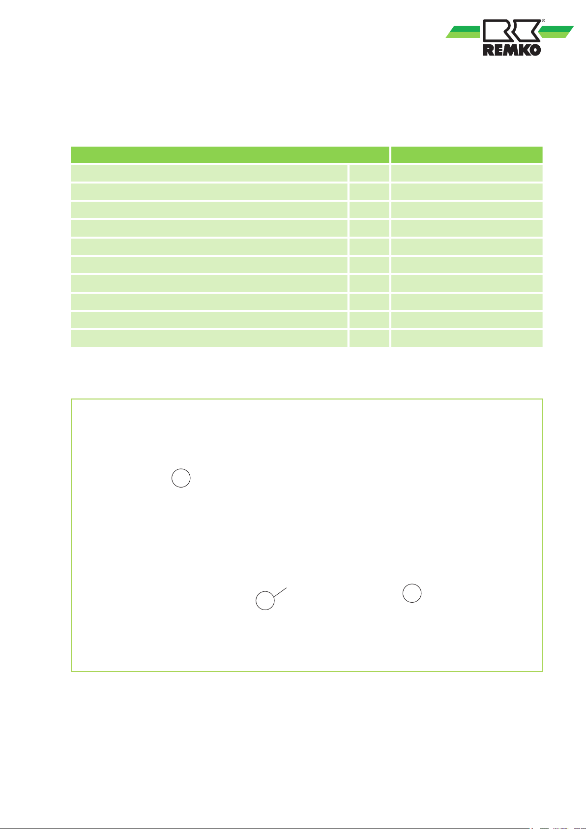
2.1
Diaphragm safety valve
Body DIN EN 12165 CW 617N
Handle ABS
Seal EPDM
Nominal pressure PN10
Perm. max. operating temperature °C 120
Operating liquid Glycol-water mix, max 50%
Categorisation per pressurised equipment directive PED IV
Inlet connection / outlet connection Inches 1/2" x 3/4"
Trigger pressure bar 2.5 - 3.0
EDP no. 11200010
2.2
Technical data
Technical data for the safety valve
Dimensions of the safety assembly
Fig. 1: Dimensions of the safety assembly
1: Internal thread 1"
2: Polystyrene shell as insulation (per DIN 4102-A1)
7
Page 8
REMKO Safety assembly
3
Diaphragm safety valve
The diaphragm safety valves were manufactured
in accordance with the safety requirements of the
pressure equipment directive 97/23/EC and are
TÜV-certified (with enlarged outlet, type-tested per
TRD 721 VdTÜV bulletin for safety valve SV100).
Safety assembly
The manifold is made from solid cast brass
CB753S. The small air bubbles in heating water
are automatically routed to the fast-bleeder, thanks
to the special design.
The lower connection, for the heat pump connection line, has a 1" internal thread.
A pre-formed polystyrene shell per DIN 4102-A1
provides insulation.
The complete safety assembly comprises:
1. A heating manometer 1/4", ø 63 mm, with
2. An automatic fast-bleeder with a shut-off
3. A diaphragm safety valve 1/2" x 3/4", type-
The safety assembly can only be used for closed
heating systems per EN 12828 for power ratings
up to 50 KW.
Description of the safety assembly
NOTICE!
In order to avoid damage, the installation, commissioning and maintenance of the diaphragm
safety valves must always be implemented as
stipulated in the installation instructions.
green flag and red position indicator and
metal housing. The automatic shut-off valve
3/8" x 1/4" enables trouble-free replacement
without having to empty the system.
valve, brass design, a float made from high
quality plastic and functionally reliable valve.
Connection = 3/8" with an O-ring seal.
tested, in compact brass design and a trigger
pressure of 3 bar for power ratings up to 50
kW or 45 000 kcal/h.
4
The fittings and equipment (manometer, quickbleeder and safety valve) are sealed into the manifold and checked for functionality and leak-tightness. Install the safety valve per EN 12828, above
the level and in the immediate vicinity of the heat
generator.
Route the connecting line (min. 3/4" DN = 20 mm)
with standard permissible materials keeping the
route as short as possible. No shut-off valve may
be installed.
Install the safety assembly such that the fittings are
all vertical.
The diameter of the discharge line for the safety
valve must comply with the diameter of the valve
outlet.
The max. length must not exceed 2m, more than 2
bends is not permitted. If these max. values are
exceeded (2 bends and 2 m line), then the next
largest dimension should be selected for the discharge line. Note that in this case, more than 3
bends and 4 m line length is also not permitted.
If the discharge line is routed in a drain line with a
funnel, the dimension of this drain line must have
twice the cross-section of the valve inlet. Furthermore, ensure that the discharge line is routed with
an incline. The mouth must be open and must be
observable and designed such that personnel are
not endangered by the discharge procedure
Installation
WARNING!
Water temperatures or water mix temperatures
over 50 °C can result in burns.
Ensure that these high temperatures do not
present any hazard to personnel during the
installation of the safety valve.
CAUTION!
Do not damage the connection threads during
installation. This will prevent damage to property and injury to personnel.
CAUTION!
All connections must be leak-tight.
8
Page 9
NOTICE!
A
B
GD E F
C
H
I
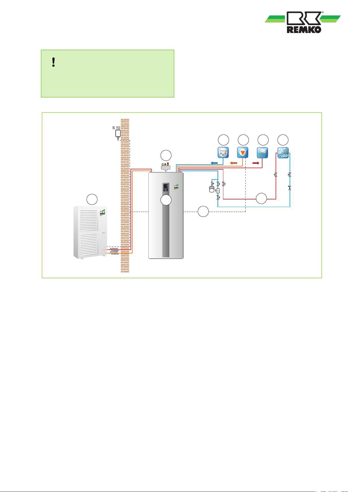
Carry out the installation such that the safety
assembly is located above the level of the heat
generator.
Fig. 2: Installation schematic
A: Outdoor unit
B: WKF series indoor unit
C: Safety assembly
D: Cold water
E: Circulation
5
With the initial commissioning of the heating
system, the heat pump is filled until the static pressure of the system is reached. The heat pump is
now brought to the max. heating temperature
whereby care should be taken to ensure that the
pressure increase does not exceed 2 bar. If this
does however exceed 2 bar then the expansion
vessel has been incorrectly selected.
The trigger pressure and rating of the diaphragm
safety valve can be found on the safety placard on
the red hand knob.
Commissioning
F: Hot water
G: Floor heating cycle
H: Supply line
I: Return line
9
Page 10

REMKO Safety assembly
6
C
Commissioning.................................................... 9
D
Description
Dimensions.......................................................... 7
Discharge line for the safety valve
E
Environmental protection..................................... 6
I
Installation............................................................ 8
Installation schematic........................................... 9
Intended use........................................................ 6
P
Packaging, disposal............................................. 6
R
Recycling............................................................. 6
Index
Boiler group
Diaphragm safety valve.................................. 8
Safety assembly.............................................. 8
Diameter......................................................... 8
Max. length..................................................... 8
Max. number of bends.................................... 8
..................................................... 8
S
Safety
Dangers of failure to observe the safety
notes............................................................... 4
General........................................................... 4
Identification of notes...................................... 4
Instructions for the operator............................ 5
Note for inspection work................................. 5
Note for installation work................................. 5
Personnel qualifications.................................. 4
Safety-conscious working........................... 4, 6
Unauthorised modification ............................. 5
Unauthorised replacement part manufacture.. 5
T
Technical data...................................................... 7
U
Unit disposal........................................................ 6
W
Warranty.............................................................. 6
10
Page 11

Page 12

Consulting
Thanks to intensive training,
our consultants are always
completely up-to-date in terms
of technical knowledge. This has
given us the reputation of being
more than just an excellent,
reliable supplier:
REMKO, a partner
helping you find solutions to
your problems.
Distribution
REMKO offers not just a well
established sales network both
nationally and internationally, but
also has exceptionally highlyqualified sales specialists.
REMKO field staff are more than
just sales representatives: above
all, they must act as advisers to
our customers in air conditioning
and heating technology.
SFlbCustomer Service
Our equipment operates
precisely and reliably. However,
in the event of a fault, REMKO
customer service is quickly at
the scene. Our comprehensive
network of experienced dealers
always guarantees quick and
reliable service.
REMKO INTERNATIONAL
… and also right in your neighbourhood!
Make use of our experience and advice
We reserve the right to make technical changes, and provide no guarantee as to the accuracy of this data!
REMKO GmbH & Co. KG
Air conditioning and heating technology
Im Seelenkamp 12 D-32791 Lage
Postfach 1827 D-32777 Lage
Telephone +49 5232 606-0
Telefax +49 52 32 606-2 60
E-mail [email protected]
Website www.remko.de
 Loading...