


REMKO ATY
ATY 261 DC, ATY 351 DC
Inverter wall - room air conditioner in split - design
Operation · Technology · Spare parts
Edition GB – V08


Contents
Safety notes
Environmental protection and recycling
Warranty
Transport and packaging
Equipment description
Operation
Shutdown
Care and maintenance
Troubleshooting and customer service
Control and resistance
Installation instructions for qualified personnel
Installation
Monitoring for leaks
4
4
4
5
5
6-14
15
15-16
17-18
19
20-23
23-25
25
Condensate drain
Electrical connection
Electrical connection diagram
Electrical circuit diagram
Before commissioning
Add refrigerant
Commissioning
Unit dimensions
Technical data
Exploded view
Spare parts list
Declaration of conformity
Read these operating instructions carefully before
commissioning / using the device!
26
26-27
27
28
28
28
29
30
31
32-33
32-33
34
Made by REMKO
These instructions are an integral part of the system and must always
be kept near or on the device .
Subject to modifications; No liability accepted for errors or misprints!
3

REMKO ATY
Safety notes
Carefully read this manual before
putting commissioning the
equipment. It provides useful
tips and information as well
as hazard warnings to prevent
injury or material damage .
Failure to follow the directions
in this manual can result in
endangerment to persons, the
environment and the equipment
itself and will void any claims for
liability.
■
Keep this manual and the
refrigerant datasheet near the
unit.
■ The unit may only be set up and
installed by qualified personnel.
■ The setup, connection and
operation of the unit and
its components must be in
accordance with the operating
conditions stipulated in this
manual and comply with all
applicable local regulations.
■ Mobile units must be set up
securely on suitable surfaces
and in an upright position.
Stationary units must be
permanently installed for
operation.
■ Modification of equipment
and components supplied by
REMKO is not permitted and
can cause malfunctions.
■ Equipment and components
may not be operated in areas
where there is an increased
risk of damage. Observe the
minimum clearances.
■ The electrical voltage supply
is to be adapted to the
requirements of the equipment.
■ The operational safety
of equipment and components
is only assured if they are used
as intended and fully assembled.
Safety devices may not be
modified or bypassed.
■ Do not operate equipment
or components with obvious
defects or signs of damage.
■ All housing parts and openings,
e.g. air inlets and outlets, must
be free of foreign objects, fluids
or gases.
■ The equipment and components
must be kept an adequate
distance from flammable,
explosive, combustible,
aggressive and dirty areas
or atmospheres.
■ Touching equipment parts can
result in burns or injury.
■ Installation, repair and
maintenance work may only
be carried out by authorised
specialists. Visual inspections
and cleaning can be performed
by the operator as long as the
equipment is not under voltage.
■ Take appropriate hazard
prevention measures when
performing installation, repair
or maintenance work or
cleaning the equipment.
■ The equipment or components
are not to be exposed to any
mechanical stresses, extreme
levels of humidity or direct
sunlight.
Environmental
protection and
recycling
Disposal of packaging
All products are packed for
transport in environmentally
friendly materials. Make a valuable
contribution to reducing waste
and sustaining raw materials. Only
dispose of packaging at approved
collection points.
Disposal of equipment
and components
Only recyclable materials are used
in the manufacture of the devices
and components,
Help protect the environment
by ensuring that the devices
or components (for example
batteries) are not disposed
in household waste, but
only in accordance with
local regulations and in
an environmentally safe manner,
e.g. using certified firms and
recycling specialists or at collection
points.
Warranty
In order to make warranty claims,
it s essential that the ordering
party or their representative
complete and return the "certificate
of warranty" and "commissioning
report" to REMKO GmbH &
Co. KG at the time when the
equipment was purchased and
commissioned. The warranty
conditions are detailed in the
"General terms and conditions".
Only the contractual parties can
strike special agreements beyond
these conditions. In this case, first
contact the contractual partner.
4

Transport and
Packaging
The equipment is shipped in sturdy
transport packaging. Immediately
check the equipment on delivery
and make note of any damage
or missing parts on the delivery
note and inform the forwarding
agent and your contractual partner.
No warranty can be assumed
for later claims.
Equipment description
The ATY 261-351 DC room air
conditioning units have a REMKO
ATY...AT outdoor component as
well as an ATY...IT indoor unit.
When in cooling mode,
the outdoor component serves
to release the heat extracted
by the indoor unit from the
room being cooled. In heating
operation, the heat absorbed
by the outdoor component
can be discharged through
the indoor unit into the room
being heated. In both operating
modes, the performance of the
compressor precisely adjusts itself
to the demand, thereby regulating
the nominal temperature with
minimal temperature variations.
This "inverter-technology"
results in energy savings over
conventional split systems and
also reduces noise emissions
to a particularly low level. The
outdoor component can be
installed outdoors or indoors.
The latter requires the fulfilment
of certain conditions. The indoor
unit is designed to be mounted
high up on indoor walls. Operation
takes place using an infrared
remote control.
The outdoor component consists
of a refrigerant circuit with
compressor, fin condenser,
condenser fan, reverse flow valve
and throttle element. The outdoor
component is controlled via the
controller of the indoor unit.
The indoor unit consists of a fin
vaporiser, vaporiser fan, regulation
system and condensation pan.
Floor consoles, wall consoles,
refrigerant pipes and condensation
pumps are available as accessories.
Schematic of outdoor refrigerant circuit
Reverse flow valve
Condenser fan
Condenser Filter dryer Flow regulator
Refrigerant circuit diagram for the indoor unit
Vaporiser
System configuration
Indoor area
Indoor unit
Electr. power supply line Control line
Condensation line
Outdoor area
Outdoor component
M
M
Capillary tube
Vaporiser fan
Injection line
Condensation line
Compressor
Connection valve
Suction line
Connection valve
Injection line
Connection to suction pipe
Connection to injection line
Suction line
Stop valve
Condenser fan
The connection between the indoor unit and the outdoor component is
made by way of the refrigerant lines.
5

REMKO ATY
Operation
The indoor unit is easily operated using the standard infrared remote control. The indoor unit beeps to
acknowledge the correct transmission of data. If it is not possible to program the indoor unit using the remote
control, it can also be manually operated.
Manual operation
The indoor unit can also be started
manually. To do so, press the
button on the right side of the unit
to activate the automatic mode.
In manual operation, the following
settings apply:
Automatic operation:
Above 21°C = cooling operation,
set temperature 24°C
under 21°C = heater operation,
set temperature 24°C
Fan speed AUTO
Press the button on the infra-red
remote control to interrupt manual
operation.
Display on indoor unit
The display illuminates according to the settings. In operation, the display
lights up, the selected mode and the nominal temperature are shown.
Display on indoor unit
Power
Unit turned on
Ion generator
switched on
Air circulation
mode set
SET
TURBO
C
Timer operation
Display
Display of
coded error
messages, room
and nominal
temperature
Fan speed
Stage 1, 2 and 3 and
Auto (blinking)
Infrared remote control
The infrared remote control sends
the programmed settings over
a distance of up to 6 m to the
receiver of the indoor unit. Data
will only be received correctly
if the remote control is pointed
at the receiver and no objects
obstruct the transmission path.
First insert the batteries supplied
on delivery (2 x type AAA) into
the remote control. To do so,
pull off the flap of the battery
compartment and insert the
batteries according to their
polarization (see marks).
1 max. distance 6 m
max. 6 m
NOTE
Faults are indicated
by codes (see chapter
Troubleshooting and
customer service).
NOTE
Replace discharged batteries
immediately with a new set in
order to avoid risk of leakage.
It is recommended that the
batteries are removed if the
equipment is shut down for
longer periods.
6
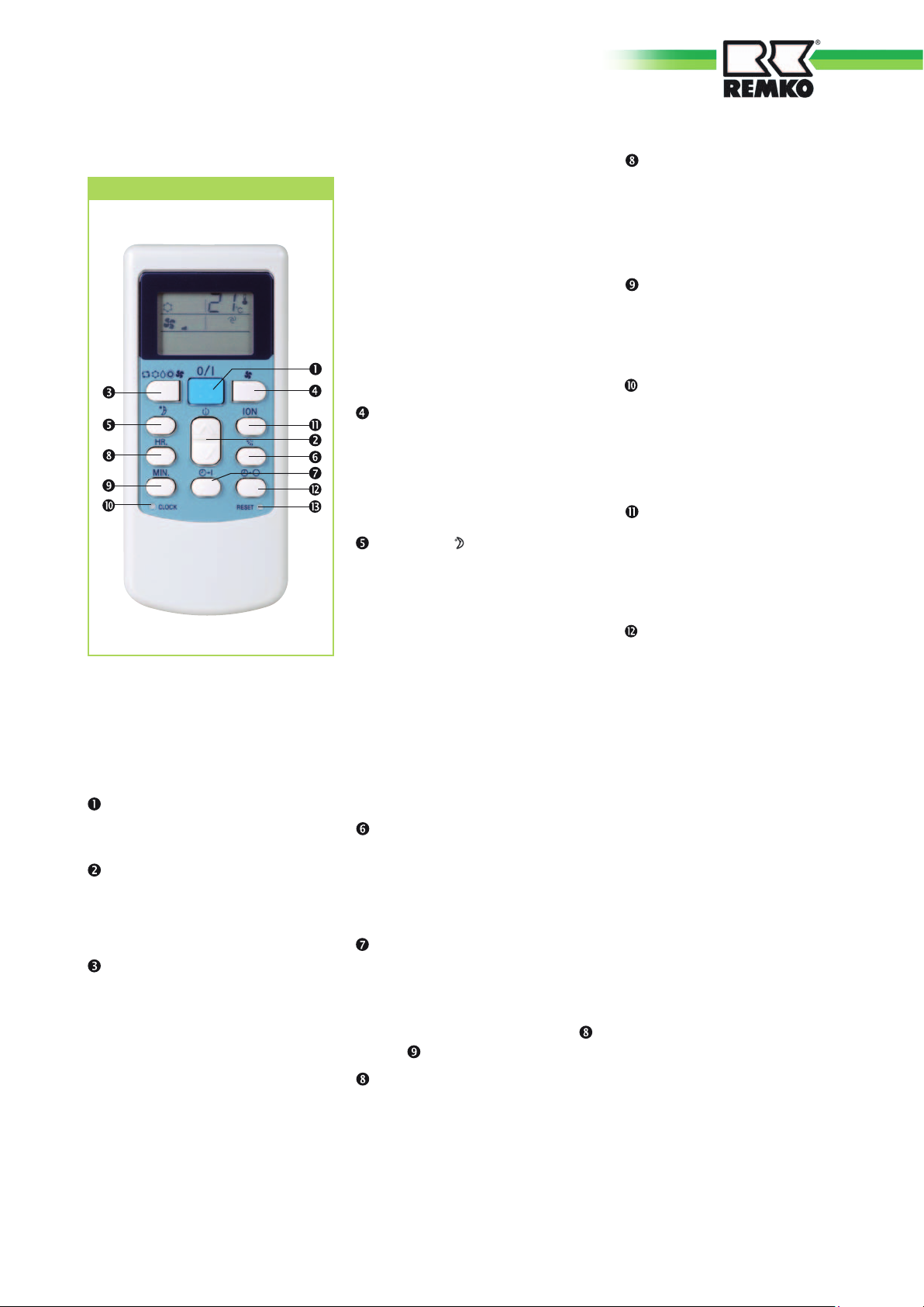
Buttons on the remote control
3. Heating mode In this mode,
the warm air in the room
is warmed to the desired
temperature.
4
. Air circulation mode
In this mode, the air in the room
is recirculated.
"MIN."button
This button increases the
minute value for time and timer
programming.
Buttons on the remote control
"ON/OFF" Button
Press this button
to start the unit.
" "button
This button is used to set
the desired temperature
between 18°C and 30°C.
"MODE"button
Use this button to select the
operating mode. The indoor unit
has 5 modes:
1. Automatic mode
In this mode, the unit works in
cooling or in heating mode.
2. Cooling mode
In this mode the cold air in the
room is cooled to the desired
temperature.
5
. Dehumidification mode
In this mode the room is mainly
dehumidified and the adjusted
temperature is maintained.
"FAN" button
Press this button to set the
desired fan speed. 4 speeds
are available: Automatic, high,
medium and low fan speed.
"(SLEEP)" button
After pressing this button,
the Sleep mode is activated
and in cooling operation, the
nominal temperature increases
automatically by 1 °C within
an hour, in heating operation,
the nominal temperature is
lowered by 1 °C within an
hour. After the second hour,
the temperature is increased/
lowered by 2°C. After 6 hours,
the function is switched off.
"(SWING)"button
This button directly activates
the oscillating function of the
fins for better air distribution
in the room.
"TIMER ON"button
This button is used to
activate the automatic on and/
or off time of the unit and
is programmed with buttons
and at intervals of 10
minutes.
"HR"button
This button increases the
hour value for time and timer
programming.
"CLOCK"button(recessed)
By pressing this button, the
time setting is activated.
"ION" button
By pressing this button, the ion
generator and turbo mode are
activated.
"TIMER OFF" button
This button serves to program
the automatic switch-off time
for the unit within the next 24
hours.
"RESET" button
(recessed)
This button resets the remote
control to its factory default
configuration.
7

REMKO ATY
Button functions
A symbol is shown on the display to indicate that the settings are being transferred.
ON/OFF Button
/ Button
By pressing the ON / OFF button, you can activate or deactivate your
unit. The programmed settings and adjustment values before the unit
was turned off will appear on the display.
ON/OFF ON/OFF
The remote control has its own temperature display. If buttons / are
pressed alternately, the display changes to . The button can be used
to reduce the desired nominal temperature, the button can be used
to increase it. This adjustment is only possible in coolingand heating
mode. In automatic mode, the fixed temperature of 24°C is preset.
The current setting is shown next to the temperature display.
In dehumidification mode, no temperature adjustment can be made.
MODE Button
Cooling /
mode
heating
Use the MODE button to select between the individual operating modes.
5 modes are available:
1. Automatic automatic selection of cooling or heating operation
2. Cooling predominantly summer operating mode
3. Dehumidification Summer or winter operating mode
4. Heating predominantly winter operating mode
5. Air circulation only for circulation of air
Automatic Cooling
MODE
Dehumidifying
MODE MODE MODE MODE
Heating
Air circulation
8

AUTOMATIC MODE
In automatic mode, the controller autonomously selects between heating
and cooling operation when the unit is first turned on. A nominal
temperature of 24 °C is preset.
Cooling MODE
MODE
AUTOMATIC
In cooling mode, the air in the room is cooled down to the set nominal
temperature. The desired room temperature is set with the ▲/▼buttons
in 1 °C increments. If the room temperature is 1 °C above the selected
nominal temperature, the indoor unit starts to cool the air in the room.
The inverter controller checks the difference between the adjusted
nominal temperature and the actual room temperature. If there is a large
difference, the cooling output is very high. If the difference is smaller,
a lower cooling output is produced. This serves to maintain the air
discharge temperature and the room temperature.
If the adjusted room temperature is lower than approx. 2 °C, then the
control system turns the cooling function off. To protect the compressor,
the controller only turns the cooling on again after a waiting period
of 3 minutes.
MODE
COOLING OPERATION
Functional diagram
Nominal temperature
Nominal temperature -2°C
Compressor operation AT
Fan operation AT
Fan operation IT
Actual temperature
> 6 Min.
> 6 Min.> 3 Min.
30 sec. 30 sec.
Start cooling mode
Cooling mode
Stop cooling mode
Operation
Stop
9

REMKO ATY
Heating MODE
In the heating mode, you can heat the room in spring or fall. The desired
room temperature is set with buttons / in 1 °C increments. If the
room temperature is 1 °C below the selected nominal temperature, then
the indoor unit starts to warm up the air in the room. If the adjusted
room temperature is exceeded by approx. 0.5°C, then the controller
turns the heater function off. To protect the compressor, the controller
will not switch the heating on again until
it has waited for 3 minutes.
MODE MODE
HEATING
OPERATION
Functional diagram
Nominal temperature +5
Nominal temperature +2
Compressor operation AT
Fan operation AT
Fan operation IT
Reverse flow valve
Actual temperature
°C
°C
> 6 Min.
> 6 Min.> 3 Min.
30 sec. 30 sec.
30 sec. 30 sec.
Stop heating operation
Heating mode
Start heating mode
Operation
Stop
Air circulation MODE
During the defrosting cycle, the indoor unit vaporiser fan and
the outdoor unit condenser fan are switched off.
After the cycle is concluded, the fans are switched to their previous
settings.
Reverse flow valve
Compressor operation AT
Fan operation AT
Fan operation IT
Defrost period
30 sec.
< 7 Min.
15 sec.
30 sec.
60 sec.
30 sec.
3 Min.
Operation
Stop
In the air circulation mode, the air in the room is only circulated.
The room temperature cannot be changed in this mode. The cooling
or heating operation is not activated. The fan has four speeds. Neither
the ion generator nor turbo mode can be selected in this mode.
MODE
AIR CIRCULATION
10

Dehumidification MODE
In dehumidification mode, the room temperature cannot be set. Due
to the low temperature of the refrigerant, the dew point of the air at the
condenser is undercut. The excess moisture in the air is condensed on the
condenser, the room is dehumidified. The fan has four speeds. Neither
the ion generator nor turbo mode can be selected in this mode.
FAN Button
MODE
DEHUMIFICATION
MODE
Functional diagram
Nominal temperature
Nominal temperature -2°C
Compressor operation AT
Fan operation AT
Fan operation IT
Actual temperature
Low fan speed
Start
Dehumidifying mode
Dehumidifying mode
Stop
Dehumidifying mode
30 sec.
Operation
Stop
The fan speed can be adjusted with this button. A selection can be made
between low, medium, high and automatic fan speed.
FANFANFAN FAN
CLOCK Button (recessed)
NOTE
The speed change is achieved with a phase control. When switching
between individual speeds, virtually no audible difference is
noticeable.
The time can be programmed by pressing the CLOCK button. The time
blinks in the display and the current time can be set using the HR. and
MIN. button. Programming is completed by pressing the CLOCK button,
the display will stop blinking.
CLOCK
HR./MIN.
CLOCK
11

REMKO ATY
SWING Button (covered)
SLEEP Button
The oscillating function of the air discharge fins can be adjusted with this
butto. This makes it possible to switch directly between a fixed position
and the oscillating function. The air distribution in the room is improved
using the swing function.
This button activates a programming function, which causes the
nominal temperature in cooling mode to increase after one hour by 1°C
and after two hours by 2 °C. In heating mode, the nominal temperature
is decreased after one hour by 1°C and after 2 hours by 2°C . In this
function, the fan is in automatic mode.
SLEEP
TIMER Button
Functional diagram
1st
hour
2nd
Nominal temperature +2
Nominal temperature +1°C
unit operation
Nominal temperature -1
Nominal temperature -2
°C
°C
°C
hour
1st hour 2nd hour 6th hour
6th
hour
Opera
Stop
tion
The turn on and turn off time can be programmed with this button.
By pressing the TIMER button several times, the turn on, the turn
off and the combined turn on and off timer is activated. The turn on
or turn off time blinks. The timer display on the indoor unit illuminates.
The desired turn on or turn off time is set by pressing the buttons HR.
and MIN. After completed adjustment, the timer symbol will continue
to blink for approximately 15 seconds. When the programmed time
has been reached, the unit automatically switches on or off. If the unit
is automatically switched on, the mode, temperature and fan speed for
the last setting are activated. The prior deletion of the on and off time
is made by pressing the corresponding timer button. The timer display
on the indoor unit goes out.
12

PROGRAMMINGTIMER ON
The controller turns the unit on after programming. During operation,
all settings can be seen on the display. Out of operation, only the timer
settings are visible.
PROGRAMMING TIMER OFF
PROGRAMMING TIMER ON/OFF
Timer on
HR/MIN
30 sec.
The controller turns the unit off after programming. During operation,
all settings can be seen on the display. Out of operation, only the timer
settings are visible.
Timer off HR/MIN 30 sec.
The controller turns the unit on or off after programming. In operation,
all settings are visible on the display. Out of operation, only the timer
settings are visible.
Unit On Unit Off
Example:
The controller turns on at 10:20.
The unit is in operation until 05:00.
13

REMKO ATY
INDOOR UNIT DISPLAY
SET
TURBO
C
By pressing the "ION" button several times, the "ION" function,
the "Turbo" function, or both can be set at the same time.
Ion function
The unit is equipped with an ion generator to generate negative ions.
A high concentration of negative ions is found for example in mountains,
near waterfalls and in forests and people perceive this inhaled air as
"clean". Only a slight ion concentration is found in interior rooms. In this
case, the ion generator can enhance the ions to the oxygen molecules
of the surrounding air and can increase the feeling of well-being. In
addition, atmospheric particles and dust particles in the air are bound,
naturally cleaning the air. Any dust can settle on smooth surfaced due
to the ionization and can be removed manually. Weekly cleaning of the
housing and the filter should be observed when using the ionization
feature. The function is available in all operating modes.
Turbo function
With this button, the air volume flow in cooling and heating operation
is increased for 30 minutes. This makes it possible to cool off or warm
up a room quicker. The ventilation and dehumidification mode cannot
be obtained, the system changes to automatic mode.
After 30 minutes, the controller returns to the last programmed settings.
SET
TURBO
C
14

Shutdown
Care and maintenance
Temporary
Shutdown
1. Allow the indoor unit to run for 2
to 3 hours in air circulation
mode or in cooling mode at the
maximum temperature setting
in order to remove any residual
moisture from the unit.
2. Shut down the unit using the
remote control.
3. Switch off the voltage supply
to the unit.
4. Check the unit for visible
signs of damage and clean as
described in the chapter "Care
and maintenance".
Permanent
Shutdown
Ensure that equipment and
components are disposed
of in accordance with local
regulations, e.g. using certified
firms and recycling specialists or
at collection points.
REMKO GmbH & Co. KG or your
contractual partner will be pleased
to provide a list of certified firms
near you.
Regular care and maintenance
serves to ensure trouble-free
operation and long service life
of the unit.
CAUTION
Prior to performing any work,
ensure the equipment is
disconnected from the voltage
supply and secured to prevent
accidental switch-on!
Care
■
Ensure the indoor unit and
outdoor component are
protected against dirt, mould
and other deposits.
■
Clean the equipment using
a damp cloth. Do not use any
caustic, abrasive or solventbased cleaning products. Do
not use a jet of water.
■
Before an extended shut down
period, clean the fins on the
outdoor unit and cover the
outdoor unit with plastic to
avoid infiltration of dirt into
the unit.
Maintenance
■
We recommend concluding
a maintenance contract
with annual service from an
appropriate specialty company.
NOTE
This ensures the operational
reliability of your system!
NOTE
Statutory regulations require
an annual leak test for the
refrigerant circuit in relation to
the refrigerant filling capacity.
Inspection and documentation
is to be carried out by
specialty technicians.
Cleaning the housing
of the indoor unit
1. Disconnect the supply voltage
to the equipment.
2. Clean the unit with a soft damp
cloth.
3.
Switch the supply voltage back on.
CAUTION
Care and maintenance work
may only be carried out if the
unit is disconnected.
Air filter for indoor unit
Clean the air filter at intervals of
no more than 2 weeks. Reduce this
interval in case of heavily soiled air.
Cleaning the filter on
the indoor unit
The indoor unit is equipped with
a filter with antibacterial coating.
The filter cleans the air of dust and
thereby reduces the distribution of
bacteria.
15

REMKO ATY
1. Switch the indoor unit via the
remote control to air circulation
(the front cover of the air inlet
must be open!) (Figure 2).
Type of task
Checks/Maintenance/Inspections
2. Open the lower display cover
on the front side of the unit
by pressing both latches
and carefully fold the cover
downward and remove it from
the bracket (figure 3).
3. Push the clips on the filter up
and pull it out on the clips
(figure 4).
4. Clean the filter with a standard
vacuum cleaner. Turn the dirty
side upward (figure 5).
5. Carefully clean off any dirt in
lukewarm water and with mild
cleaner. Turn the dirty side
downwards (figure 6).
6. If water is used, let the filter dry
out air before replacing it in the
unit.
General
Measure voltage and current
Check function of compressor
Check fan function
Contamination of evaporator fins
Check refrigerant fill quantity
Check condensation drain
Test insulation
Check moving parts
Sealing test for refrigerant circuit
1) see note S.15
2 Open front cover
Commissioning
Monthly
Six-monthly
Yearly
• •
• •
• •
• •
• •
• •
• •
• •
• •
• •
Cleaning the condensation
pump (accessories)
An optional integrated or separate
condensation pump may be included
with the indoor unit, which pumps
out any accumulated condensation
into higher positioned drains.
Observe the care and maintenance
instructions given in the separate
operating instruction manual.
1)
7. Carefully insert the filter. Make
sure it is seated correctly.
8. Close the display cover as
described above but in reverse
order.
9. Set the desired operating mode.
4 Pull out the filter
5 Cleaning using a vacuum cleaner 3 Remove the display cover
6
Cleaning with lukewarm water
16
Troubleshooting and customer service
The equipment and components are manufactured using state-of-the-art production methods and tested several times
to verify their correct function. If malfunctions should occur, please check the functions as detailed in the list below. Please
inform your dealer if the unit is still not working correctly after all the functional checks have been performed!
Fault
Fault Possible cause Checks Remedial measures
The unit does not start
or switches itself off
continually.
The unit does not respond
to the remote control
Power failure, low voltage, main
fuse defective / main switch
turned off.
Power line damaged.
Waiting time after turn on too
short.
Operating temperature fallen
below / exceeded.
Power surge due to thunderstorm.
Problem of external condensation
pump.
Transmission distance too large /
receiving problem.
Remote control is defective.
Receiver and transmitter are
exposed to too much sun exposure.
Electromagnetic fields disrupt the
transmission.
Button of remote control stuck /
dual button control.
Are all other electrical installations
functioning correctly?
Are all other electrical installations
functioning correctly?
Have approx. 5 minutes
elapsed since the restart?
Are the fans in the indoor unit
and outdoor component working
correctly?
Have there been lightning strikes
in the area recently?
Did the pump shut down due to
a fault?
Does the indoor unit beep when
pressing a button?
Is the unit running in manual
mode?
Does it function correctly in the
shade?
Does it function after removing
potential fault sources?
Does the "Send” symbol appear
on the display?
Check voltage if necessary wait
until turned on again.
Repair by a certified service centre.
Schedule longer waiting periods.
Observe temperature ranges of
indoor unit and outdoor unit.
Switch off the mains breaker and
switch it back on. Inspection by
certified service centre.
Check or clean the pump, if
necessary.
Reduce the distance to less than
6 m and change location.
Replace remote control.
Shade the transmitter and receiver.
Signal is not transmitted when
interference sources are operational.
Release the button / press only
one button.
The unit is running with
reduced or without
cooling output.
Condensation discharge
on unit.
Batteries of remote control are
discharged.
Filter is dirty / air inlet / outlet
opening is blocked by debris.
Windows and doors open.
Heating/cooling loads increased.
No cooling operation is set.
Fins of the outdoor unit are
blocked by foreign matter.
Leaks in refrigerant circuit.
Drain pipe of collector reservoir
plugged / damaged.
External condensation pump or
floater defective.
Non-discharged condensation is in
the condensation line.
Condensation cannot be
discharged.
Have new batteries been inserted?
Is the display incomplete?
Have the filters been cleaned? Clean filters.
Have there been any
constructional / applicationrelated changes?
Is the cooling symbol activated
in the display?
Is the fan on the outdoor component
running outdoor component. Are the
evaporator fins clear?
Is frost formation visible on connections
of the outdoor unit?
Is unrestricted condensation discharge
ensured?
Is the collection tray full of water
and the pump not running?
Has the condensation pipe been
laid on a slope and is not blocked?
Are the condensation lines
unblocked and laid on a slope? Are
the condensation pump and float
switch functioning correctly?
Insert new batteries.
Close windows and doors / install
additional systems.
Correct the settings for the unit .
Check fan or winter regulation,
reduce air resistance.
Repair by certified service centre.
Cleaning of drain pipe and
collector reservoir.
Have pump replaced by certified
service centre.
Route the condensation line
downward or clean it.
The condensation line must have
a fall. If necessary, clean the pipe.
A faulty condensation pump and
float switch should be replaced.
17

REMKO ATY
Problem display by blinker code
LED in AT
No.
No.
Display
16
red
yellow
ER01 flashes - - -
ER02 flashes - - -
ER03 flashes - - -
ER04 flashes - - -
ER05 flashes - - -
ER06 flashes - - -
ER07 flashes - - -
ER08 flashes
ER09 flashes
ER10 flashes
ER11 flashes
ER12 flashes
ER13 flashes
ER14 flashes
ER15 flashes
ER16 flashes
ER18 flashes
ER19 flashes
ER20 flashes
O • •
• O •
O O •
O • O
• O O
× • •
• • ×
O • ×
× O •
× O O
× × ×
× × •
17
No.
Fault description Checks Remedial measures
18
green
Air circulation sensor on
indoor unit is defective /
triggered
Indoor unit power supply
defective
Frost protection sensor on
indoor unit faulty/tripped
Vaporiser fan motor speed
too low / defective
EEPROM indoor unit control
board error
Communication error
between IT and AT
Refrigerant fill quantity
incorrect
AT condenser sensor faulty /
tripped
Communication error
between IT and AT
Compressor speed too low
Over-current error
PFC error
Inverter-control board
communication error
Inverter board safety shut-off
Indoor unit outdoor air sensor
defective
Compressor temperature too
high
EEPROM Outdoor unit
control board error
Compressor start error
Outdoor unit system error
Check resistance (see p. 19) Replace defective sensor
Check power supply Repair power supply
Check resistance (see p. 19) Replace defective sensor
Check fan motor, fan blade Replace motor or blade
Check refrigerant pressure.
Check resistance (see p. 19) Replace defective sensor
Check wiring and connections
Check cable connections, pipe connections,
shut-off valves, compressor
Check voltage, cable connections,
refrigerant pressure, ambient conditions
Check cable connections, pipe connections,
shut-off valves, compressor
Check cable connections, pipe connections,
shut-off valves, compressor
Check cable connections, pipe connections,
shut-off valves, compressor
Check resistance (see p. 19) Replace defective sensor
Check condenser for dirt, check refrigerant
pressure Check fan
Check cable connections, pipe connections,
shut-off valves, compressor
HL
OT
OP
OD
OH
• × ×
O × •
× × O
× • O
× O ×
O × ×
Incorrect setting type for unit Contact specialist firm
Power supply fault
Ambient temperature too
high
Liquid temperature too high
Hot gas temperature too high
Inverter board overheat
• = Off O = On × = flashes
18
Check voltage, cable connections,
refrigerant pressure, ambient conditions
Switch unit off, switch unit back on when
ambient temperature is lower
Check condenser for dirt, check refrigerant
pressure Check fan
Check condenser for dirt, check refrigerant
pressure Check fan

Controller, safety controller and resistance
Hot gas sensor, IPM AT sensor
Temp.
0 160.73 kΩ
5 125.57 kΩ
10 98.78 kΩ
15 78.23 kΩ
20 62.35 kΩ
25 50.00 kΩ
30 40.33 kΩ
Resistance
AT condenser sensor, AT ambient temperature sensor
IT vaporiser sensor, IT circulation sensor
Temp.
0 27.42 kΩ
5 22.15kΩ
10 18.00 kΩ
15 14.72 kΩ
20 12.10 kΩ
25 10.00 kΩ
30 8.31 kΩ
Resistance
AT compressor
Temp.
Resistance
20 0.71 Ω
Measuring
point
U-V
V-W
U-W
Compressor control by via gas temperature Compressor control via vaporiser temperature
Hot gas tempera-
ture
< 87°C
93°C - 97°C no change to frequency
97°C - 110°C
> 110°C
Normal operating condition
decrease in frequency 1Hz/3sec.
Controller
control via IT
Switch off compressor
IT surface tempera-
ture
> 6°C
< 6°C no change to frequency
< 4°C decrease in frequency 1Hz/3sec.
< 1°C Switch off compressor
Cooling regulation
Normal operating condition
control via IT
Compressor control via ambient temperature
Ambient temperature
> 53°C Frequency 32Hz
47°C - 53°C Frequency 50 Hz
39°C - 47°C Frequency 70Hz.
15°C - 39°C
< 15°C Frequency 32Hz
Cooling mode regulation
Normal operating condition
control via IT
Compressor control via ambient temperature
Ambient temperature
> 23°C Frequency 32Hz
19°C - 23°C Frequency 50 Hz
12°C - 19°C Frequency 70Hz.
< 12°C
<-25°C or >+70°C Switch off compressor
Heating mode regulation
Normal operating condition
control via IT
Compressor control via vaporiser temperature
IT surface tempera-
ture
< 51°C
51°C - 55°C no change to frequency
55°C - 65°C decrease in frequency 1Hz/3sec.
> 65°C Switch off compressor
Heating regulation
Normal operating condition
control via IT
Compressor control via power consumption
Power consumption
> 6.1 A no change to frequency
6.2 - 6.7A decrease in frequency 1Hz/3sec.
6,7-7,5 Switch off compressor
Cooling / heating regulation
19

REMKO ATY
Installation instructions for qualified personnel
Important notes prior to
installation
NOTE
The assembly and installation
of the units and components
may only be carried out by
especially trained technicians.
■
Transport the unit in its original
packaging as close as possible
to the installation location.
You avoid transport damages
by doing so.
■
Check the contents of the
packaging for completeness
and check the unit for visible
transport damage. Report any
damage immediately to your
contractual partner and the
shipping company.
■
Lift the unit at the corners
and not by the refrigerant or
condensation connections.
■
The refrigerant pipes
(injection and suction line),
valves and connections must
be insulated against vapour
diffusion. If necessary, also
insulate the condensation pipe.
■
Select an installation location
which allows air to freely
flow through the inlet and
outlet. (See section "Minimum
clearances").
devices with intensive thermal
radiation. Installation near
sources of thermal radiation
reduces the output of the unit.
■
Only open the shut-off valves
of the refrigerant lines after
the installation is complete.
■
Before connecting the injection
line, remove the valve core
in the indoor unit connection
ports.
■
Seal off open refrigerant lines
with suitable caps or adhesive
strips to avoid infiltration of
moisture and never kink or
compress the refrigerant lines.
■
Avoid unnecessary bends.
In doing so, you minimise loss
of pressure in the refrigerant
lines and ensure clear return
flow of the compressor oil.
■
Take special precautions with
regard to the oil return if the
exterior component is located
above the indoor unit. (See
section "Oil return flow
measures").
■
If the basic length of the
refrigerant line exceeds
5 metres, add refrigerant.
The quantity of additional
refrigerant is provided in
the chapter "Add refrigerant".
■
Only use the union nuts for the
refrigerant pipes included in the
delivery, and remove them only
shortly before connecting the
refrigerant lines.
■
Make electrical connections
in accordance with the effective
DIN and VDE standards.
■
Always fasten electric cables
properly to the electrical
terminals. Otherwise a fire
could result.
■
Do not install the unit in
the immediate vicinity of
20

Wall openings
Selection of the installation location
Wind
■ A wall opening of at least
70 mm diameter and 10 mm
slope from the inside to the
outside must be made for each
indoor unit.
■ We recommend that the inside
of the opening is padded or
lined, e.g. using a PVC pipe,
to prevent the lines being
damaged.
■ After installation, the wall
opening should be closed off
with a suitable sealant. Do not
use materials containing cement
or lime!
Lines in the wall throughput
Control line
The indoor unit is designed for
horizontal wall installation in the
upper wall area (at least 1.75
m from the upper edge - floor).
However, it can also be used in the
upperwall area above doors.
The outdoor component is
designed for horizontal installation
on a base in outdoor areas. It
should be placed on level, flat and
firm surface. The unit should also
be secured to prevent toppling.
The outdoor unit can be set up
outside as well as inside a building.
For external installation, please
observe the following notes to
protect the unit from weather
conditions.
Rain
If the unit is being installed in
windy areas, ensure that the
warm outlet air discharges in the
main wind direction. If this is not
the case it may be necessary to
install a windbreak (provided by
the customer). Ensure that the
windbreak does not adversely
affect the air intake to the unit.
Windbreak
Wind
PVC tube
Suction line
Condensation line
Injection line
Installation material
The indoor unit is attached with
4 screws on the building side,
through the back wall of the unit.
The outdoor unit is attached with
4 screws via a wall bracket on
the wall or a floor bracket on the
ground.
NOTE
Install the outdoor unit
with appropriate anchors,
depending on the type of wall.
The unit should be at least 10 cm
off the ground when mounted on
the roof or ground. A pedestal is
available as an accessory.
Sun
The evaporator fins (condenser)
of the outdoor unit are the
heat discharge components in
cooling operation. Exposure to
direct sunlight further increases
the temperature of the fins and
so reduces the heat released by
the finned heat exchanger. The
outdoor component should be
installed on to the north side of
the building whenever possible.
If necessary, take measures
to provide sufficient shade
(responsibility of customer).
This could be a small roof.
However, the discharging warm air
flow may not be affected by the
measures.
Snow
The unit should be wall-mounted
in areas of heavy snowfall.
Installation should then be at least
20 cm above the expected level
of snow to prevent snow from
entering the outdoor component.
An optional wall bracket is
available as an accessory.
Minimum clearance to snow
Snow
20 cm
21
REMKO ATY
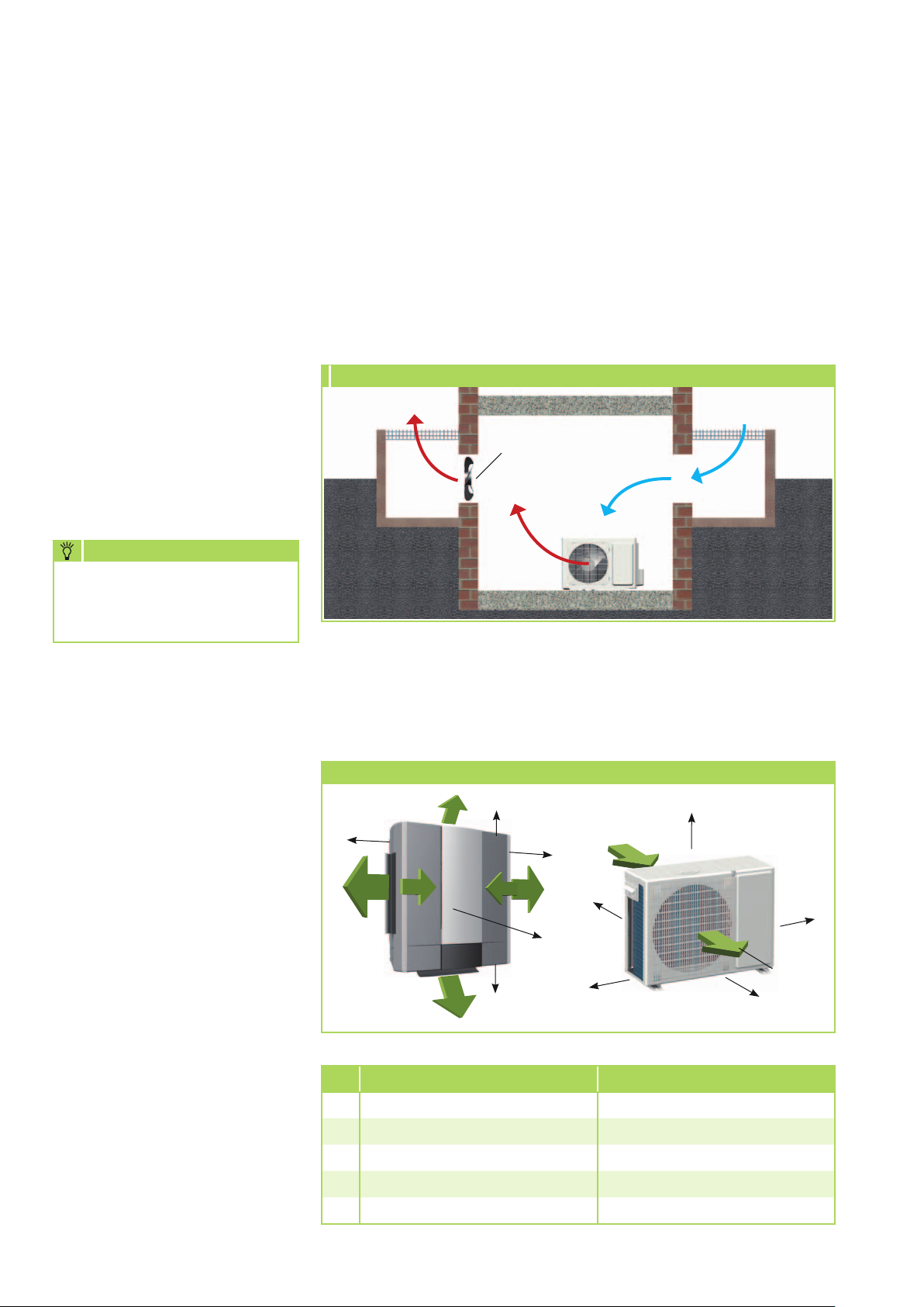
Installation inside buildings
■
Ensure that heat can dissipate
adequately when placing the
outdoor component in cellars,
attics, adjoining rooms or halls
(figure 7).
■
Install an additional fan with
a rated flow comparative to
that of the outdoor component
being installed in the room.
This is used in conjunction with
ventilation ducts to compensate
any pressure losses (figure 7)
NOTE
■
Ensure a continuous and
unobstructed air flow from
outside, preferably using
sufficiently large air intakes
placed opposite each other
(figure 7).
7 Installation inside buildings
Warm air
Additional
fan
Light
well
Warm air
■
Comply with any regulations
and conditions affecting the
structure of the building.
If necessary, fit acoustic
installation.
Outdoor component
Cold
Fresh air
Light
well
In heating mode, condensation
formation may occur due to
cold surfaces.
Minimum clearances
Observe the minimum clearances
to allow access for maintenance
and repair work and facilitate
optimum air distribution.
Minimum clearances
1000
300
1000
1000
1000
Air intake
D
A
E
C
Air
discharge
B
22
ATY 261 DC AT ATY 351 DC AT
A 100 mm 100 mm
B 700 mm 700 mm
C 400 mm 400 mm
D 100 mm 100 mm
E 300 mm 300 mm

Installation
Oil return measures
If the outdoor unit is installed at
a higher level than the indoor unit,
we recommend that suitable oil
return measures are taken. Usually
an oil pump bend is installed
for every 2.5 metres of height
difference.
Oil return measures
Outdoor component
Oil pump bend
in suction pipe to
outdoor component
1 x every 2.5 metres
of rise in the line
max. 5 m
NOTE
Installation may only be
performed by authorised
specialists.
Unit installation
When attaching the indoor unit,
pay attention to the lower, upper
and side area air discharge.
1. Use the dimensions of the
unit to mark the fixing points
on structural parts approved
to support the static load.
2. Open the display cover(figure 8)
and remove the two screws from
underneath the filter (figure 9).
8
Open display cover
9
Remove screws
Radius:
50 mm
Outdoor component
Connection variations
of indoor unit
Connection variations
1
2
1 Outlet on the wall, right
2 Outlet through the wall, right
3 Outlet through the wall, left
4 Outlet on the wall, left
View from the rear
3. Remove the front of the unit
by lifting the front in the lower
area from the body approx.
10 cm and folding it upward
(figure 10).
4. Pull the plugs of the front cover
from the circuit board (figure 11).
5. Remove the housing's break
out opening if necessary.
6. nstall the unit on the wall.
Ensure undistorted installation.
7. Connect the refrigerant
4
3
lines, electrical cables and
condensation line to the indoor
unit as described below.
8. Check that the unit is level.
9. Re-assemble the unit.
10
R
elease unit front
11
Remove the plug
Installation of the indoor unit
The wall bracket for the unit must
be attached with suitable screws
and anchors.
23

REMKO ATY
Connecting the
refrigerant lines
The on-site connection of the
refrigerant lines is undertaken
inside the unit.
It may be necessary to fit a reducer
or flared adapter to the indoor
unit. These fittings are included
with the indoor unit as an
accessory kit. Once installed, the
connections should be sealed to
prevent vapour diffusion.
CAUTION
The units are factory filled with
dry nitrogen to check for leaks.
The pressurised nitrogen is
released when the union nuts
are loosened.
The following instructions describe
the installation of the refrigerant
circuit and the assembly of the indoor
unit and the outdoor component.
1.
Check the "Technical Data"
chart for the required pipe
diameters and connect the
refrigerant line.
2. To bend the copper tubing, use
the appropriate bending tool to
prevent kinks in the tubing.
3. Observe the permitted bending
radius for the refrigerant pipes
during installation. Never bend
a pipe twice in the same place.
Brittleness and cracking can
result.
4. Lay the refrigerant lines from
the indoor unit to the outdoor
component. Ensure that the
fastenings are adequate and if
necessary, take appropriate oil
return measures!
5. Use the wall or floor brackets
to fit the outdoor component
against structural parts
approved to support the static
load (refer to the installation
instructions for the brackets).
6. Ensure that structure-borne
sound is not transferred to parts
of the building. Use vibration
dampers to reduce the effects
of structure-borne sound!
7. Remove the factory-fitted
protective caps and the union
nuts from the blocking valve
connections and use them for
further installation.
8. Before flanging the refrigerant
lines, ensure that the union nut
is on the pipe.
9. Prepare the refrigerant lines as
shown below
(figure 12+13, page 23).
10.
Check if the flange has the
correct shape
(figure 14, page 23).
11 Before connecting the injection
line, remove the valve core
in the indoor unit connection
ports.
12.
First connect and hand-tighten
the refrigerant connections
to ensure they are correctly
seated.
13.
Now fully tighten the fittings
using 2 suitably sized openended spanners.
Use one spanner to counter
the force when tightening the
fitting (figure 15, page 23).
14.
Apply appropriate heat
insulation to both installed
refrigerant lines, including
connector.
15.
Only use insulating hoses
suitable and diffusion-safe or
the temperature range.
NOTE
Use only tools which are
approved for use in an HVAC
environment. Pipe cutter,
deburrer, bending pliers and
flanging tool.
Supplementary information
for Installation
■
When combining the outdoor
component with some indoor
units, the connection of the
refrigerant pipes may differ.
In that case, install the provided
reducer or expansion fittings to
the indoor unit.
■
If the basic length of the
refrigerant line exceeds
5 m, add refrigerant when
commissioning the system for
the first time. (See chapter
"Add refrigerant").
24

Monitoring for leaks
12 Deburring the refrigerant line
Refrigerant line
Deburrer
13 Flanging the refrigerant line
Flanging tool
14 Correct flange shape
Once all the connections have
been established, the pressure
gauge station is attached as
follows to the Schrader valve
(if fitted):
red = small valve
= injection pressure
blue = large valve
= suction pressure
After completed connection, the
leakage test is carried out with dry
nitrogen.
CAUTION
Before the leakage test, the
pipe connections must be
checked.
The tightness test involves
spraying a leak detection spray
onto the connections. If bubbles
are visible, the connections have
not been properly made. Tighten
the connection or prepare a new
flange.
The time required to generate
the vacuum is dependent on
the pipework volume of the
indoor unit and the length of the
refrigerant lines. The process will
always take at least 60 minutes.
Once any foreign gases and
moisture have been completely
extracted from the system, the
valves on the pressure gauge
station will be closed and the
valves on the outdoor component
will be opened as described in the
chapter on "Commissioning".
15 Tighten fittings
Tighten 1st Spanner
Counter
2nd Spanner
Tightening
torque:
“
12 - 16 Nm
“
28 - 32 Nm
“
40 - 44 Nm
“
64 - 68 Nm
After successful leakage test, the
excess pressure in the refrigerant
lines is removed and a vacuum
pump with the absolute final
partial pressure of min. 0.01 mbar
is used to remove all the air and
empty the lines. Any moisture
present in the pipes will also be
removed.
NOTE
A vacuum of min. 0.05 mbar
must be created!
25

REMKO ATY
Condensate drain
Due to the dew point shortfall
on the vaporiser, condensation is
created on the indoor unit during
the cooling operation and on the
outdoor unit during the heating
operation.
Below the vaporiser is a collection
tray, which must be connected to
a drain.
■
The condensation line is to
be installed with a minimum
slope of 2 %. (figure 11).
If necessary, fit vapour diffusion
tight insulation.
■
Lead the condensation line
freely to the run-off line. If
the condensation runs directly
into a sewer pipe, fit a trap to
prevent any unpleasant odours.
■
When operating the unit at
outdoor temperatures below
0°C, ensure the condensation
pipe is laid to protect it
against frost. If necessary, fit
supplementary pipe heating.
■
After completed installation,
check for unobstructed
condensation run off and
ensure that a permanent seal
is provided.
The condensation hose is designed
to be installed on the right and the
left side (view from front). Remove
the plug at the corresponding
connection.
Indoor unit condensation connection
50
65
40
45
Condensate drain
right or left
Electrical connection
Mains cable must be installed as
voltage supply to the indoor unit
and a control cable to the outdoor
component, with appropriate
safeguards.
■
We recommend installing a
main / repair switch on the
building near to the indoor unit.
■
Power is supplied to the
indoor unit, the outdoor unit
is supplied via a control line
from the indoor unit.
■
The terminal blocks for making
the connections are located
behind the cover on the
outdoor component.
■
If an optionally available
condensation pump is used
on the unit, then an additional
relay for the shut-off contact
of the pump will be needed to
increase the switching power
to shut off the compressor.
■
Control cables should be
screened if laid in areas exposed
to strong magnetic fields.
16
Slope of the condensation line
26
at least
2% fall
Condensation connection - outdoor component
Opening for
Condensate drain
Condensation tray
for the outdoor unit.
NOTE
A condensation pump cannot
be installed within the units.
■
Electrical protection is provided
in accordance with the technical
data.
CAUTION
All electrical installation work
is to be performed by specialty
companies. Disconnect the
voltage supply when connecting
the electrical terminals.

Connecting the indoor unit Figure 17
Connecting the outdoor
component
Proceed as follows to connect the
cable:
1. Remove the cover from the
unit.
2. Remove the side panel next to
the terminals.
Terminal bar /
control bar
Mains cable
Before connecting the refrigerant
piping, the valve core must be
removed from the injection line.
3. Feed the cables through the
ferrite core supplied in the
delivery (figure 17+18).
4. Feed the cable through the
edge protection ring of the
fixed connection plate.
5. Connect the cable as shown
on the electrical connection
diagram.
6. Anchor the cable in the strain
relief and re-assemble the unit.
Check all plugged and clamped
terminals to verify they are seated
correctly and make a permanent
contact. Tighten as required.
Figure 18
Connecting the indoor unit
Make the connection as follows:
1. Remove the front of the unit,
as described in chapter "Unit
installation" .
2. Select the cable cross-section
according to the relevant
standards.
Electrical connection diagram
ATY 261 DC / ATY 351 DC
Outdoor
component
Exterior conductor
A
B
Neutral conductor
C
Control conductor
D
PE
Earth conductor
the indoor unit
Exterior conductor
L
1N
Earth conductor
PE
1
2
3
4
PE
Mains cable
L1
N
PE
230 V~,
50 Hz,
L1 / N
/ PE
3. Connect the unit to the mains
cable and control cable on the
outdoor component.
(See electrical connection
diagram).
4. Re-assemble the unit.
27
U
V
W
U
V
W
REMKO ATY
Electrical circuit diagram
ATY 261 DC AT / ATY 351 DC AT
■
Check the refrigerant lines and
insulation for damage.
L in
W
U
Compressor
W
VV
U
A = Reverse flow valve
B = Condenser fan
IPM
Sensor
IPM inverter power drive
N out
P out
A
B
J1
P
N
ATY 261 DC IT / ATY 351 DC IT
Swing motors
Lift motors
L
N
N
L
C
J4
N out
P out
P
N
Vaporiser
fan
J2
J1
N-Out
L-Out
Control board
E
COMM
AC N In
AC L In
Condenser
Ion generator
LDC
Pe
D
S
C
N
B
L
A
Terminal strip
Outdoor
component
Condenser
Test
Air-intake sensor
Condenser sensor
Hot gas sensor
AC N
AC L
4
3
2
1
Terminal strip
the indoor
unit
■
Check the electrical connection
between the indoor unit and
the outdoor unit for correct
polarity.
■
Check that all fastenings,
mountings etc. are firm and
at the correct level.
Add refrigerant
CAUTION
Wear protective clothing when
handling refrigerant.
Display
Air circulation sensor
Antifreeze sensor
Before commissioning
After successful leakage test, the
vacuum pump must be connected
using the pressure gauge station
to the valve connections of
the outdoor unit (see chapter
"Leakage test") to create
a vacuum.
Perform the following checks
prior to commissioning the
unit for the first time and after
Display
Pe
Mains cable
N
230/1Ph/50Hz
L
Button
manual operation
any interventions affecting the
refrigerant circuit. Record the
results in the commissioning
report:
■
Check all refrigerant lines and
valves with leak detection spray
or soapy water for leaks and for
inadvertent mix up of suction
and injection line. Perform this
check when the unit is not
running.
The equipment contains a
basic quantity of refrigerant.
Furthermore, for refrigerant line
lengths of more than 5 metres
per circuit, an additional amount
of refrigerant must be added,
Control line
in accordance with the following
chart:
ATY 261 DC
ATY 351 DC
Basic
line length
Additional fill quantity
Up to and
incl.
0 g/m
5 m
5 m to
max. 15 m
20 g/m
NOTE
Ensure that the refrigerant in
use is always replenished in
liquid form!
28

Commissioning
NOTE
Commissioning is only to be
performed and documented
by specially trained personnel.
Once all the components have
been connected and tested, the
system can be commissioned
. A functional check should be
performed to verify its correct
function and identify any unusual
operational behaviour prior to
handing it over to the operator.
Function test and
test run
Check the following points:
■
Leak tightness of refrigerant
lines.
■
Compressor and fan running
smoothly.
Function test of Cooling
operating mode
1. Remove the caps
from the valves.
2. Begin the commissioning
process by briefly opening the
shut-off valves of the external
unit until the manometer
displays a pressure of approx.
2 bar.
3. Use leak detection spray or
suitable devices to check that all
the connections are tight.
4. If no leaks are found, open
the stop valves by turning them
anti-clockwise as far as they will
turn using a hexagon spanner.
If leaks are found, draw off
the refrigerant and rework
the defective connection. It is
imperative that the vacuum
creation and drying steps are
repeated!
5. Switch on the mains switch
or circuit breaker.
9. Check the correct function
of the condensation line by
pouring distilled water into the
condensation tray.
A bottle with a spout is
recommended for pouring the
water into the condensation
tray.
10.
Switch the indoor unit to
cooling mode.
NOTE
Due to the turn on delay, the
compressor will start up a few
minutes later.
11.
Check the correct function and
settings of all control and safety
devices during the test run.
12.
Check the control system
in the indoor unit using the
functions described in the
operating manual.
(Timer, temperature settings
and all mode settings).
■
In cooling mode, cold air
output by the indoor unit, and
warm air output by the outdoor
component.
■
Functional test of the indoor
unit and all program sequences.
■
Check of the surface
temperature of the suction
pipe and determination of
vaporiser overheating. To
measure the temperature, hold
the thermometer to the suction
pipe and subtract the boiling
point temperature reading on
the pressure gauge from the
measured temperature.
■
Documentation of the
measured temperatures in the
commissioning report.
6. Use the remote control to
switch on the unit and select
the cooling mode, maximum
fan speed and lowest nominal
temperature.
7. Measure and record all
the required values in the
commissioning report and
check the safety functions.
8. Check the control system
for the unit using the
functions described in the
chapter "Operation". Timer,
temperature setting, fan speeds
and switching to circulating or
dehumidifying mode.
13.
Check the overheating,
outdoor, indoor, outlet and
vaporisation temperatures and
record the measured values
in the commissioning report.
14.
Remove the pressure gauge
and fit the sealing caps.
NOTE
Then, check the blocking
valves for leaks.
Final tasks
■
Reassemble all disassembled
parts.
■
Familiarise the operator with
the system.
29

REMKO ATY
Unit dimensions
ATY 261 DC AT / ATY 351 DC AT
623
265
ATY 261 DC IT / ATY 351 DC IT
148
720
567
245
532
All values in mm
470
567
47
45
396
25
All values in mm
We reserve the right to modify the dimensions and constructional design as part of the ongoing technical development process.
30
495

Technical data
Series ATY 261 DC ATY 351 DC
Operational mode Inverter-wall room air conditioner combination for cooling and heating
Nominal cooling output
Nominal heating output
Energy efficiency class, cooling EER
Energy efficiency class, heating COP
Energy efficiency ratio EER
Coefficient of performance COP
Power consumption, annual, (500h) K / H kWh 365 495
Operating range (room volume), approx. m³ 80 110
Refrigerant R 410A
Operating pressure, max. per cooling circuit kPa 3800/1200 3800/1200
Power supply V/Hz 230/1~/50 230/1~/50
Nom. electrical power consumption, cooling
Nom. electrical power consumption, heating
Elec. nominal power consumption cooling
Elec. nominal power consumption heating
Elec. starting current, max. A 20 25
Refrigerant connection - injection line
Coolant connection - suction line
Data specific to indoor unit
Operating range °C/ %r.F +16 to +32 / 80% +16 to +32 / 80%
Adjustment range - Cooling °C +18 to +30 +18 to +30
Adjustment range - Heating °C +16 to +28 +16 to +28
Air flow volume per speed setting m³/h 360/390/420 380/410/440
Protection class IP X0 X0
Sound pressure level per speed setting
Dimensions - height mm 567 567
Width mm 567 567
Depth mm 148 148
Weight kg 12,0 12,0
Corresponding outdoor component
Operating range - cooling °C +15 to +45 +15 to +45
Operating range - heating °C -7 to +24 -7 to +24
Air volume flow, max. K/H m³/h 1340 1890
Protection class IP X4 X4
Sound pressure level, max.
Refrigerant, basic quantity
Refrigerant, additional quantity > 5 m g/m 20 20
Refrigerant line, max. length m 15 15
Refrigerant line, max. height m 5 5
Dimensions - height mm 532 532
Width mm 720 720
Depth mm 245 245
Weight kg 37,0 38,0
Serial number 937... 938...
EDP no. 1624261 1624351
1) Air inlet temperature TK 27°C / FK 19°C, outdoor temperature TK 35°C, FK 24°C, max. air flow volume, 5m line length, according to DIN EN14511
2) Air inlet temperature TK 20°C, outdoor temperature TK 7°C / FK 6°C, max. air flow volume, 5m line length, according to DIN EN14511
3) Distance 1 m free field
4) Contains greenhouse gas according to Kyoto protocol
1)
2)
1)
2)
1)
2)
kW 2,69 (1,00-2,93) 3,52 (1,2-3,87)
kW 2,93 (1,00-3,20) 3,87 (1,20-4,10)
A A
A B
3,68 3,56
3,64 3,49
4)
1)
kW 0,75 0,99
2)
kW 0,81 1,11
1)
A 3,48 4,62
2)
A 4,00 5,21
Inches (mm)
Inches (mm)
1/4 (6,35) 1/4 (6,35)
3/8 (9,52) 1/2 (12,7)
R 410A
4)
ATY 261 DC IT ATY 351 DC IT
3)
dB(A) 33/36/40 35/37/41
ATY 261 DC AT ATY 351 DC AT
3)
4)
dB(A) 45 49
kg 410 A / 0.63 410 A / 0.83
31

REMKO ATY
Exploded view ATY 261 DC IT / ATY 351 DC IT
3
17
15
1
5
7
14
6
7
We reserve the right to modify
the dimensions and constructional design
as part of the ongoing technical
development process.
13
5
14
8
7
4
11
10
2
12
Spare parts list
No. Designation ATY 261 DC IT ATY 351 DC IT
1 Cover - air inlet 1107400 1107400
2 Cover - display 1107401 1107401
3 Air filter 1107402 1107402
4 Display board 1107470 1107470
5 Lift motor, set 1107404 1107404
6 Swing motor 1107405 1107405
7 Air outlet fins, set 1107406 1107406
8 Condensation tray 1107439 1107439
9 Fin vaporiser 1107409 1107486
10 Fan wheel, vaporiser 1107410 1107410
11 Fan motor, vaporiser 1107471 1107471
12 Control board 1107472 1107473
13 Ion generator 1107415 1107415
14 Housing angle, set (right & left) 1107416 1107416
15 Mounting clip - cover, set 1107417 1107417
16 Antifreeze sensor / air circulation sensor 1107418 1107418
17 IR remote control 1107474 1107474
16
9
When ordering spare parts, please state the computerised part no., unit number and type (see identification plate) !
32

Exploded view ATY 261 DC AT / ATY 351 DC AT
14
1
9
4
15
16
6
13
10
11
12
5
8
7
3
14
14
2
We reserve the right to modify
the dimensions and constructional design as part of the ongoing technical development process.
Spare parts list
No. Designation ATY 261 DC AT ATY 351 DC AT
1 Front panel 1107421 1107421
2 Fan blade, condenser 1107422 1107422
3 Fan motor, condenser 1107449 1107424
4 Ribbed condenser 1107444 1107426
5 Side panel, right 1107475 1107475
6 Compressor, cpl. 1107476 1107477
7 Stop valve, suction line 1107434 1107435
8 Stop valve, injection line 1107436 1107436
9 Side section, left 1107438 1107438
10 Reverse flow valve 1107437 1107437
11 Reverse flow valve coil 1107478 1107478
12 Control board 1107479 1107480
13 IPM inverter power drive 1107481 1107482
14 Hot gas, condenser, air-intake sensor set 1107483 1107483
15 Compressor sensor 1107484 1107484
When ordering spare parts, please state the computerised part no., unit number and type (see identification plate) !
33

REMKO ATY
34

Notes
35

REMKO ACROSS EUROPE
… and also right in your neighbourhood!
Make use of our experience and advice
REMKO GmbH & Co. KG
Air conditioning and heating technology
Im Seelenkamp 12 · 32791 Lage
PO Box 1827 · 32777 Lage
Telephone +49 5232 606-0
Telefax +49 52 32 6 06-260
E-mail info@remko.de
Website www.remko.de
Hotline
Air conditioning and heating technology
+49 5232 606-0
Export
+49 5232 606-130
Consultation
Thanks to intensive training,
our consultants are always
completely up-to-date in terms
of technical knowledge. This has
given us the reputation of being
more than just an excellent,
reliable supplier:
REMKO, a partner helping you
find solutions to your problems.
Distribution
REMKO offers not just a well
established sales network both
nationally and internationally,
but also has exceptionally highly
qualified sales specialists.
REMKO field staff are more than
just sales representatives: they
must primarily act as advisers
in air conditioning and heating
technology for our customers.
SFlbCustomer service
Our equipment operates
precisely and reliably. However,
in the event of a fault, REMKO
customer service is quickly at
the scene. Our comprehensive
network of experienced dealers
always guarantees quick and
reliable service.
Subject to technical modifications, no liability assumed!
 Loading...