

Remington REM-L240BNO-V, REM-L180BNO-V User's Manual And Operating Instructions
VENTED GAS
!
LOG APPLIANCE
User’s Manual and
Operating Instructions
Models:
REM-L180BNO-V / REM-L240BNO-V
Complies with ANS Z21.84-2012, Standard for Manually lighted, Natural Gas Decorative Gas Appliances for Installation in Solid-Fuel Burning Fireplaces.
Complies with ANS Z21.60-2017/CSA2.26-2017, Standard for Decorative Gas Appliances for Installation in Solid-Fuel Burning Fireplaces when the LP
Conversion Kit (REM-LPK100A) is installed by a qualified technician.
CAUTION —FOR YOUR SAFETY
WARNING: If the information in this manual is not followed exactly, a re or
explosion may result, causing property damage, personal injury, or loss of life.
• Do not store or use gasoline or other ammable vapors and/or liquids near this appliance.
• WHAT TO DO IF YOU SMELL GAS:
• Do not try to light any appliance.
• Do not touch any electrical switch; do not use any phone in your building.
• Immediately call your gas supplier from a neighbor’s phone. Follow the gas supplier’s instructions.
• If you cannot reach your gas supplier, call the re department.
• Installation and service must be performed by a qualied installer, service agency or the gas supplier.
This is a gas-red appliance. It uses air (oxygen) from the room in which it is installed. Adequate
combustion and ventilation air must be provided to safely operate the appliance. Refer to AIR FOR
COMBUSTION AND VENTILATION on page 7 of this manual.
This appliance is convertible for use with propane/LP gas by using the Manual On/O Valve/Safety
Pilot Kit (see ACCESSORIES on page 16).
INSTALLER: Leave this manual with the appliance.
CONSUMER: Retain this manual for future reference.
Fax: 320-251-2922 • Web: www.remingtonheater.com • Email: info@pinnacleclimate.com
1 Industrial Blvd #101, Sauk Rapids, MN 56379 USA • Toll Free (866) 676-1636
© 2017 Pinnacle Climate Technologies, Inc. REWB-415

©2017 Pinnacle Climate Technologies
Vented Gas Log Appliance User’s Manual
Table of Contents
Specications ........................................................................................................................................................................................2
Safety Information
Product Identication
General Preparation
Preparing for Installation
Installation
Log Assembly
Operation
Care and Maintenance
Troubleshooting Guide
Parts List
Limited Warranty
............................................................................................................................................................................................. 7
..............................................................................................................................................................................................13
................................................................................................................................................................................................. 19
.............................................................................................................................................................................. 3
........................................................................................................................................................................ 5
...........................................................................................................................................................................6
.................................................................................................................................................................. 7
....................................................................................................................................................................................... 12
.....................................................................................................................................................................14
....................................................................................................................................................................17
................................................................................................................................................................................ 20
Specications
Note: This appliance can only be installed in a solid-fuel burning replace with a working ue and
constructed of noncombustible material.
The below information provides the technical specications for your new vented gas log appliance. Make
sure that all of the specications are applicable before installing the appliance.
The replace must include a working ue and venting system with the minimum openings indicated below.
Model # REM-L180BNO-V REM-L240BNO-V
Input Rating (BTU/Hr) 45,000 55,000
Gas Type NG NG
Ignition Type Match Match
Max. Inlet Pressure 10.5 in. W.C. 10.5 in. W.C.
Min. Inlet Pressure 7 in. W.C. 7 in. W.C.
Normal Pressure
(For Purpose of Input Adjustment)
Min. Vent Opening 8" Diameter 8" Diameter
Log Size
Height Depth Front Width Rear Width
18 in. Vented 20" 15" 24"* 20"
24 in. Vented 20" 15" 30"* 26"
7 in. W.C. 7 in. W.C.
Minimum Firebox Size
Specications subject to change without notice.
*Important: If adding a Liquid Propane Conversion Safety Pilot Kit to the burner, add 8" to the front
width dimension.
2

©2017 Pinnacle Climate Technologies
Vented Gas Log Appliance User’s Manual
Safety Information
WARNING
WARNING
DANGER
IMPORTANT: Carefully read this entire owner’s manual before assembling, operating, or servicing this appliance. Improper use of this appliance can cause serious injury or death from burns, re, explosion, electrical
shock, and carbon monoxide poisoning.
Only a qualied installer, service agent, or local gas supplier may install and service this product.
CARBON MONOXIDE POISONING: Early signs of carbon monoxide poisoning resemble
the u with headaches, dizziness, or nausea. If you have these signs, the log set may
not be working properly. Get fresh air immediately, and have the log set serviced. Some people are more
aected by carbon monoxide than others: pregnant women, people with heart or lung disease, people who
are anemic, those under the inuence of alcohol, and those living in high altitudes.
Do not store or use gasoline or other ammable vapors and/or liquids near this appliance
or any other appliance.
This appliance is shipped to be used only with natural gas. Liquid propane can only be
used after installation of the Liquid Propane Conversion Safety Pilot Kit.
NATURAL AND PROPANE/LP GAS: Natural and propane/LP gases are odorless. An odor-making agent is
added to the gas to help you detect a gas leak. However, the odor added to the gas can fade, so gas may be
present even though no odor exists. Ensure you read and understand all warnings in this manual to operate
this appliance safely. Keep this manual for reference.
WARNING:
• This appliance gets very hot. Keep it out of trac and away from furniture, draperies, and ammable material.
• Keep children and adults away from hot surfaces on the appliance to avoid burns or clothing ignition. The
appliance stays hot for a time after it’s turned o. Allow surfaces to cool before touching.
• Supervise children when they are in the room with the appliance.
• Do not place clothing or other ammable material on/near the appliance. Never place any objects inside
the appliance.
• Installation and repair must be done by a qualied service person. Inspect the appliance before use and
at least annually by a qualied service person. More frequent cleaning may be required due to excessive
lint from carpeting, bedding material, etc. You must keep the burners, control compartments, and circulating air passageways clean to continue safely operating this appliance.
• Changing/altering any aspect of this appliance or its controls can be dangerous.
• DO NOT OPERATE THIS APPLIANCE WITH GLASS DOORS CLOSED.
• Do not use any accessories not approved for use with this appliance.
• Keep the area near the appliance clear from combustible materials, gasoline, and other ammable vapors and/or liquids.
CALIFORNIA PROPOSITION 65: Fuels used in gas or oil red appliances and the products of combustion of
such fuels contain chemicals known to the State of California to cause cancer, birth defects, or other reproductive harm. This product contains chemicals, including lead and lead compounds, known to the State of
California to cause cancer, birth defects, or other reproductive harm. Wash hands after handling.
3

©2017 Pinnacle Climate Technologies
Vented Gas Log Appliance User’s Manual
Safety Information
WARNING:
• This appliance must only be used with the type of gas indicated on the rating label.
• If you smell gas, do the following:
• Shut o the gas supply.
• Do not try to light any appliance.
• Do not touch any electrical switch, and do not use any phone in your building.
• Immediately call your gas supplier from outside or use a neighbor’s phone. Follow the gas supplier’s
instructions. If you cannot reach your gas supplier, contact the re department.
• Do not use this appliance to burn real wood. Use only the logs provided with the appliance.
• Do not add extra logs or ornaments such as pine cones or rock wool. These added items may cause sooting.
• Never place objects in the replace or the logs.
• This appliance is designed to be smokeless. If the logs ever appear to smoke, turn o the appliance and
call a qualied service person. NOTE: When rst using the appliance, slight smoking may result from log
curing and manufacturing residues.
• To prevent the creation of soot, follow the instructions in CARE AND MAINTENANCE on page 16.
• Before using furniture polish, wax, carpet cleaner, or similar products, turn the appliance o. If heated, the
vapors from these products may create a white powder residue within the burner box or on adjacent walls
or furniture.
• This appliance must never be installed in a bedroom or bathroom.
• This appliance needs fresh air ventilation to run properly and safely.
• Do not run the appliance:
• Where ammable liquids or vapors are used or stored;
• Under dusty conditions.
• Do not use this appliance to cook food or burn anything.
• Do not use the appliance if any part has been under water. Before use, call a qualied service technician to inspect the appliance and replace any part of the control system and/or gas control that has been under water.
• Turn o, unplug, and let the appliance cool before servicing. Only a qualied service person should service and repair the appliance.
QUALIFIED INSTALLING AGENCY: Only a qualied agency should install and replace gas piping, gas utilization equipment, or accessories, and/or repair and service such equipment. “Qualied agency” means any
entity that either in person or through a representative is engaged in and is responsible for:
• Installing, testing, or replacing gas piping; or
• Connecting, installing, testing, repairing, or servicing equipment; is experienced in such work; is familiar with
all precautions required; and has complied with all the requirements of the authority having jurisdiction.
4
©2017 Pinnacle Climate Technologies
Vented Gas Log Appliance User’s Manual
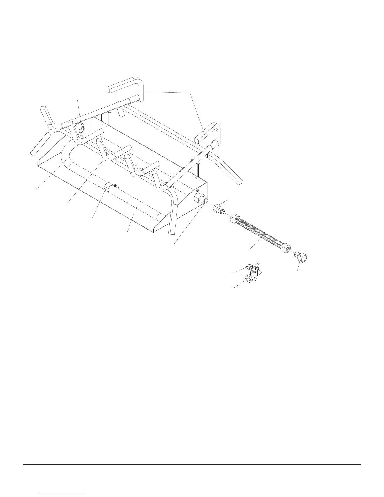
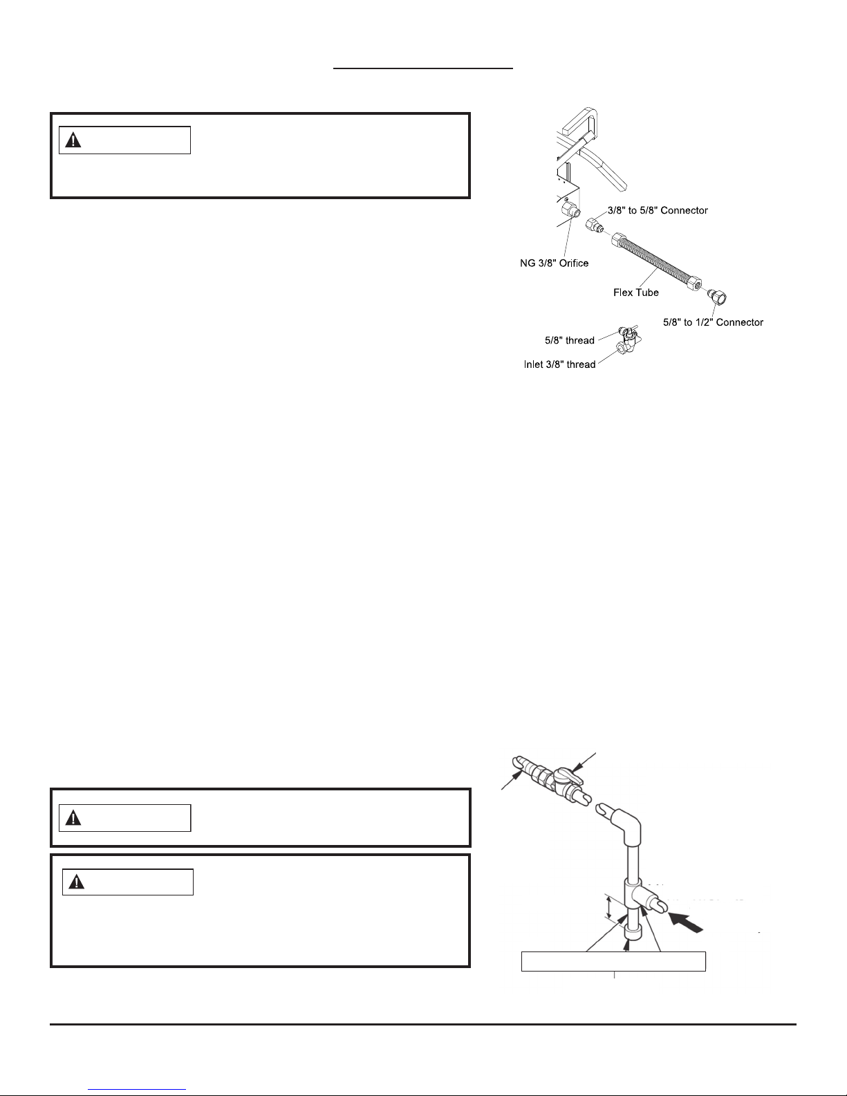
Cover Plate
Product Identication
Log Risers
Burner
Grate
Burner Clamp
Burner Pan
NG 3/8" Orifice
5/8" Thread
Inlet 3/8" Thread
3/8" to 5/8" Connector
Flex Tube
5/8" to 1/2" Connector
5
©2017 Pinnacle Climate Technologies
Vented Gas Log Appliance User’s Manual
General Preparation
CAUTION
LOCAL CODES
Install and use the appliance with care. Follow all local codes. In the absence of local codes, use the latest
edition of The National Fuel Gas Code, ANSI Z223.1, also known as NFPA 54*.
*Available from:
American National Standard Institute, Inc.
1430 Broadway
New York, NY 10018
The State of Massachusetts requires that the chimney ue damper be welded open or completely removed
if used with decorative gas log sets. This appliance must be installed by a licensed plumber or gas tter in
Massachusetts.
In the State of Massachusetts the gas cock must be a T-handle type. Massachusetts requires that a exible
appliance connector be three feet or less in length.
UNPACKING
Do not remove the metal data plates from the burner pan. The data plates contain
important product information.
National Fire Protection Association, Inc.
1 Batterymarch Park
Quincy, MA 02269-9101
Remove all hardware and materials from the product carton. Remove all protective packaging applied to the
materials and check for any shipping damage. If you notice any damage, contact Pinnacle Climate Technologies at (866) 676-1636.
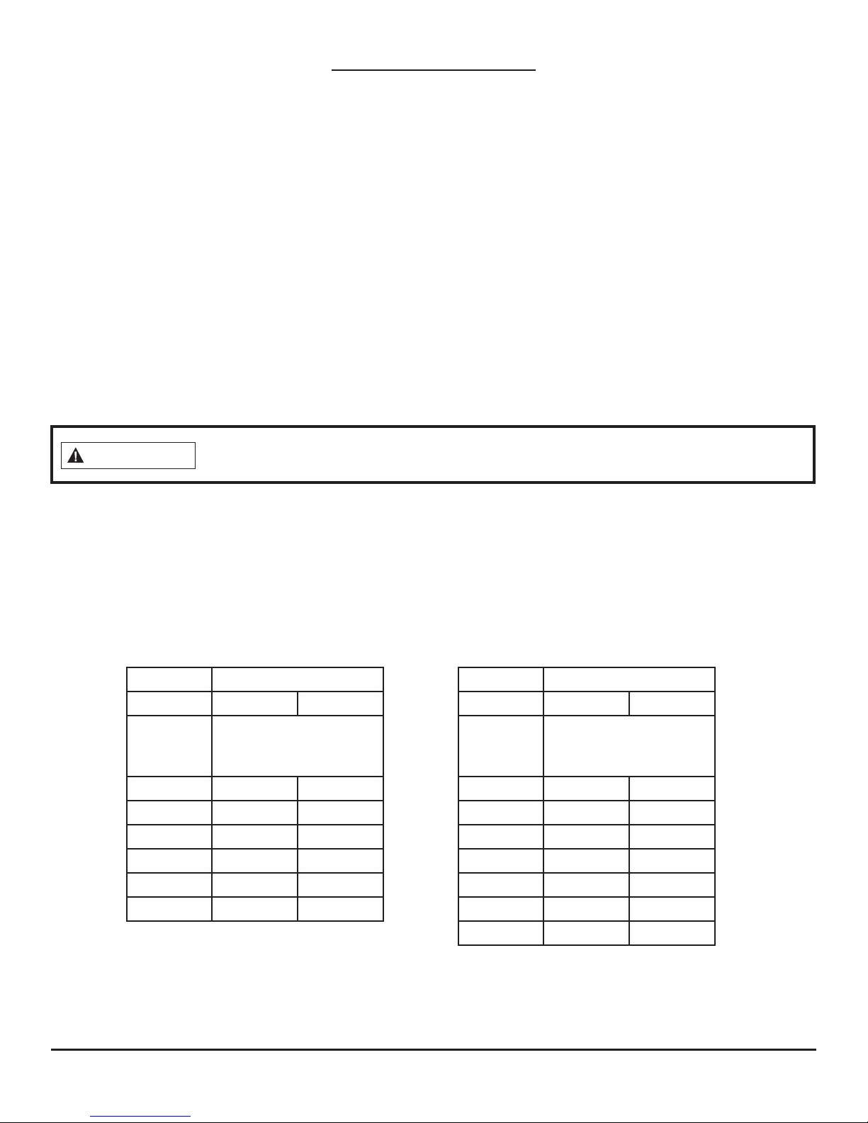
For Masonry-Built
Fireplaces Free Opening
Area of Chimney Damper
Log Set Size
18" 24"
Chimney
Height*
(ft)
Minimum Opening**
(sq. in.)
6 41.7 49.2
8 38.7 45.5
10 35.2 41.7
15
20
30
32.0 37.7
28.8 34.3
26.5 31.2
Fig. 1
Chimney
Height*
For Factory-Built
Fireplaces Free Opening
Area of Chimney Damper
Log Set Size
18" 24"
Minimum Opening**
(ft)
(sq. in.)
10 28.3 35.3
15 21.2 26.4
20 18.1 22.1
25
30
35
15.9 18.1
14.5 17.3
13.2 15.9
* Height is from hearth to hte top of the
chimney and the minimum height is 6 feet.
** Chart shows a minimum opening (sq. in.)
for a given height and input rate.
40
* Height is from hearth to the top of the
chimney and the minimum height is 10 feet.
** Chart shows a minimum opening (sq. in.)
for a given height and input rate.
12.6 15.2
6

©2017 Pinnacle Climate Technologies
Vented Gas Log Appliance User’s Manual
Preparing for Installation
WARNING
WARNING
WARNING
AIR FOR COMBUSTION AND VENTILATION
If the area in which the appliance will be operated does not meet the required volume
for indoor combustion air, combustion and ventilation air must be provided by one
of the methods described in the National Fuel Gas Code, ANSI Z223.1/NFPA 54, the International Fuel Gas
Code, or applicable local codes.
This appliance requires a reliable source of fresh air for adequate combustion and
ventilation. This is essential for the appliance to operate properly and for your own safety.
Before installing this appliance in a solid-fuel burning replace, a qualied chimney
cleaner must clean the chimney ue and rebox of ashes, loose paint, soot, and creosote.
Creosote ignites if heated to a high temperature. A dirty chimney ue may distribute soot
within the house. Make sure that the qualied chimney cleaner inspects the chimney ue for damage.
NOTICE: Installation, service, and repair of this appliance must be performed by a qualied installer, service
agency, company, or gas supplier experienced with this type of gas appliance. Only factory-authorized parts
may be used in accordance with the manufacturer’s instructions, and all codes and requirements of the authority having jurisdiction must be followed. Use of unauthorized parts or accessory items, or any alterations
to the kit, will void the manufacturer’s warranty. Using unauthorized parts or performing alterations may
also result in unsafe operating conditions.
Installation
CHECK GAS TYPE
Use only natural gas. If your gas supply is not natural gas, the On/O Safety Pilot Valve Kit (see ACCESSORIES,
page 16) must be installed. A gas supply shuto valve must be installed if the replace does not have one.
VENTING SPECIFICATIONS FOR INSTALLATION
Ensure the replace chimney ue and vent are drafting properly by doing the following:
1. Ignite a rolled newspaper or other paper on one end and place it at the inside front edge of the replace.
2. Watch the smoke and check that the vent is drawing it up the chimney.
3. If the smoke is not drawn up the chimney, extinguish the ame and remove obstructions in the chimney
until it vents properly.
The chimney ue must remain open a minimum of 3" at all times during the operation of this appliance.
Chimney dampers must be xed so that they maintain the minimum permanent vent opening at all times.
Installing a damper clamp to prevent the damper from accidentally closing is recommended (see page 8).
The minimum permanent opening (in square inches) is what must be provided by either the replace chimney or chimney damper to vent the ue gases. The minimum vent opening for dierent chimney heights can
be found on page 6 (Per 1.15.7.; ANSI 1.14.1B).
7
©2017 Pinnacle Climate Technologies
Vented Gas Log Appliance User’s Manual
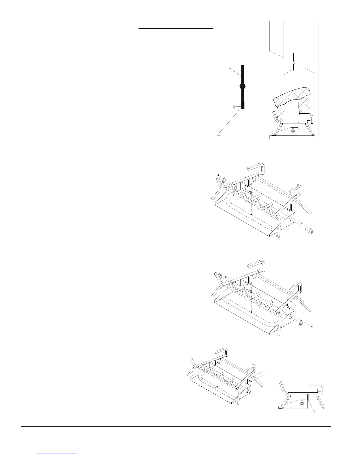
Installation (cont.)
Damper Clamp
Damper
PREPARE DAMPER
The chimney damper must be xed open such that it always
maintains the minimum permanent vent opening. To achieve
this, a.) install a screw or bolt in the edge of the damper to
prevent the damper from closing, b.) drill a hole or holes in
the damper blade, or c.) install the provided damper clamp on
the edge of the damper blade (see Figure 2).
NOTE: In the State of Massachusetts, the chimney damper
must be removed or welded in the fully open position.
HEARTH KIT ASSEMBLY
NOTE: The following instructions apply to dual ame
“U”-style burners. Ensure all pipe-threaded connections
are tight, and use thread compound to prevent leaks.
1. Determine from which side the gas line will be
entering into the replace.
• Gas line on the right side: This appliance is
manufactured with the gas inlet on the right side
of the burner pan. See INSTALLATION AND GAS
CONNECTION, page 9.
Fig. 2
Damper
“Opened Position”
Fig. 3
• Gas line on the left side: Continue with step 2.
2. Remove the cover plate on left side of the burner
pan by using a screwdriver (see Figure 3).
3. Unscrew the burner inlet tting from the burner
manifold (see Figure 3).
4. Place the burner manifold in the pan with the
threaded opening facing the opening on the left
side.
5. Using thread sealant (resistant to the action of
natural gas) on the larger end of the tting, screw
the burner inlet tting through hole and into burner
manifold. Tighten using a wrench (see Figure 4).
6. Using the provided burner clamp, screw, and nut,
attach the clamp to the pan. This holds the burner
manifold in place (see Figure 4).
7. Using the screws removed in step 2, install the cover
plate over the opening on the right side of the
burner pan (see Figure 4).
8. Attach the pan clamp brackets to the back of the
burner pan as shown (see Figure 5).
9. Position the grate into the V-grooves in the pan
clamp brackets (see Figure 5).
Fig. 4
Fig. 5
Pan clamp bracket
Screw
Pan clamp bracket
8
©2017 Pinnacle Climate Technologies
Vented Gas Log Appliance User’s Manual
Installation (cont.)
WARNING
WARNING
CAUTION
BEFORE INSTALLING THE APPLIANCE
Before installing the appliance, have the
fireplace and chimney professionally cleaned
to remove any soot, creosote, ashes, or other
obstructions. Perform this cleaning annually after installation.
• Turn o the gas supply to the replace or rebox.
• Clean the replace oor and chimney, seal any ash, and
clean out the doors to protect from any down drafts.
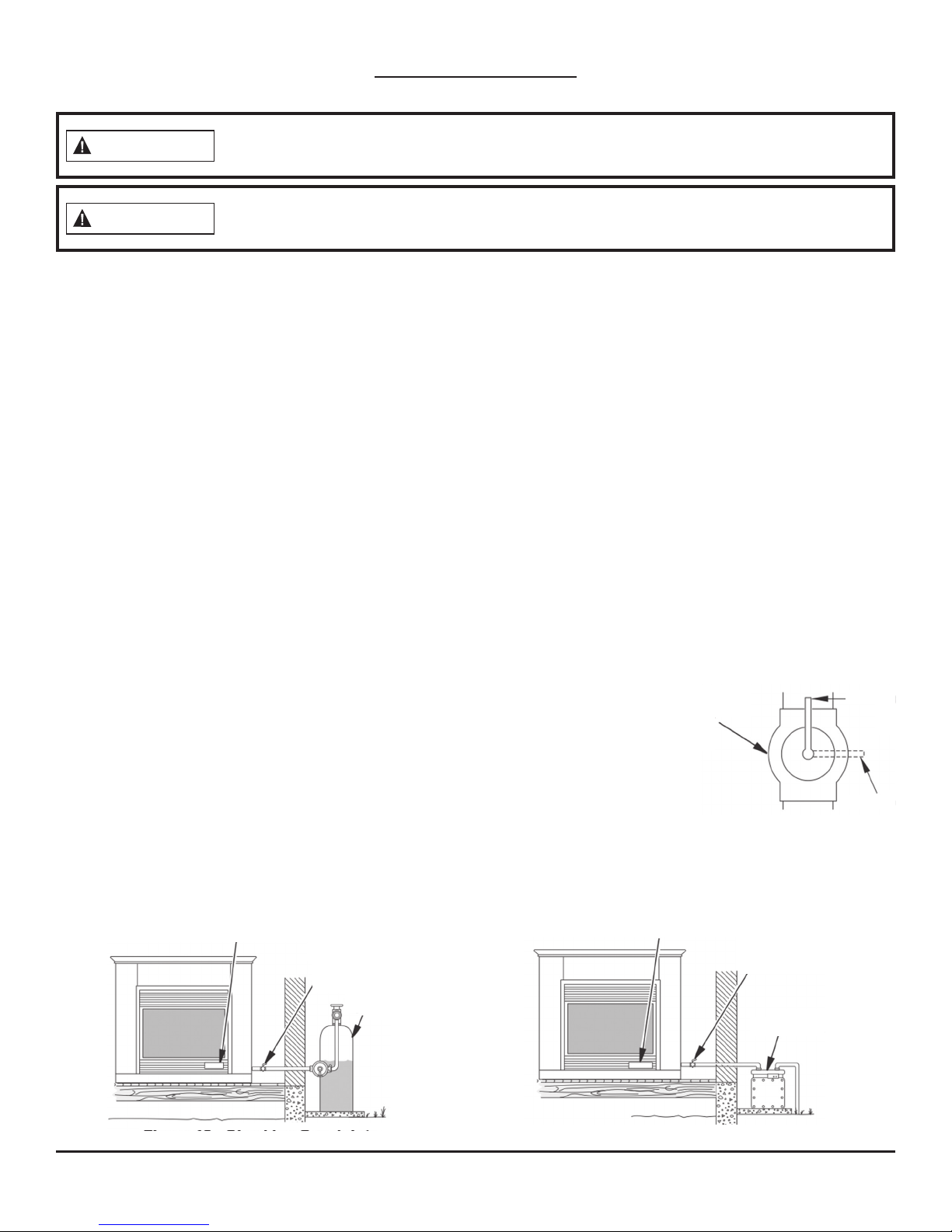
INSTALLATION AND GAS CONNECTION* (See Fig. 6 & 7)
1. Place the burner pan assembly in the center of the replace
oor. The front of the pan must face forward.
2. Install the 3/8" orice tting onto the burner inlet tting using
thread sealant on male threads of the burner inlet tting.
3. If the gas supply has an equipment shuto valve within
reach of lighting the log set, then thread the 1/2" connector
to the shuto valve. Use thread sealant.
4. If the gas supply does not have an equipment shuto valve
within reach, a manual gas valve is provided. Connect the
manual gas valve to gas supply pipe. Use thread sealant.
5. Attach the gas ex tube to the gas supply. Shape the tube
to attach to the orice tting.
CONNECTION TO GAS SUPPLY
Installation Items Needed:
• piping (check local codes)
• sealant (resistant to natural gas)
• equipment shuto valve
• test gauge connection
Installation must include an equipment shuto valve, union,
and plugged 1/8" NPT tap. Locate the NPT tap within reach
for test gauge hook up. The NPT tap must be upstream from
the appliance (see Figure 7).
A qualified service person must connect the
appliance to gas supply. Follow all local codes.
Only use a new black iron or steel pipe.
Internally-tinned copper tubing may be
used in certain areas. Check local codes. To allow proper gas
volume to the appliance, use a pipe of 1/2" diameter or greater.
Loss of pressure occurs if the pipe is too small.
* In compliance with ANS Z21.60•CSA2.26 and National Fuel Gas Code, Section 6.
• sediment trap
• tee joint
• pipe wrench
• adjustable (crescent)
wrench or pliers
Fig. 6
IMPORTANT: Install the equipment shuto valve
in an accessible location. The equipment shuto
valve is used for turning on or shutting o the
gas to the appliance.
Lightly apply pipe joint sealant to the male
threads. This prevents excess sealant from going
into the pipe. A clogged burner injector may
result from excess sealant in the pipe.
Install the sediment trap in the supply line (see
Fig. 7). Locate the sediment trap so it can easily
be cleaned and where trapped material is unlikely to freeze. A sediment trap traps moisture and
contaminants, keeping them from going into the
appliance controls. The appliance may not operate correctly if the sediment trap is not installed
or is installed incorrectly.
Fig. 7
Equipment Shuto Valve With
1/8" NPT Tap
Propane/LP
Approved
Flexible
Gas Line
or 1/2"
Black Pipe
3" Minimum
Pipe Nipple Cap Tee Joint
Sediment Trap
From External
Regulator (11"
W.C. to 14" W.C
Pressure)
Natural
From Gas Meter
(7" W.C.** to
(5.5''
10.5" W.C.
7''
Pressure)
9
©2017 Pinnacle Climate Technologies
Vented Gas Log Appliance User’s Manual
Installation (cont.)
WARNING
WARNING
CHECKING GAS CONNECTIONS
After installing or servicing the appliance, test all gas piping and connections for leaks.
Immediately correct all leaks.
Never use an open ame to check for a leak. Apply a mixture of liquid soap and water to
all joints. There may be a leak if bubbles form. Immediately correct all leaks.
Pressure Testing Gas Supply Piping System
Test Pressures in Excess Of 1/2 PSIG (3.5 kPa):
1. Disconnect the appliance, including the main gas valve (control valve) and equipment shuto valve,
from the gas supply piping system. Pressures greater than 1/2 PSIG will damage the regulator.
2. Cap o the open end of the gas pipe where the equipment shuto valve was connected.
3. Open the gas supply tank valve or use compressed air to pressurize the supply piping system.
4. Check all joints of the gas supply piping system. Use a mixture of liquid soap and water in the gas joints
to check for leaks—bubbles may indicate a leak.
5. Immediately correct all leaks.
6. Reconnect the appliance and equipment shuto valve to gas supply. Check reconnected ttings for leaks.
Test Pressures Equal To or Less Than 1/2 PSIG (3.5 kPa):
1. Close equipment shuto valve (see Fig. 8).
2. Open the gas supply tank valve or use compressed air to pressurize the supply piping system.
3. Check all joints from the gas meter to equipment shuto valve (see Fig. 9.1 & 9.2).
4. Use a mixture of liquid soap and water in the gas joints to check for leaks—bubbles may indicate a leak.
5. Immediately correct all leaks.
Pressure Testing Appliance Gas Connections:
1. Open the equipment shuto valve (see Fig. 8).
2. Open the gas supply tank valve.
3. Ensure the control knob of the appliance is in the OFF position.
4. Check all joints from the equipment shuto valve to the control valve
(see Fig. 9.1 & 9.2). Use a mixture of liquid soap and water in the gas
joints to check for leaks—bubbles may indicate a leak.
5. Light the appliance (see OPERATION, page 13). Check all other internal
joints for leaks.
6. Turn o the appliance (see TO TURN OFF GAS TO THE APPLIANCE, page 13).
Equipment
Shuto
Valve
Fig. 8
Open
Closed
Fig. 9.1—Checking Gas Joints (Propane/LP Only)
Gas Control Valve
Equipment
Shuto
Valve
Propane/
LP Supply
Tank
Fig. 9.2—Checking Gas Joints (Natural Gas Only)
Gas Control Valve
10
Equipment
Shuto Valve
Gas Meter

©2017 Pinnacle Climate Technologies
Vented Gas Log Appliance User’s Manual
Installation (cont.)
WARNING
ADDING PAN MATERIAL
Apply loose material (embers and lava rock/cinders) per the instruction manual. Never
apply extra material not supplied with the appliance. Previously applied material
(embers) must be removed prior to reapplication.
1. Spread ash bed material (Vermiculite) evenly across the burner pan to the top. It is ne to cover the connecting hardware and the burner pan, but DO NOT cover the gas valve.
2. Evenly cover the Vermiculite with the Glowing Embers, using 1/2" size ember ber pieces.
3. Place the Lava Rock around the burner assembly. DO NOT place it inside of the appliance or on the logs.
Only place the Lave Rock on the replace oor.
11
©2017 Pinnacle Climate Technologies
Vented Gas Log Appliance User’s Manual
Log Assembly
WARNING
CAUTION
Positioning the parts not in accordance with these illustrations or using unapproved
parts may result in property damage or personal injury.
Check to ensure that no yellow ame comes in contact with any log, both after installation
and periodically afterwards. Set the appliance to HIGH and check if yellow ames come
into contact with any log. If so, reposition the logs as indicated in the below illustrations. Yellow ames coming
into contact with logs creates soot.
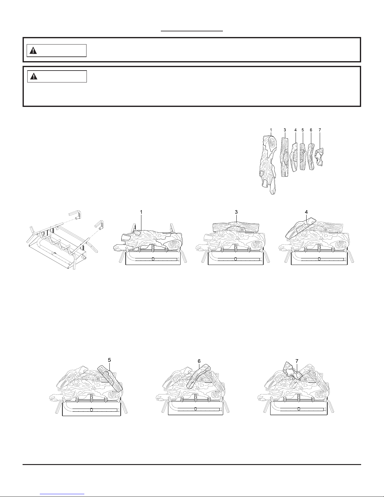
Install the logs exactly as indicated (see Fig. 10–16). Do
not modify the logs, and use only logs supplied with the
appliance. The logs are numbered and correspond to the
numbers listed below.
NOTE: The instructions below are designed to reduce the
amount of sooting created by the appliance.
NOTE: This log set does not contain a log #2.
Fig. 10 Fig. 11 Fig. 12 Fig. 13
1. After adding pan
material (see page 11),
slide both risers onto the
back of the grate. Ensure
the back of the grate is
ush with the back of
the riser.
2. Place log #1 on
the top of the front
grate and ensure
the log is centered.
3. Place log #3
on the top of the
risers. Ensure the
log is centered.
Number of Logs: 6
4. Place log #4 so it
rests on the top left
of logs #1 and #3.
Fig. 14 Fig. 15 Fig. 16
5. Place log #5 so it
rests on the top right
of logs #1 and #3.
6. Place log #6 so
it rests on the top
of logs #1 and #5.
12
6. Place log #7 so it
rests on the top of
logs #4 and #6.
 Loading...