

Remington REM-B200LT-F, REM-B100LT-F, REM-B300NT-F, REM-B300LT-F, REM-B100NT-F User's Manual And Operating Instructions
...
VENT-FREE
!
WARNING
GAS HEATER
User’s Manual and
Operating Instructions
Models:
REM-B300LT-F / REM-B200LT-F / REM-B100LT-F /
REM-B300NT-F / REM-B200NT-F / REM-B100NT-F
This appliance
is equipped
for natural or
propane gas. Field
conversion is not
permitted.
CAUTION —FOR YOUR SAFETY
WARNING: If the information in this manual is not followed exactly, a re or
explosion may result causing property damage, personal injury, or loss of life.
Models:
REM-R280LT-F / REM-R300NT-F /
REM-R150LM-F / REM-R180NM-F
ANS Z21.11.22013
• Do not store or use gasoline or other ammable vapors and liquids in the vicinity of this or any
other appliance.
• WHAT TO DO IF YOU SMELL GAS:
• Do not try to light any appliance.
• Do not touch any electrical switch; do not use any phone in your building.
• Immediately call your gas supplier from a neighbor’s phone. Follow the gas supplier’s instructions.
• If you cannot reach your gas supplier, call the re department.
• Installation and service must be performed by a qualied installer, service agency, or the gas supplier.
This is an unvented gas-red heater. It uses air (ox ygen) from the room in which it is installed. Provisions
for adequate combustion and ventilation air must be provided. Refer to the AIR FOR COMBUSTION
AND VENTILATION section on page 8 of this manual.
This appliance may be installed in an aftermarket, permanently located, manufactured (mobile)
home, where not prohibited by local codes. This appliance is only for use with the type gas indicated
on the rating plate. This appliance is not convertible for use with other gases.
INSTALLER: Leave this manual with the appliance.
CONSUMER: Retain this manual for future reference.
Fax: 320-251-2922 • Web: www.remingtonheater.com • Email: info@pinnacleclimate.com
1 Industrial Blvd #101, Sauk Rapids, MN 56379 USA • Toll Free (866) 676-1636
© 2017 Pinnacle Climate Technologies, Inc. REWC-420
©2017 Pinnacle Climate Technologies
Vent-Free Gas Heater User’s Manual
Table of Contents
WARNING
Specications ........................................................................................................................................................................................2
Safety Information .............................................................................................................................................................................. 3
Product Identication ........................................................................................................................................................................ 6
General Preparation ...........................................................................................................................................................................7
Preparing for Installation .................................................................................................................................................................. 8
Installation ............................................................................................................................................................................................11
Operation ..............................................................................................................................................................................................20
Care and Maintenance .....................................................................................................................................................................24
Troubleshooting Guide .................................................................................................................................................................... 26
Parts List ................................................................................................................................................................................................. 29
Limited Warranty ................................................................................................................................................................................31
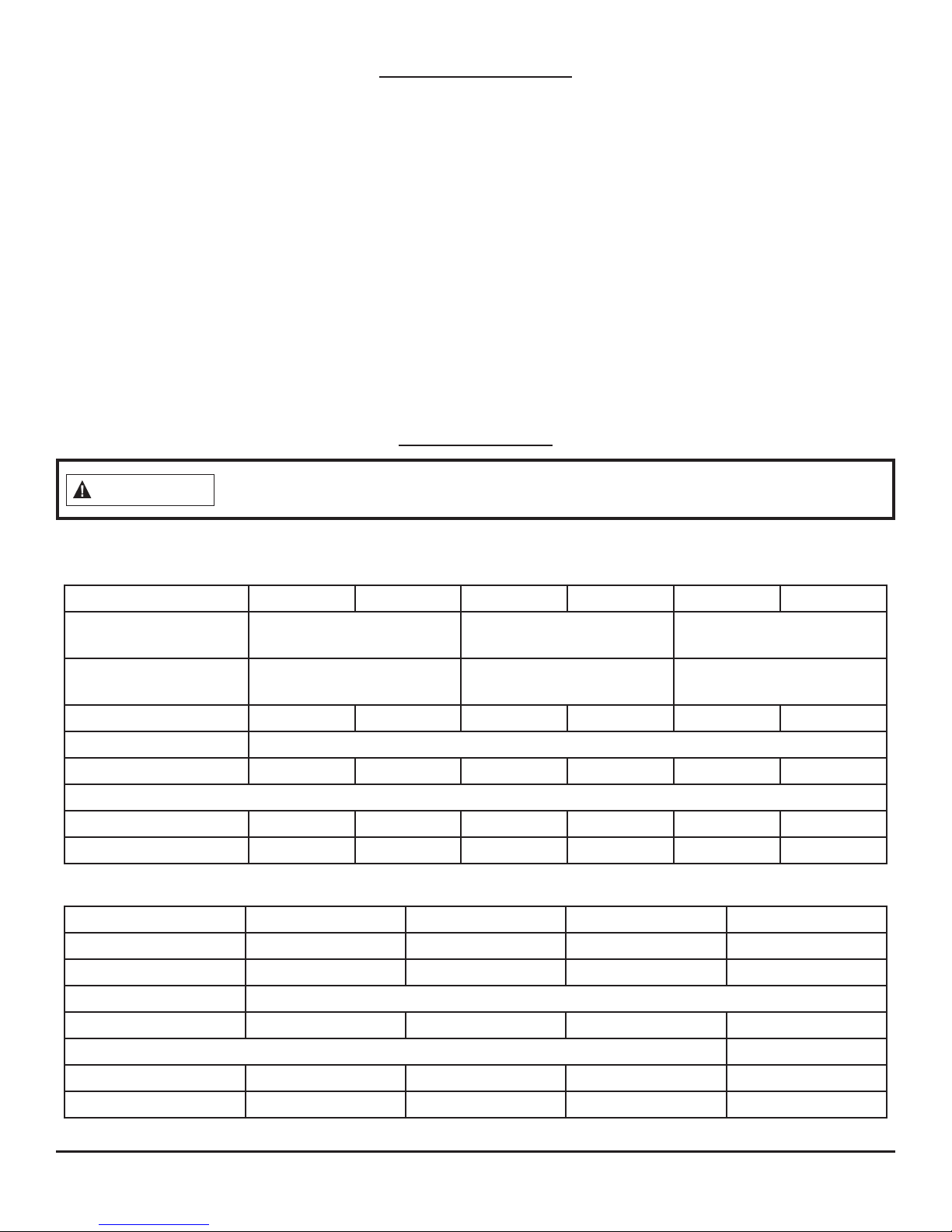
Specications
Read this entire manual and all operating instructions before operating this heater.
IMPORTANT: Read all instructions and warnings carefully before starting installation. Failure to follow
these instructions may result in possible injury to persons or a re hazard and will void the warranty.
Model #
Max. Input Rating
(BTU/Hr)
Min. Input Rating
(BTU/Hr) (Min.)
Gas Type LP/Propane Natural LP/Propane Natural LP/Propane Natural
Ignition Type Piezo
Manifold Pressure 9 in. W.C. 4 in. W.C. 9 in. W.C. 4 in. W.C. 9 in. W.C. 4 in. W.C.
Inlet Gas Pressure
Maximum 14 in. W.C. 7 in. W.C. 14 in. W.C. 7 in. W.C. 14 in. W.C. 7 in. W.C.
Minimum* 11 in. W.C. 5 in. W.C. 11 in. W.C. 5 in. W.C. 11 in. W.C. 5 in. W.C.
*For Purpose of Input Adjustment
Model # REM-R150LM-F REM-R180NM-F REM-R280LT-F REM-R300NT-F
Input Rating (BTU/Hr) 15,000 18,000 28,000 29,500
Gas Type LP/Propane Natural LP/Propane Natural
REM-B100LT-F REM-B100NT-F REM-B200LT-F REM-B200NT-F REM-B300LT-F REM-B300NT-F
10,000 20,000 30,000
6,750 13,000 19,750
Ignition Type Piezo
Manifold Pressure 10 in. W.C. 6 in. W.C. 10 in. W.C. 6 in. W.C.
Inlet Gas Pressure
Maximum
Minimum* 11 in. W.C. 7 in. W.C. 11 in. W.C. 7 in. W.C.
*For Purpose of Input Adjustment
14 in. W.C. 11 in. W.C. 14 in. W.C. 11 in. W.C.
2
©2017 Pinnacle Climate Technologies
Vent-Free Gas Heater User’s Manual
Safety Information
WARNING
IMPORTANT: Read this owner’s manual carefully and completely before trying to assemble, operate, or
service this heater. Improper use of this heater can cause serious injury or death from burns, re, explosion,
electrical shock, and carbon monoxide poisoning.
Only a qualied installer, service agent, or local gas supplier may install and service this product.
CARBON MONOXIDE POISONING: Early signs of carbon monoxide poisoning resemble
the u with headaches, dizziness, or nausea. If you have these signs, the heater may
not be working properly. Get fresh air immediately, and have the heater serviced. Some people are more
aected by carbon monoxide than others: pregnant women, people with heart or lung disease, people
who are anemic, those under the inuence of alcohol, and those living in high altitudes.
NATURAL AND PROPANE/LP GAS: Natural and propane/LP gases are odorless. An odor-making agent is
added to the gas. The odor helps you detect a gas leak. However, the odor added to the gas can fade. Gas
may be present even though no odor exists. Make certain you read and understand all warnings. Keep this
manual for reference. It is your guide to operating this heater safely.
WARNING:
• Due to high temperatures, the heater should be located out of trac and away from furniture and draperies.
• The heater becomes very hot when operating. Children and adults should be alerted to the hazard of
high surface temperature and should stay away to avoid burns or clothing ignition. The heater will remain hot for a time after shuto.
• Allow surfaces to cool before touching.
• Young children should be carefully supervised when they are in the same room with the appliance.
• Do not place clothing or other ammable material on or near the heater. Never place any objects in
the heater.
• Installation and repair should be done by a qualied service person. The heater should be inspected before use and at least annually by a professional service person. More frequent cleaning may be required
due to excessive lint from carpeting, bedding material, etc. It is imperative that control compartments,
burners, and circulating air passageways of the heater be kept clean.
• Any safety screen or guard removed for servicing an appliance must be replaced prior to operating
the heater.
• Any change to this heater or its controls can be dangerous.
• Do not use any accessories not approved for use with this heater.
• Keep the heater area clear and free from combustible materials, gasoline, and other ammable vapors
and liquids.
• This appliance is intended for supplemental heating.
CALIFORNIA PROPOSITION 65: Fuels used in gas or oil red heaters and the products of combustion
of such fuels contain chemicals known to the state of California to cause cancer, birth defects, or other
reproductive harm. This product contains chemicals, including lead and lead compounds, known to the
state of California to cause cancer, birth defects, or other reproductive harm. Wash hands after handling.
3

©2017 Pinnacle Climate Technologies
Vent-Free Gas Heater User’s Manual
Safety Information (cont.)
WARNING:
• This heater must only be used with the type of gas indicated on the rating label. This heater is not
convertible for use with other gases.
• Do not place propane/LP supply tank(s) inside any structure. Place propane/LP supply tank(s) outdoors.
• If you smell gas, do the following:
• Shut o the gas supply;
• Do not try to light any appliance;
• Do not touch any electrical switch, and do not use any phone in your building;
• Immediately call your gas supplier from a neighbor’s phone. Follow the gas supplier’s instructions. If
you cannot reach your gas supplier, contact the re department.
• Before using furniture polish, wax, carpet cleaner, or similar products, turn the heater o. If heated, the
vapors from these products may create a white powder residue within the burner box or on adjacent
walls or furniture.
• This heater must never be installed in a bedroom or bathroom.
• This heater needs fresh air ventilation to run properly and safely. This heater has an Oxygen Depletion
Sensing (ODS) safety shuto system. The ODS shuts down the heater if not enough fresh air is available.
See AIR FOR COMBUSTION AND VENTILATION, page 8. If the heater keeps shutting o, see the
TROUBLESHOOTING GUIDE, page 26.
• Do not run the heater:
• Where ammable liquids or vapors are used or stored;
• Under dusty conditions.
• Do not use this heater to cook food or burn anything.
• Do not use the heater if any part has been under water. Before use, call a qualied service technician to
inspect the heater and replace any part of the control system and/or gas control that has been under
water.
• Turn o and let the heater cool before servicing. Only a qualied service person should service and repair
the heater.
• Operating the heater above elevations of 4,500 feet may cause pilot outage.
• To prevent performance problems, do not use propane/LP fuel tank of less than 100 lb. capacity.
• Provide adequate clearances around air openings.
4
©2017 Pinnacle Climate Technologies
Vent-Free Gas Heater User’s Manual
WARNING
Safety Information (cont.)
QUALIFIED INSTALLING AGENCY: Only a qualied agency should install and replace gas piping, gas
utilization equipment, or accessories, and/or repair and service such equipment. “Qualied agency” means
any entity that either in person or through a representative is engaged in and is responsible for:
• Installing, testing, or replacing gas piping; or
• Connecting, installing, testing, repairing, or servicing equipment; is experienced in such work; is familiar with
all precautions required; and has complied with all the requirements of the authority having jurisdiction.
Failure to position the parts in accordance with these diagrams or failure to use only parts
specically approved with this heater may result in property damage or personal injury.
Before beginning assembly or operation of this heater, ensure all parts are present. Check the parts against
the package contents list. If any part is missing or damaged, do not attempt to assemble, install, or operate
the heater. Contact customer service for replacement parts.
Estimated Assembly Time: 1 to 2 hours
Tools Required for Assembly (not included, unless otherwise stated):
Before installing the heater, ensure you have the following:
• Hardware package (included)
• Approved exible gas hose if allowed by local codes
• Sealant (resistant to natural or propane/LP gas)
• Electric drill with 3/16" drill bit
• Phillips screwdriver
• External regulator (supplied by installer if required)
• Piping (check local codes)
• Equipment shuto valve
• Test gauge connection
• Sediment trap
• Tee joint
• Pipe wrench
• 3/8" NPT to 3/8" are tting
UNPACKING
1. Remove heater and base from the carton.
2. Remove all protective packaging used on the heater.
3. Inspect the items for shipping damage. If you notice any damage, contact the dealer where the heater
was purchased.
5

©2017 Pinnacle Climate Technologies
Vent-Free Gas Heater User’s Manual
Product Identication
Models:
REM-B300LT-F / REM-B200LT-F / REM-B100LT-F /
REM-B300NT-F / REM-B200NT-F / REM-B100NT-F
Models:
REM-R280LT-F / REM-R300NT-F /
REM-R150LM-F / REM-R180NM-F
SAFETY PILOT
This heater has a pilot with an Oxygen Depletion Sensing (ODS) safety shuto system. The ODS/pilot shuts
o the heater if there is not enough fresh air and cuts o the main burner gas in the event of ame out.
THERMOSTAT HEAT CONTROL
The control automatically cycles the burner on and o to maintain a desired room temperature (see page
21). When used as a vented decorative appliance, use of the thermostat function is prohibited. Operate
manually only.
LEG KIT (Select models)
Two (2) support legs and four (4) support leg screws are included for oor mounting the heater. See page 14.
NOTE: This is an optional accessory and is not required for operation of the heater.
FAN KIT (Select models)
The fan kit helps to distribute the warmed air into the space more rapidly.
NOTE: This is an optional accessory and is not required for operation of the heater.
6

©2017 Pinnacle Climate Technologies
Vent-Free Gas Heater User’s Manual
General Preparation
LOCAL CODES
Install and use the heater with care. Follow all local codes. The installation must conform with local codes or,
In the absence of local codes, with the latest edition of The National Fuel Gas Code, ANS Z223.1/NFPA 54*.
*Available from:
American National Standard Institute, Inc.
1430 Broadway
New York, NY 10018
This heater is designed for vent-free operation. State and local codes in some areas prohibit the use of ventfree heaters.
State of Massachusetts: The installation must be made by a licensed plumber or gas tter in the
Commonwealth of Massachusetts. Sellers of unvented propane or natural gas-red supplemental room
heaters shall provide to each purchaser a copy of 527 CMR 30 upon sale of the unit.
In the State of Massachusetts, unvented propane or natural gas-red space heaters are prohibited in
bedrooms and bathrooms.
National Fire Protection Association, Inc.
1 Batterymarch Park
Quincy, MA 02269-9101
The installation of appliances designed for manufactured home (U.S. only) or mobile home installation
must conform with the Standard CAN/CSA Z240 MH, Mobile Housing, in Canada, or with the Manufactured
Home Construction and Safety Standard, Title 24 CFR, Part 3280, in the United States, or when such a
standard is not applicable, ANS/NCSBCS A225.1/NFPA 501A, Manufactured Home Installations Standard.
7

©2017 Pinnacle Climate Technologies
Vent-Free Gas Heater User’s Manual
Preparing for Installation
WATER VAPOR IS A BY-PRODUCT OF UNVENTED ROOM HEATERS
Gas combustion creates water vapor as a by-product. Unvented room heaters create about one (1) ounce (30
ml) of water for every 1,000 BTUs (0.3 kW) of gas input per hour. An unvented room heater is recommended
as a supplemental heat source for a single room rather than as a primary heat source for an entire house. The
water vapor does not typically create a problem. In most cases, the water vapor enhances the low humidity
conditions that are typical of cold weather.
Keep these points in mind so that the water vapor does not create a problem:
• The heater must be the proper size for the application. Provide adequate combustion air and circulation air.
• In humid environments, use a dehumidier to help lower the amount of water vapor in the air.
• Do not use an unvented room heater as your primary heat source.
AIR FOR COMBUSTION AND VENTILATION
This heater shall not be installed in a room or space unless the required volume of indoor combustion air is
provided by the method described in the National Fuel Gas Code, ANS Z223.1/NFPA 54, the International Fuel
Gas Code, or applicable local codes.
PRODUCING ADEQUATE VENTILATION
Spaces in homes can be divided into these ventilation classications:
• Unusually Tight Construction
• Unconned Space
• Conned Space
The information on pages 8–10 will help you classify your space and provide adequate ventilation.
Conned and Unconned Space:
A conned space has a volume less than 50 cu. ft. per 1,000 BTU/hr (4.8 m
3
per kW) of the total input rating
of all appliances installed in that space. An unconned space has a volume not less than 50 cu. ft. per 1,000
BTU/hr (4.8 m
3
per kW) of the total input rating of all appliances installed in that space. Rooms that are
directly connected to the space in which the appliances are installed*, through openings that do not have
doors, are considered a part of the unconned space.
Do not install this heater in a conned space or unusually tight construction unless you provide provisions
for adequate combustion and ventilation air.
*Adjoining rooms are directly connected only if there are doorless passageways or ventilation grills between them.
Unusually Tight Construction:
Doors and windows may leak air that provides enough fresh air for combustion and ventilation. However,
you must provide additional fresh air in buildings of unusually tight construction. Unusually tight
construction is dened as construction that meets the following criteria:
A. Walls and ceilings exposed to the outside atmosphere have a continuous water vapor retarder with a
rating of one perm (6x10-11kg per pa-sec-m2) or less with openings that are gasketed or sealed.
B. Doors and windows that can be opened have weather stripping.
C. Caulking or sealants are applied to areas such as joints around window and door frames; between sole
plates and oors; between wall-ceiling joints; between wall panels; at penetrations for plumbing, electri-
cal, and gas lines; and at other openings.
If your residence meets all the above criteria, additional fresh air must be provided. See VENTILATION AIR
FROM OUTDOORS on page 10 for more information. If your residence does not meet those three criteria,
continue to DETERMINING FRESHAIR FLOW FOR THE HEATER LOCATION.
8

©2017 Pinnacle Climate Technologies
Vent-Free Gas Heater User’s Manual
Preparing for Installation (cont.)
DETERMINING FRESH-AIR FLOW FOR THE HEATER LOCATION
Determining if You Have a Conned or Unconned Space:
Use the below information to determine if you have a conned or unconned space. Your space includes the
room in which you will install the heater plus any other rooms that are directly connected and have doorless
passageways or ventilation grills between the rooms.
1. Determine the volume of the space. Length × Width × Height = cu. ft. (volume of space)
• Example: 20 ft. (length) × 16 ft. (width) × 8 ft. (ceiling height) = 2560 cu. ft. (volume of space)
If additional ventilation to adjoining room(s) is supplied with grills or openings, add the volume of these
rooms to the total volume of your space.
2. Divide the space’s volume by 50 cu. ft. to determine the maximum BTU/hr the space can support.
_______ (volume of space) ÷ 50 cu. ft. = (maximum BTU/hr the space can support)
• Example: 2560 cu. ft. (volume of space) ÷ 50 cu. ft. = 51.2 or 51,200 (maximum BTU/hr the space can support)
3. Add the BTU/hr of all fuel burning appliances in the space:
Example:
Gas heater __________BTU/hr Gas water heater 40,000 BTU/hr
Other gas appliances*+ ____BTU/hr Vent-free heater + 30,000 BTU/hr
Total = ____BTU/hr Total = 70,000 BTU/hr
*Do not include direct-vent gas appliances. Direct-vent appliances draw combustion air from outdoors
and vent to the outdoors.
4. Compare the maximum BTU/hr the space can support with the actual amount of BTU/hr used:
_______ BTU/hr (maximum the space can support)
_______ BTU/hr (actual amount of BTU/hr used).
• Example : 51,200 BTU/hr (maximum the space can support) 70,000 BTU/hr (actual amount of BTU/hr used)
The space in the above example is a conned space because the actual BTU/hr used is more than the
maximum BTU/hr the space can support. You must provide additional fresh air. Your options are as follows:
A. Add the space of an adjoining room and rework the above information. If the extra space creates an
unconned space, remove the door to the adjoining room or add ventilation grills between rooms. See
VENTILATION AIR FROM INSIDE A BUILDING, page 10.
B. Vent the room directly to the outdoors. See VENTILATION AIR FROM OUTDOORS, page 10.
C. Install a heater that uses less BTUs/hr if the lower BTUs/hr creates an unconned space. If the actual BTU/
hr used is less than the maximum BTU/hr the space can support, the space is an unconned space. In this
case, no additional fresh air ventilation is needed.
9
©2017 Pinnacle Climate Technologies
Vent-Free Gas Heater User’s Manual
Preparing for Installation (cont.)
WARNING
12 in.
Ventilation Grills
Into adjoining Room
Option 2
Or
Remove
Door
Into
Adjoining
Room
Option 3
Ventilation
Grills
Into Adjoining
Room
Option 1
If the area in where the heater operates does not meet the required volume for
indoor combustion air, you must provide combustion and ventilation air by one of the
methods described in the NATIONAL FUEL GAS CODE, ANS Z223.1/NFPA 54, the INTERNATIONAL FUEL GAS
CODE, or applicable local codes.
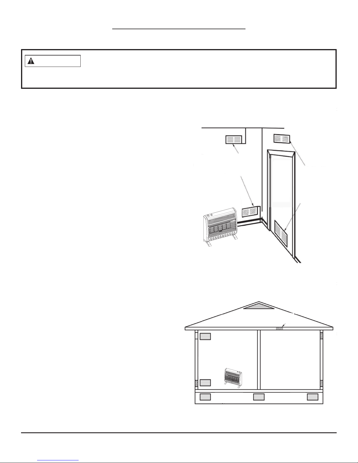
VENTILATION AIR FROM INSIDE A BUILDING
Fresh air comes from a connected unconned space.
You must provide two permanent openings when
ventilating to a connected unconned space, one of
which that’s within 12" of the wall that connects the
two spaces (see options 1 and 2, Fig. 1). You may also
remove the door into the adjoining room (see option 3,
Fig. 1). Follow the National Fuel Gas Code NFPA 54/ANS
Z223.1 for the required size of ventilation grills or ducts.
VENTILATION AIR FROM OUTDOORS
Extra fresh air is provided via ventilation grills or
ducts. You must provide two permanent openings:
one within 12" of the ceiling and one within 12" of the
oor (see Fig. 2). They must connect directly to the
outdoors or spaces that open to the outdoors. Such
spaces may include attics or crawl spaces. Follow the
National Fuel Gas Code NFPA 54/ANS Z223.1 for the
required size of ventilation grills or ducts.
Fig. 1—Ventilation Air from Inside a Building
12 in.
Ventilation Grills
Into adjoining Room
Option 2
Or
Remove
Door
Into
Adjoining
Room
Option 3
Ventilation
Grills
Into Adjoining
Room
Option 1
Fig. 2—Ventilation Air from Outdoors
IMPORTANT: Do not provide openings for inlet or
outlet air into an attic if the attic has a thermostatcontrolled power vent. The power vent will be
activated by heated air that enters the attic. You must
add the space of the connected unconned space
and rework the information on page 9. The combined
spaces must have enough fresh air to supply all
appliances in both spaces.
Ventilated
Attic
To
Attic
To
Crawl
Space
Ventilated
Crawl Space
Outlet
Air
Outlet
Air
Inlet
Air
Inlet Air
10

©2017 Pinnacle Climate Technologies
Vent-Free Gas Heater User’s Manual
Installation
WARNING
WARNING
CAUTION
NOTICE: This heater is intended to be used as a supplemental heating source. Use this heater along with
your primary heating system. This heater must not be used as a primary heat source. If you have a central
heating system, you may run that system’s circulating blower while using this heater. This helps to circulate
the heat around your house.
A qualied technician must install the heater. Follow all local codes.
Never install the heater in a bedroom or bathroom; in a recreational vehicle; where
curtains, furniture, clothing, or other ammable objects are less than 36" from the
front, top, or sides of the heater; in high trac areas; or in windy or drafty areas.
This heater creates warm air currents. These currents move heat to wall surfaces that
are next to the heater. Installing the heater next to vinyl or cloth wall coverings, or
operating the appliance where impurities in the air exist (tobacco smoke, aromatic candles, cleaning uids,
oil or kerosene lamps, etc.), may cause walls to discolor.
IMPORTANT: Vent-free heaters add moisture to the air, which is benecial. However, if this heater is installed
in areas without adequate ventilation, mildew may form from too much moisture in the air. See AIR FOR
COMBUSTION AND VENTILATION, pages 8 through 10.
CHECK GAS TYPE: Be sure your gas supply is right for your heater. If the supply is not correct, do not install
the heater. Contact the place where this heater was purchased for a heater appropriate for your gas supply.
NOTICE: State or local codes may only allow operation of this appliance in a vented conguration. Check
your state or local codes.
11
©2017 Pinnacle Climate Technologies
Vent-Free Gas Heater User’s Manual
Installation (cont.)
CAUTION
WARNING
HEATER CLEARANCES
For convenience and eciency, install the heater with these points in mind:
• Provide easy access for operation, inspection and service.
• Install the heater in the coldest part of the room.
If this heater is installed directly on carpeting, tile, or other combustible material, other than wood ooring,
the heater must be installed on a metal or wood panel that extends the heater’s full width and depth.
If you install the heater in a home garage, a.) ensure the heater pilot and burner are at
least 18" above the oor and, b.) locate the heater where moving vehicles will not hit it.
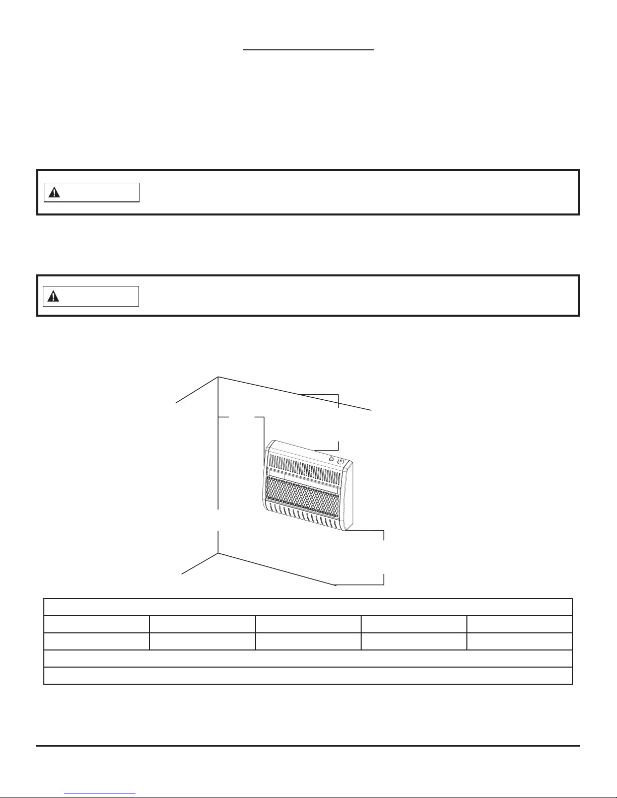
Clearances to Combustibles:
Carefully follow the instructions below. This heater can be mounted on the wall or on the oor using
the support legs (select models).
Maintain the minimum clearances shown in (see Fig. 3). If you can, provide greater
clearances from oor, ceiling, and joining wall.
Fig. 3—Mouting Clearances as Viewed from the Front of
the Heater (Inches)
CEILING
8"
Minimum
from
Side of
Heater
36"
Minimum
LEFT SIDE
RIGHT SIDE
36" Minimum from
Furniture and Draperies
FRONT
3" Minimum to Top Surface of Carpeting,
Tile, or Other Combustible Material
FLOOR
Minimum Clearance to Combustibles
*Left / Right Top Bottom Front Rear
8 in. 36 in. 3 in. 36 in. 0 in. to Spacer
Top clearance is from the top of the heater to the ceiling, wood shelf, or other combustible material.
Bottom clearance is from the bottom of the heater to the surface of carpet, tile, or other combustible material.
*A second side wall must be at least 18 in. away from the other side of the heater. Always maintain a
minimum of 36 in. clearance from furniture and draperies.
*For the installation in residential garages, refer to the CAUTION statement above.
12
©2017 Pinnacle Climate Technologies
Vent-Free Gas Heater User’s Manual
WARNING
Installation (cont.)
CAUTION
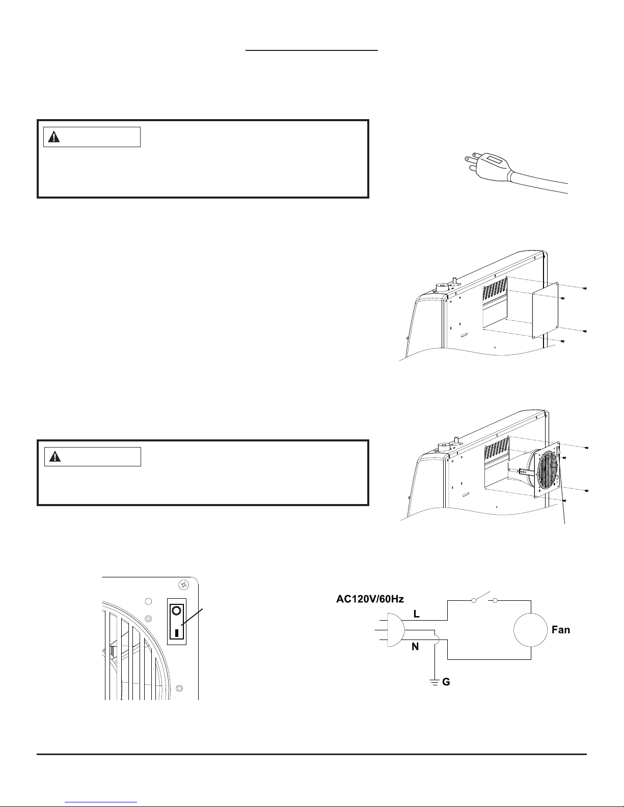
INSTALLING THE FAN (OPTIONAL)
Electrical grounding instructions: This
appliance is equipped with a three-prong
(grounding) plug for your protection against shock hazard and
should be plugged directly into a properly grounded threeprong receptacle (See Fig. 4).
1. Disconnect the wall mounted heater from the gas supply and
remove it from the wall before installing the fan accessory.
Contact a qualied service person to do this.
2. Remove the fan knock-out panel using a screwdriver (see Fig.
5). Attach the fan to the rear panel of the heater using the four
provided screws.
NOTE: Ensure the rocker switch is positioned in the upper right
corner. (see Fig. 6).
3. This fan is equipped with manual ON - OFF switch (see Fig. 7).
Set the rocker switch to “I” for manual ON, allowing the fan to
continuously run until the rocker switch is returned to the OFF
“O” position.
NOTE: If any of the original wire supplied with the heater must be
replaced, a wire of at least an equal temperature rating must be
used. Refer to Fig. 8 for the wiring diagram.
Fig. 4—Grounded Three-
Prong Receptacle
Fig. 5—Knock-out Panel
Fig. 6—Attaching the Fan
Label all wires prior to disconnection when
servicing controls. Wiring errors can cause
improper and dangerous operation. Verify proper operation after
servicing.
Fig. 7—Operating the Fan Fig. 8—Fan Wiring Diagram
Rocker Switch
Rocker Switch
13
©2017 Pinnacle Climate Technologies
Vent-Free Gas Heater User’s Manual
Installation (cont.)
POSITIONING THE HEATER
This heater can be mounted on a wall or on a oor by using the
Support Legs included with select models. For convenience
and eciency, install the heater as follows:
• In a location with easy access for operation, inspection, and service.
• In the coldest part of the room.
• A minimum of 3' (36") away from furniture and draperies.
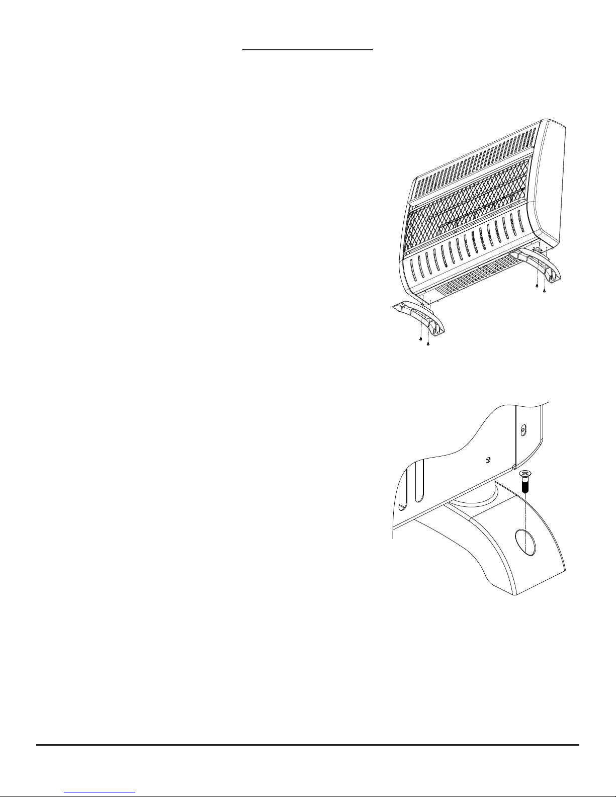
FLOOR MOUNTING (SELECT MODELS)
NOTE: This is an optional accessory and is not required for
operation of the heater. Floor mounting cannot be done in a
bedroom or bathroom and cannot be used for garage and icehouse heaters.
Before installing the Support Legs to the heater base, ensure
you have the following items:
• (2) Support Legs
• (4) Support Leg Screws
1. To prevent scratching, place a blanket onto the table where
the heater will be placed for leg installation.
Fig. 9—Attaching the Legs
Fig. 10—Securing the Legs
2. Place the back of the heater on the table with the bottom of
the heater extending past the table edge.
3. Fasten the Support Legs to the heater using the Support Leg
Screws (Fig. 9)
NOTE: If installing the heater directly on carpeting, tile, or other
combustible material, other than wood ooring, the heater must
be installed on a metal or wood panel extending the heater’s full
width and depth.
4. Once the heater is in place, secure it to the oor using the
Support Leg Screws and mounting holes found on the
heater Support Legs (See Fig. 10).
14
©2017 Pinnacle Climate Technologies
Vent-Free Gas Heater User’s Manual
Installation (cont.)
WARNING
WARNING
Min.
17 1/2"
WALL MOUNTING
ELECTRICAL, PLUMBING, OR GAS LINES MAY BE IN WALL.
Before cutting, drilling, or hammering, verify their location. If needed, contact your
electrician, plumber, or service person.
Failure to position the parts in accordance with these diagrams or failure to use only parts
specically approved with this heater may result in property damage or personal injury.
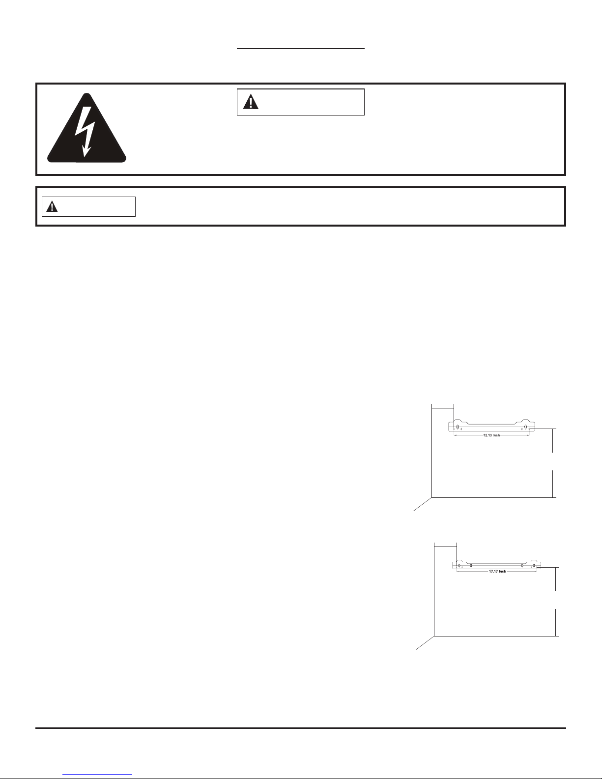
Mounting Bracket: The mounting bracket is packed in the same box as the heater but located seperately.
Methods for Attaching the Mounting Bracket to the Wall:
Use only the last hole on each end of the mounting bracket to attach the bracket to the wall. Attach the
mounting bracket to a wall in one of two ways:
1. Attaching to wall studs: This method creates the strongest hold. Insert the wood screws (4*16) through
the mounting bracket and into the wall studs.
2. Attaching to expansion bracket: This method allows you to attach the mounting bracket to solid walls
(concrete or masonry) or to hollow walls (wall areas between studs).
Fig. 11—Mounting Bracket
One method may be preferrable depending on where you install the heater,
but either method will provide a secure hold for the mounting bracket.
Clearances (Inches)
12"
B100 / B200 / R150 / R180
Marking Screw Locations:
1. Tape the mounting bracket to the wall where the heater will be
installed. Ensure the mounting bracket is level.
2. Mark the screw locations on the wall (See Fig. 11). NOTE: Mark only
the last hole on each end of mounting bracket. You will insert two (2)
Adjoining Wall
Only insert mounting
screws through last
hole on each end.
wood screws (4*16) total through these holes only.
3. Remove the mounting bracket and tape from the wall.
Attaching the Mounting Bracket to the Wall:
NOTE: The expansion bracket, wood screws, and wall hanging spacers
Min.
13"
FLOOR
B300 / R280 / R300
are in the hardware package, which is provided with the heater.
Attaching to Wall Stud Method:
1. Drill holes at the marked locations using a 9/64" drill bit.
Adjoining Wall
Only insert mounting
screws through last
hole on each end.
2. Place the mounting bracket onto the wall. Line up the last hole on
each end of the bracket with the holes drilled in the wall.
FLOOR
3. Insert the wall mounting bracket wood screws (4*16) through the
bracket and into the wall studs.
Min.
7 1/2"
Min.
4. Tighten the wood screws until the mounting bracket is rmly fastened to the wall studs.
5. Before mounting the heater, check that the wall bracket is secure.
15
©2017 Pinnacle Climate Technologies
Vent-Free Gas Heater User’s Manual
Installation (cont.)
WARNING
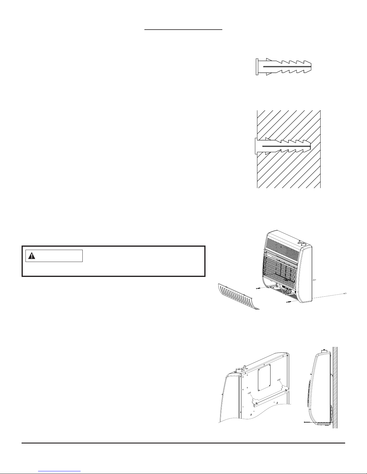
Attaching to Expansion Bracket Method:
NOTE: This method is for attaching the mounting bracket to
solid walls (concrete or masonry) or to hollow walls (wall areas
between studs).
1. Drill holes at the marked locations using a 5/16" drill bit.
For solid walls (concrete or masonry), drill at least 1" deep.
2. Insert the wall expansion pipes into each hole as shown in
Fig. 12 and 13. Tap the expansion pipes ush to the wall.
3. Place the mounting bracket onto the wall. Line up the last
hole on each end of the bracket with the expansion pipes.
4. Insert the wall mounting bracket wood screws (4*16) through
the wall mounting bracket and into the expansion pipes.
5. Tighten the wood screws until the mounting bracket is
rmly fastened to wall.
6. Before mounting the heater, ensure the mounting bracket
is secure!
Attaching the Wall Hanging Spacers to the Heater:
1. Find the spacer mounting holes on the lower right/left
sections of the heater back panel.
2. Secure two (2) wall hanging spacers to the heater back
panel using two (2) wall spacer wood screws (4*45) (See
Fig. 14a).
Fig. 12—Expansion Pipe
Fig. 13—Inserting the
Expansion Pipe
Fig. 14a—Attaching Wall
Hanging Spacers to the Heater
Failure to properly install the wall
hanging spacers may result in property
damage, personal injury or even death.
Placing the Heater on the Mounting Bracket:
1. Locate the two horizontal slots on the heater back panel.
2. Place the heater onto the mounting bracket. Slide the
horizontal slots onto the stand-out tabs on the mounting
bracket. Ensure the spacers rest evenly against the wall
(See Fig. 14b).
Fig. 14b—Mounting the Heater
Onto the Mounting Bracket
16
©2017 Pinnacle Climate Technologies
Vent-Free Gas Heater User’s Manual
Installation (cont.)
WARNING
CAUTION
WARNING
CAUTION
CONNECTING TO A GAS SUPPLY
A qualied service technician must connect heater to gas supply. Follow all local codes.
Never connect the heater to private/non-utility gas wells (commonly known as
wellhead gas).
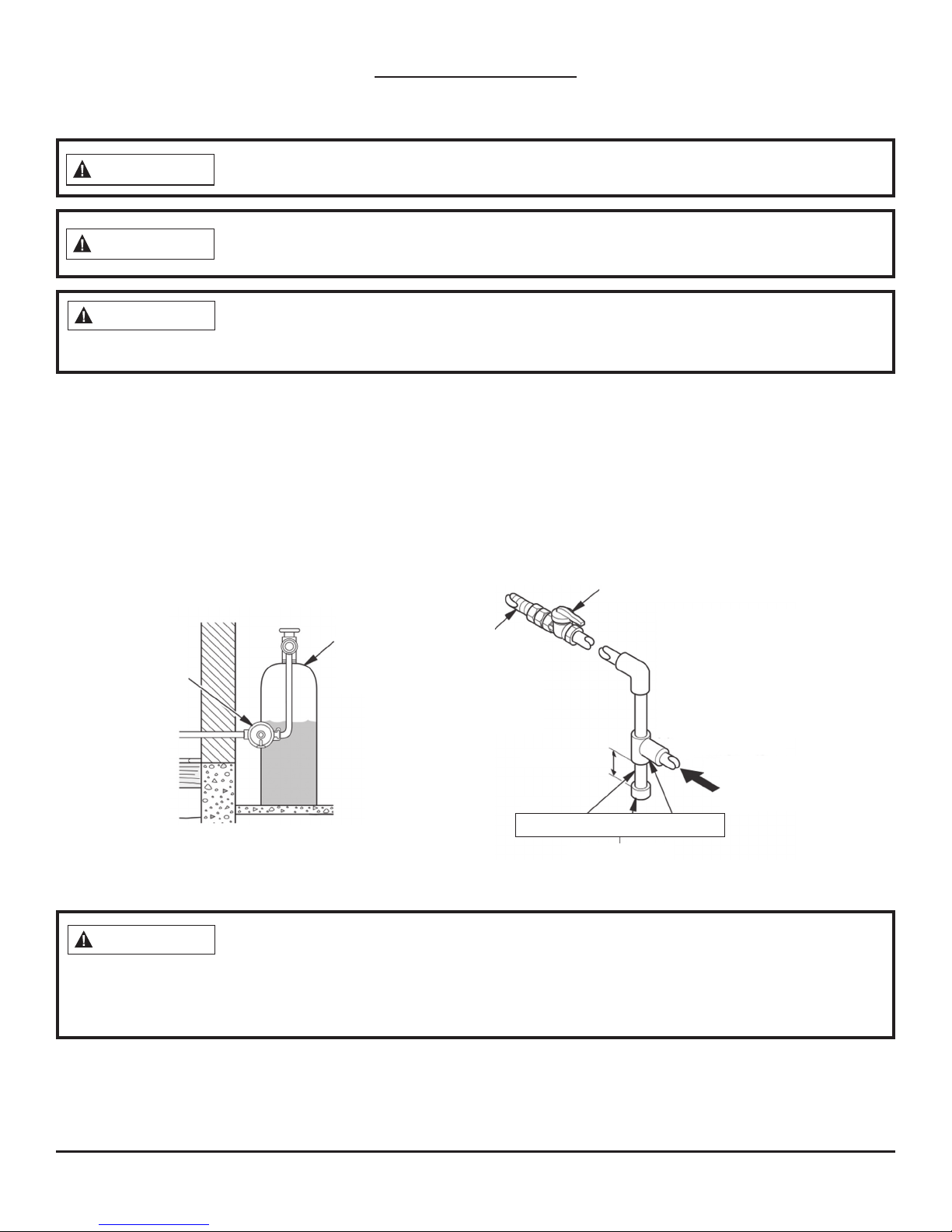
Never connect the heater directly to the gas supply. This heater requires an external
regulator (not supplied). The external regulator between the gas supply and heater
must be installed. Your gas supplier provides the external regulator for natural gas.
The installer must supply an external regulator for liquid propane. For natural gas, the gas supplier supplies
the external regulator. The external regulator reduces incoming gas pressure, and the pressure must be
reduced to between 11" and 14" of water column for propane and between 6" and 7" (B-Series) or 5" and
11" (R-Series) of water column for natural gas. Heater regulator damage could occur if the pressure of the
incoming gas is not reduced. Install the external regulator with the vent pointing down as shown in Fig. 10.
The purpose of pointing the vent down is to protect it from freezing rain or sleet.
Fig. 10—Regulator Conversion
Fig. 11—Gas Connection
Equipment Shuto Valve With
1/8" NPT Tap*
External
Regulator
with Vent
Pointing
Down
Propane/
LP Supply
Tank
Approved
Flexible
Gas Line
or 1/2"
Black Pipe
3" Minimum
Pipe Nipple Cap Tee Joint
Sediment Trap
Propane/LP
From External
Regulator (11"
W.C. to 14" W.C.
Pressure)
Natural
From Gas Meter
(5.5''
(6" W.C. to
7" W.C. Pressure—B
7''
Series; 5" W.C. to 11"
W.C. Pressure—R Series)
*The equipment shuto valve can be purchased from your local home center store.
Use only new black iron or steel pipe. Internally tinned copper tubing may be used
in certain areas, depending on your local codes. Use pipe of 1/2" diameter or greater
to allow proper volume gas to heater. If the pipe is too small, loss of pressure will occur. Installation must
include an equipment shuto valve, union, and plugged 1/8" NPT tap. The NPT tap must be located within
reach for the test gauge hook up and be upstream from heater (see Fig. 11).
IMPORTANT: Install equipment shuto valve in an accessible location. The equipment shuto valve is for
turning on or shutting o the gas to the heater. Apply pipe joint sealant lightly to the male threads. This
prevents excess sealant from going into the pipe. The heater valves may become clogged if excess sealant
gets into the pipes.
17
©2017 Pinnacle Climate Technologies
Vent-Free Gas Heater User’s Manual
Installation (cont.)
CAUTION
CAUTION
Use pipe joint sealant that is resistant to gas (propane or NG). We recommend that you
install a sediment trap in a supply line, which traps moisture and contaminants. The
sediment trap should be located within reach for cleaning and where it is not likely to freeze. Install it in the
piping system between the fuel supply and heater. This keeps contaminants from getting into the heater
controls. The heater may not run properly if the sediment trap is not installed or is installed incorrectly.
Avoid damage to the regulator. Hold the gas regulator with a wrench when connecting
into gas piping and/or ttings. NG Models: 6" to 7" W.C. (B-Series) / 5" to 11" W.C.
(R-Series). Your gas supplier provides an external regulator for natural gas.
INSTALLATION ITEMS NEEDED (NOT PROVIDED):
• 8" Adjustable Wrench
• 8" Pipe Wrench
• 3/8" Flexible Gas Line (24" Min.) or 1/2" Black Pipe
• 90 Deg. 3/8 NPT x 3/8" Flare Fitting or 3/8" Street Elbow
• Sealant (Resistant to natural or propane/LP gas)
• Shuto Valve
1. Depending on where your gas supply line is located, a variety of options are possible for routing the gas
connection lines. First, install the 3/8" tting to the heater regulator using sealant. Direct the attachment
either left or right toward the gas supply line.
NOTICE: Most building codes do not permit concealed gas connections. Check your local building code
before using a exible gas line for this installation.
2. Install the gas line to the 90 deg. tting, and attach it to the shuto valve (see Fig. 12 & 13). Depending on your
connection, it might be necessary to cut and access the hole in the side or bottom of the mantel cabinet.
3. Check all connections for gas leaks.
Fig. 12—Gas Inlet to Regulator
Fig. 13—Attaching the Flexible Gas Line
to the Equipment Shuto Valve
To Regulator
EQUIPMENT
SHUTOFF
VALVE
Flexible Gas Line or
Black Pipe to Heater
Cabinet Regulator
PROPANE/LP
To External Regulator
NATURAL GAS
To Gas Supply
18
©2017 Pinnacle Climate Technologies
Vent-Free Gas Heater User’s Manual
Installation (cont.)
WARNING
WARNING
CHECKING GAS CONNECTIONS
After installing or servicing the heater, test all gas piping and connections for leaks.
Immediately correct all leaks.
Never use an open ame to check for a leak. Apply a mixture of liquid soap and water
to all joints—bubbles may indicate a leak. Immediately correct all leaks.
Pressure Testing Gas Supply Piping System
Test Pressures in Excess Of 1/2 PSIG (3.5 kPa):
1. Disconnect the heater, including the main gas valve (control valve) and equipment shuto valve, from
the gas supply piping system. Pressures greater than 1/2 PSIG will damage the regulator.
2. Cap o the open end of the gas pipe where the equipment shuto valve was connected.
3. Open the gas supply tank valve or use compressed air to pressurize the supply piping system.
4. Check all joints of the gas supply piping system. Use a mixture of liquid soap and water in the gas joints
to check for leaks—bubbles may indicate a leak.
5. Immediately correct all leaks.
6. Reconnect the heater and equipment shuto valve to gas supply. Check reconnected ttings for leaks.
Test Pressures Equal To or Less Than 1/2 PSIG (3.5 kPa):
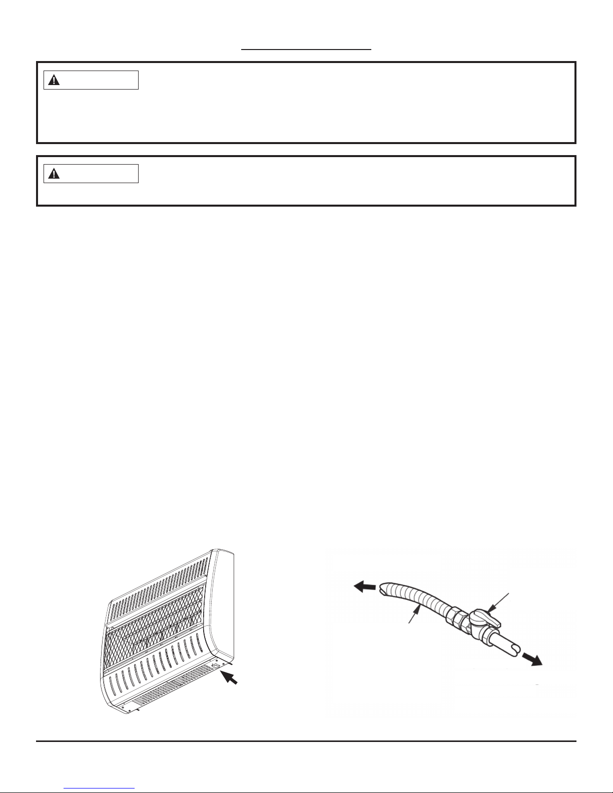
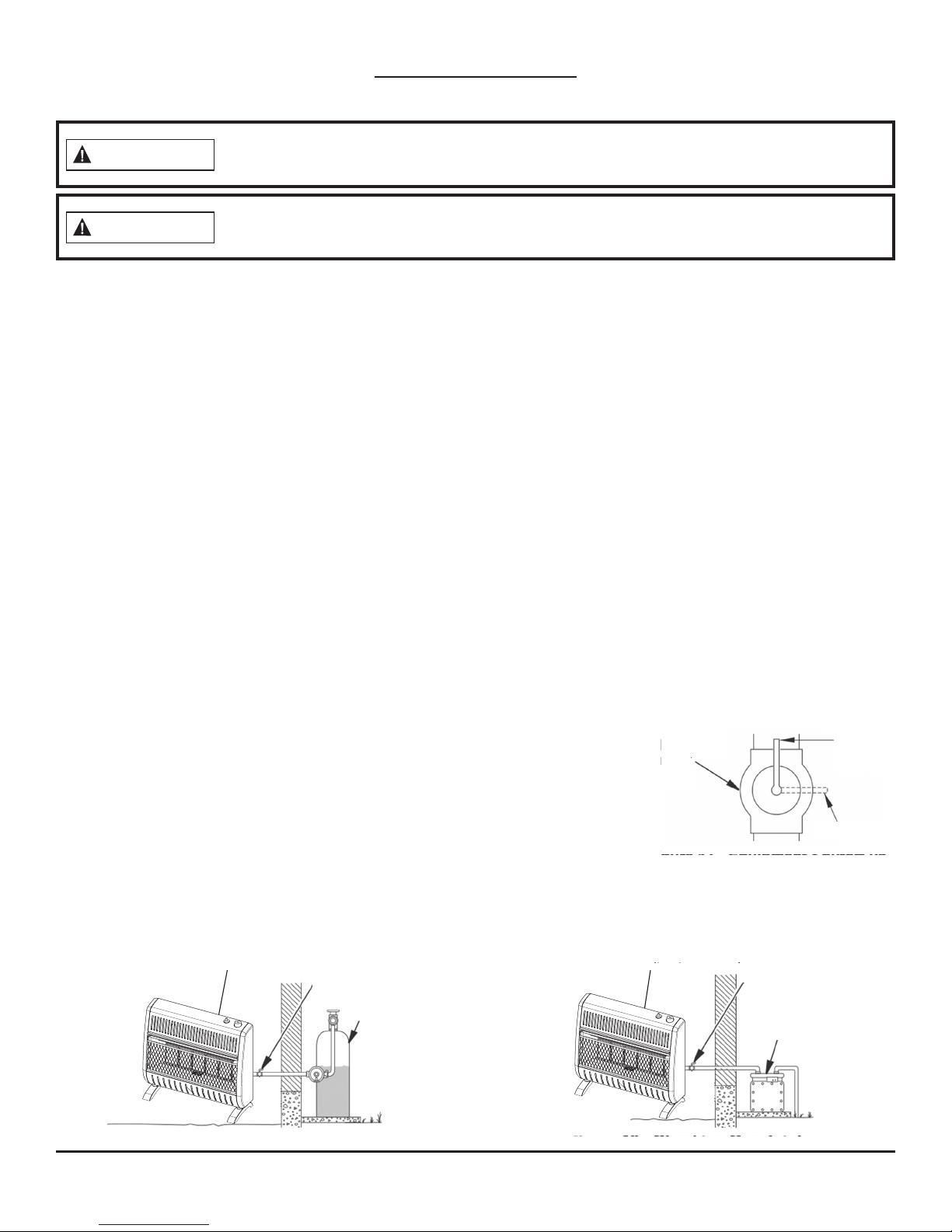
1. Close the equipment shuto valve (see Fig. 14).
2. Open the gas supply tank valve or use compressed air to pressurize the supply piping system.
3. Check all joints from the gas meter to the equipment shuto valve (see Fig. 15.1 & 15.2).
4. Use a mixture of liquid soap and water in the gas joints to check for leaks—bubbles may indicate a leak.
5. Immediately correct all leaks.
Pressure Testing Heater Gas Connections:
1. Open the equipment shuto valve (see Fig. 14).
2. Open the gas supply tank valve.
3. Ensure the control knob of the heater is in the OFF position.
4. Check all joints from the equipment shuto valve to the control
valve (see Fig. 15.1 & 15.2). Use a mixture of liquid soap and water
in the gas joints to check for leaks—bubbles may indicate a leak.
5. Light the heater (see OPERATION, pages 20–22). Check all other
internal joints for leaks.
6. Turn o the heater (see TO TURN OFF GAS TO THE HEATER, pages 21–22).
Fig. 15.1—Checking Gas Joints (Propane/LP Only)
Gas Control Valve
(Behind)
Equipment
Shuto
Valve
Propane/
LP Supply
Tank
Fig. 15.2—Checking Gas Joints (Natural Gas Only)
Equipment
Shuto
Valve
Gas Control Valve
(Behind)
Fig. 14—Equipment
Shuto Valve
Open
Closed
Equipment
Shuto Valve
Gas Meter
19
 Loading...