

REMEHA iSense Pro DIN AD280 Installation And Service Manual
Regulation
C002695-A
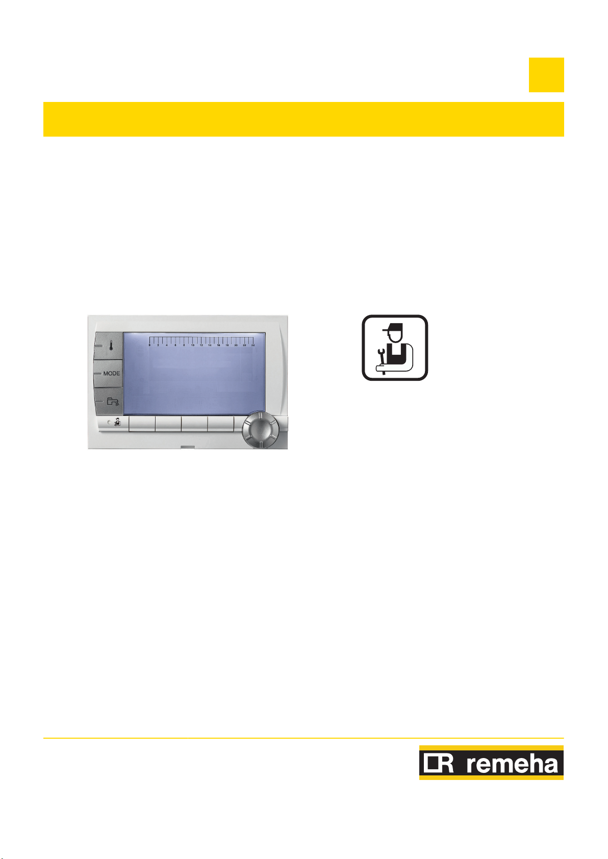
iSense Pro DIN - AD280
United Kingdom
EN
Installation and
Service Manual
300025649-001-B

Contents
1 Introduction ................................................................................................4
1.1 Symbols used .......................................................4
1.2 Abbreviations ........................................................4
1.3 General ..................................................................4
1.3.1
1.3.2 Installer's liability .....................................................5
Manufacturer's liability .............................................4
1.4 Certifications .........................................................5
2 Safety instructions and recommendations ..............................................6
2.1 Recommendations ................................................6
3 Technical description ................................................................................7
3.1 Description of the keys ........................................7
3.2 Description of the display ....................................8
3.2.1 Key functions ...........................................................8
3.2.2 Flame symbol ..........................................................8
3.2.3 Operating modes .....................................................8
3.2.4 Domestic Hot Water override ..................................9
3.2.5 Other information ....................................................9
3.3 Technical characteristics .....................................9
4 Installation ................................................................................................11
4.1 Package list .........................................................11
4.2 Installing the outside sensor .............................11
4.2.1 Choice of the location ............................................11
4.2.2 Connecting the outside sensor ..............................12
4.3 Mounting and connecting the module ..............13
4.3.1 Boiler GAS 210 ECO PRO ....................................13
4.3.2 Boiler GAS 310 ECO .............................................14
4.4 Electrical connections ........................................16
4.4.1 Recommendations ................................................16
4.4.2 Connecting a heating circuit ..................................17
4.4.3 Connecting a heating circuit and a domestic hot water
tank .......................................................................18
4.4.4 Connecting two circuits and a domestic hot water
tank .......................................................................19
4.4.5 Connecting a direct circuit, a valve circuit and a DHW
tank .......................................................................20
4.4.6 Hot water storage tank connection ........................21
1
12/04/2011 - 300025649-001-B

Contents
4.4.7 Pool connection .....................................................23
4.4.8
4.4.9 Connecting the options .........................................25
4.4.10 Connection in cascade ..........................................27
Connecting a mixed tank .......................................25
5 Operating the appliance ..........................................................................30
5.1 Powering up for the first time ............................30
5.2 Access to the various browsing levels .............30
5.2.1 User level ..............................................................30
5.2.2 Installer level .........................................................31
5.2.3 After Sales level ....................................................31
5.3 Browsing in the menus ......................................31
5.4 Reading out measured values ...........................32
5.5 Settings after powering up for the first
time ......................................................................33
5.5.1 Displaying the parameters in extended
mode .....................................................................33
5.5.2 Setting the parameters specific to the
installation .............................................................34
5.5.3 Naming the circuits and generators ......................36
5.5.4 Setting the heating curve ......................................37
5.6 Changing the settings ........................................38
5.6.1 Language selection ...............................................39
5.6.2 Calibrating the sensors .........................................39
5.6.3 Professional settings .............................................40
5.6.4 Configuring the network ........................................45
5.6.5 Return to the factory settings ................................52
6 Switching off the appliance .....................................................................53
6.1 Installation shutdown .........................................53
6.2 Frost protection ..................................................53
7 Troubleshooting .......................................................................................54
7.1 Installer's contact details ...................................54
7.2 Messages .............................................................54
7.3 Message history ..................................................55
7.4 Faults ...................................................................55
7.4.1 Deletion of sensors from the memory in the
PCB .......................................................................58
7.4.2 Deleting the IOBL 3WV modules from the memory in
the PCB ................................................................58
2
12/04/2011 - 300025649-001-B

7.5 Failure history .....................................................59
7.6 Parameter and input/output check (mode
tests) ....................................................................59
3
12/04/2011 - 300025649-001-B
iSense Pro DIN - AD280 1. Introduction
1 Introduction
1.1 Symbols used
In these instructions, various danger levels are employed to draw the
user's attention to particular information.
safeguard the user's safety, obviate hazards and guarantee correct
operation of the appliance.
DANGER
Risk of a dangerous situation causing serious physical
injury.
WARNING
Risk of a dangerous situation causing slight physical
injury.
In so doing, we wish to
1.2
Abbreviations
1.3 General
CAUTION
Risk of material damage.
Signals important information.
¼ Signals a referral to other instructions or other pages in the
instructions.
4 DHW: Domestic hot water
4 Interscenario switch: Home
to centralise and control several scenarios
4 IOBL: Carrier current home automation bus
4 3WV: 3-way valve
automation switch that can be used
12/04/2011 - 300025649-001-B
1.3.1. Manufacturer's liability
Our products are manufactured in compliance with the requirements
of the various applicable European Directives. They are therefore
delivered with [ marking and all relevant documentation.
4

1. Introduction iSense Pro DIN - AD280
In the interest of customers, we are continuously endeavouring to
make
improvements in product quality. All the specifications stated in
this document are therefore subject to change without notice.
Our liability as the manufacturer may not be invoked in the following
cases:
4 Failure to abide by the instructions on using the appliance.
4 Faulty or insufficient maintenance of the appliance.
4 Failure to abide by the instructions on installing the appliance.
1.3.2. Installer's liability
The installer is responsible for the installation and inital start up of the
appliance.
4 Read and follow the instructions given in the manuals provided
with the appliance.
4 Carry out installation in compliance with the prevailing legislation
and standards.
4 Perform the initial start up and carry out any checks necessary.
4 Explain the installation to the user.
4 If a maintenance is necessary, warn the user of the obligation to
check the appliance and maintain it in good working order.
4 Give all the instruction manuals to the user.
The installer must respect the following instructions:
1.4 Certifications
This product complies to the requirements to the european directives
and following standards:
4 2006/95/EC Low Voltage Directive.
EN60.335.1.
4 2004/108/EC Electromagnetic Compatibility Directive. Generic
standards: EN1000-6-3 , EN 61000-6-1.
Reference Standard:
5
12/04/2011 - 300025649-001-B
iSense Pro DIN - AD280 2. Safety instructions and recommendations
2 Safety instructions and
recommendations
2.1 Recommendations
WARNING
Only qualified professionals are authorised to work on the
appliance and the instalation.
The appliance should be on Summer or Antrifreeze mode rather than
switched off to guarantee the following functions:
4 Anti blocking of pumps.
4 Frost protection.
12/04/2011 - 300025649-001-B
6
A000866-A
bar
STD
t
0
2 4 6 8 10 12 14 16 18 22 2420
p
b
AUTO
x
c
r
j
M
g
m
A
B
C
D
E
F
(
'
3. Technical description iSense Pro DIN - AD280
3 Technical description
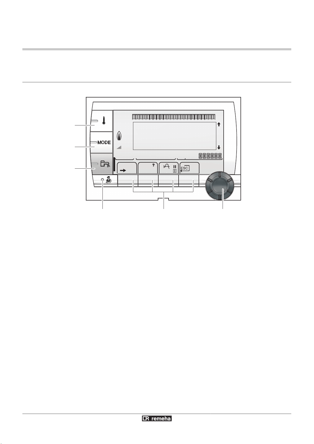
3.1 Description of the keys
A
B
C
D
E
F
Temperature setting key (heating, DHW, swimming pool)
Operating mode selection key
DHW override key
Key to access the parameters reserved for the installer
Keys on which the function varies as and when selections
are made
Rotary setting button:
4 Turn
4 Press the rotary button to access the menu selected
the rotary button to scroll through the menus or
modify a value
or confirm a value modification
7
12/04/2011 - 300025649-001-B
bar
r
STD
(
'
t
0 2 4 6 8 10 12 14 16 18 22 242
0
C002696-A
p
b
AUTO
x
c
r
j
L
g
m
bar
STD
t
0
2 4 6 8 10 12 14 16 18 22 2420
C002701-B
p
b
AUTO
x
c
r
j
M
g
m
bar
STD
t
0
2 4 6 8 10 12 14 16 18 22 2420
C002697-B
p
b
AUTO
x
c
r
j
M
g
m
iSense Pro DIN - AD280 3. Technical description
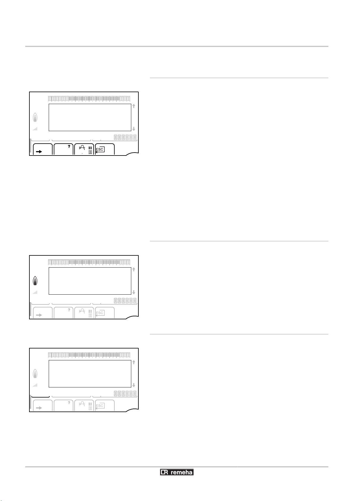
3.2 Description of the display
3.2.1. Key functions
>
(
'
?
f
STD
b
Access to the various menus
Used to scroll through the menus
Used to scroll through the parameters
The symbol is displayed when help is available
Used to display the curve of the parameter selected
Reset of the time programmes
Selection of comfort mode or selection of the days to be
programmed
v
Selection of reduced mode or deselection of the days to
be programmed
j
ESC
Back to the previous level
Back to the previous level without saving the
modifications made
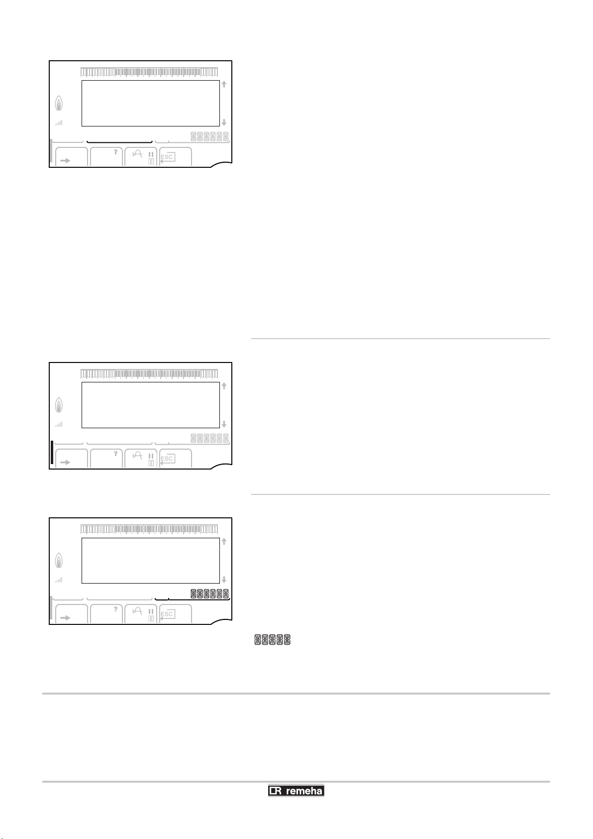
3.2.2. Flame symbol
4 The symbol is displayed:
4 The symbol is not displayed: The burner is off.
The burner is operating.
12/04/2011 - 300025649-001-B
3.2.3. Operating modes
p
b
Summer mode: The heating is off. Domestic hot water
continues to be produced
WINTER mode: Heating
and domestic hot water working
8
bar
STD
t
0
2 4 6 8 10 12 14 16 18 22 2420
C002698-B
p
b
AUTO
x
c
r
j
M
g
m
bar
STD
t
0
2 4 6 8 10 12 14 16 18 22 2420
C002707-A
p
b
AUTO
x
c
r
j
M
g
m
bar
STD
t
0
2 4 6 8 10 12 14 16 18 22 2420
C002699-B
p
b
AUTO
x
c
r
j
M
g
m
3. Technical description iSense Pro DIN - AD280
AUTO
Operation in automatic mode according to the timer
programme
x
Comfort mode: The symbol is displayed when a DAY
override (comfort) is activated
4 Flashing symbol: Temporary override
4 Steady symbol: Permanent override
m
Reduced mode: The symbol is displayed when a NIGHT
override (reduced) is activated
4 Flashing symbol: Temporary override
4 Steady symbol: Permanent override
g
Holiday mode: The symbol is displayed when a HOLIDAY
override (antifreeze) is activated
4 Flashing symbol: Holiday mode programmed
4 Steady symbol: Holiday mode active
m
Manual mode
3.2.4. Domestic Hot Water override
A bar is displayed when a DHW override is activated:
4 Flashing bar: Temporary override
4 Steady bar: Permanent override
3.2.5. Other information
r
w
M
The symbol is displayed when domestic hot water
production is running
Valve indicator: The symbol is displayed when a 3-way
valve is connected
4 x : 3-way valve open
4 c : 3-way valve closed
The symbol is displayed when the pump is operating
Name of the circuit for which the parameters are displayed
3.3 Technical characteristics
Electricity supply: 230 V - 50 Hz
9
12/04/2011 - 300025649-001-B
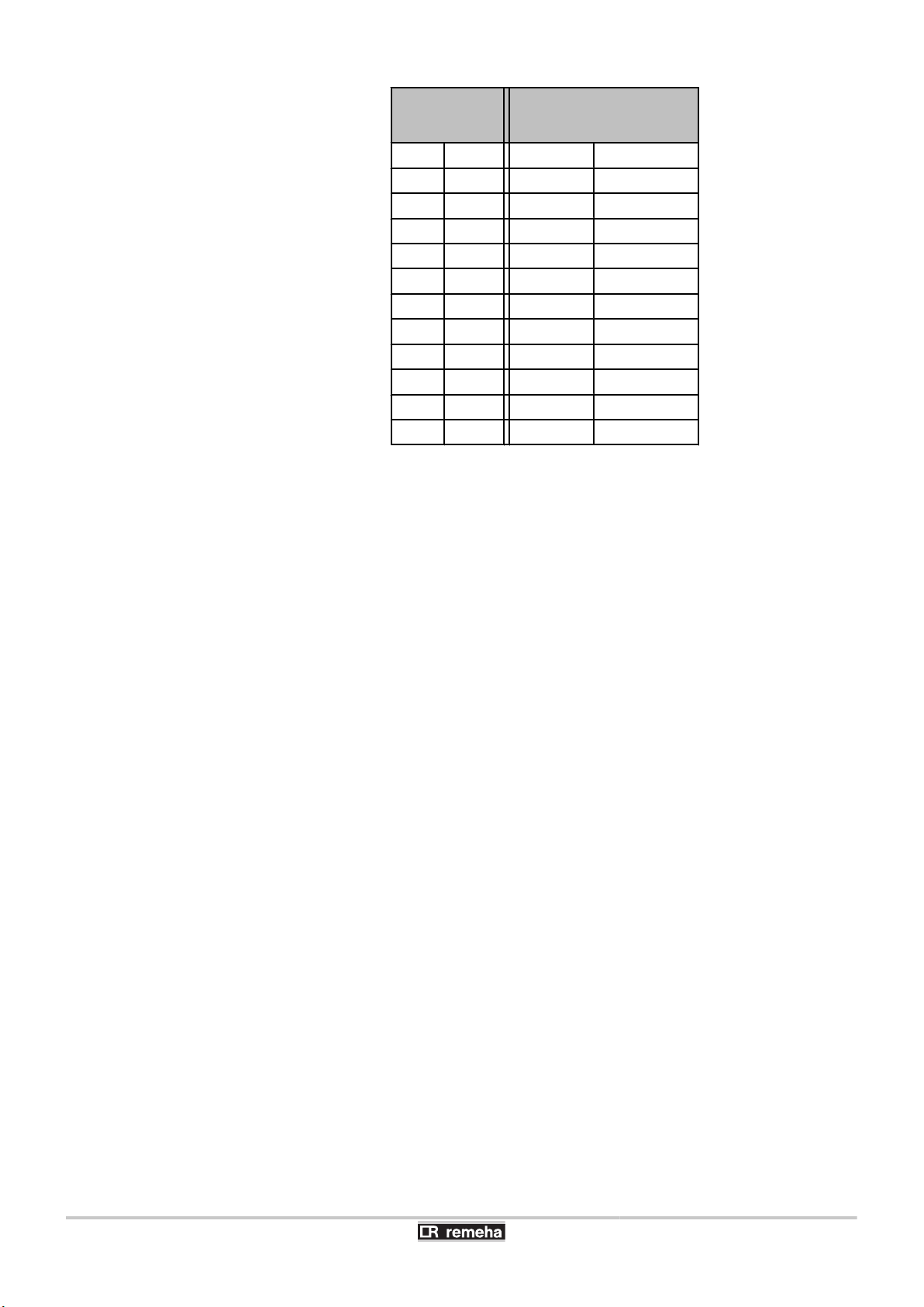
iSense Pro DIN - AD280 3. Technical description
Outside sensor Outlet sensor circuit B+C
Domestic hot water sensor
System sensor
-20 °C
-16 °C
-12 °C
-8 °C
-4 °C
0 °C
4 °C
8 °C
12 °C
16 °C
20 °C
24 °C
2392 ¨
2088 ¨
1811 ¨
1562 ¨
1342 ¨
1149 ¨
984 ¨
842 ¨
720 ¨
616 ¨
528 ¨
454 ¨
0 °C
10 °C
20 °C
25 °C
30 °C
40 °C
50 °C
60 °C
70 °C
80 °C
90 °C
32014 ¨
19691 ¨
12474 ¨
10000 ¨
8080 ¨
5372 ¨
3661 ¨
2535 ¨
1794 ¨
1290 ¨
941 ¨
12/04/2011 - 300025649-001-B
10

4. Installation iSense Pro DIN - AD280
4 Installation
4.1 Package list
The delivery includes:
4 The iSense Pro DIN module
4 Electrical harness
4 Extension cable marked
PRO boiler)
4 Outside sensor
4 Flow sensor (x2)
4 DHW sensor
4 Earth terminal block + 2 screws
4 Installation and Service Manual
4 User Guide.
K1 (For connecting a GAS 210 ECO
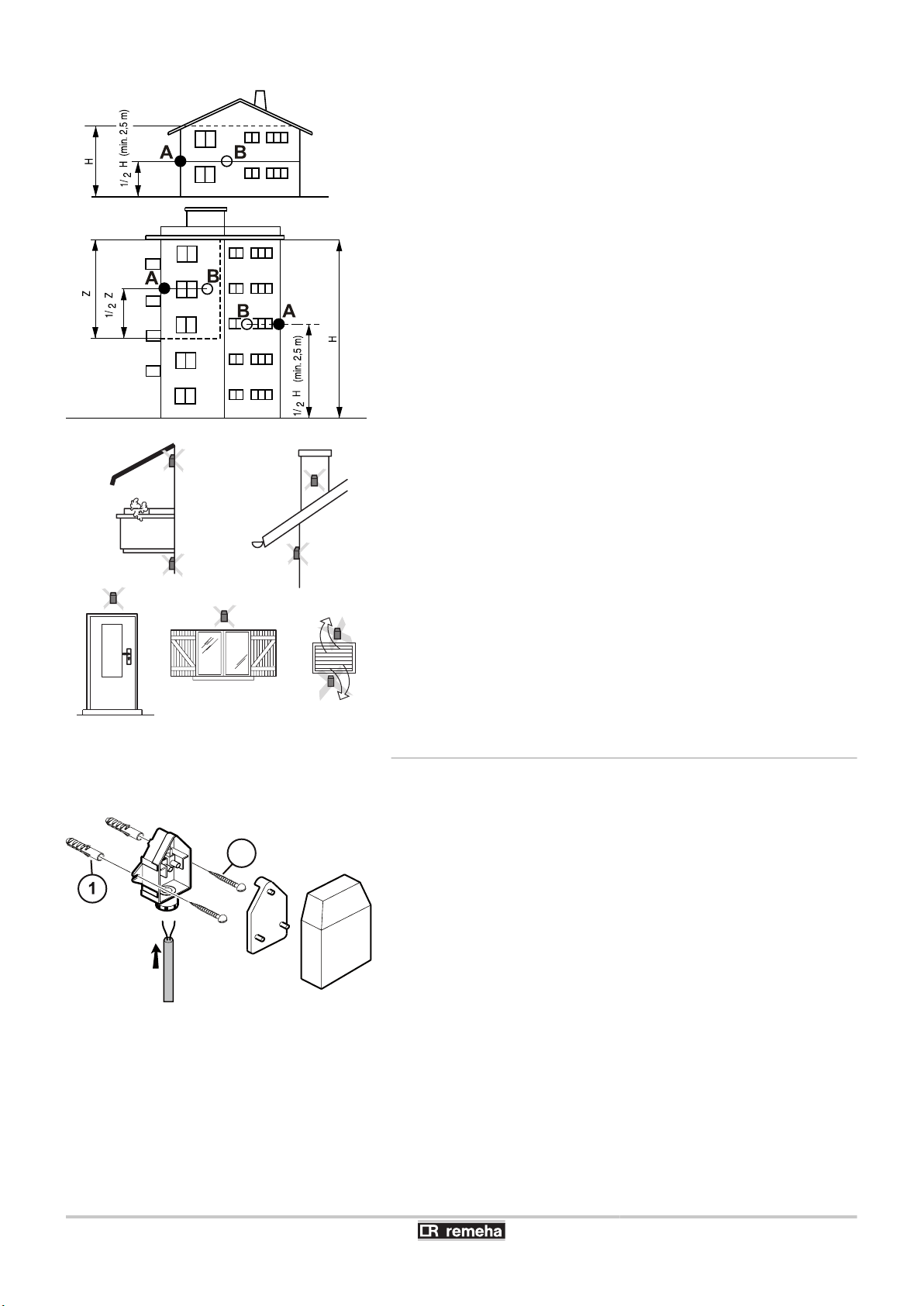
4.2 Installing the outside sensor
4.2.1. Choice of the location
It is important to select a place that allows the sensor to measure the
outside conditions correctly and effectively.
Advised positions:
4 on one face of the area to be heated, on the north if possible
4 half way up the wall in the room to be heated
4 under the influence of meteorological variations
4 protected from direct sunlight
4 easy to access
11
12/04/2011 - 300025649-001-B
8800N001-C
8800N002-C
8800N003-C
2
iSense Pro DIN - AD280 4. Installation
A
B
H
Z
Recommended position
Possible position
Inhabited height controlled by the sensor
Inhabited area controlled by the sensor
Positions to be avoided:
4 masked by a building element (balcony, roof, etc.)
4 close to a disruptive heat source (sun, chimney, ventilation grid,
etc.)
4.2.2.
Connecting the outside sensor
Mount the sensor using the screws and dowels provided.
A
Z
Inserts
Ø4 wood screw
12/04/2011 - 300025649-001-B
12
2
1
3
4x
2
1
1
1
4x
2
2
x
C003311-B
K2
K
1
K1
K1
3
3
4
OT
1
2
3
4
b
ar
STD
0 2 4 6 8 1
0
1
2 1
4 16 1
8
2
2 24
20
AU
T
O
C003312-B
4. Installation iSense Pro DIN - AD280
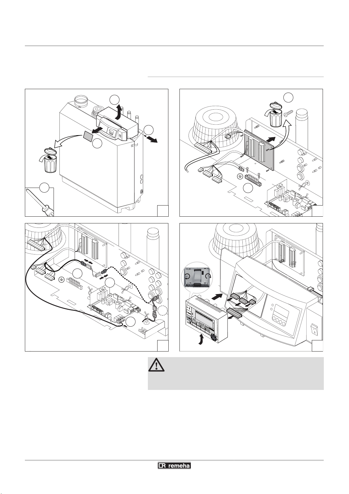
4.3 Mounting and connecting the module
4.3.1. Boiler GAS 210 ECO PRO
CAUTION
Step 3: Connect the extension cable K1 between
connectors A and Z.
13
12/04/2011 - 300025649-001-B
1
2
C003313-A
3
4
C003314-B
C003315-A
5 6
iSense Pro DIN - AD280 4. Installation
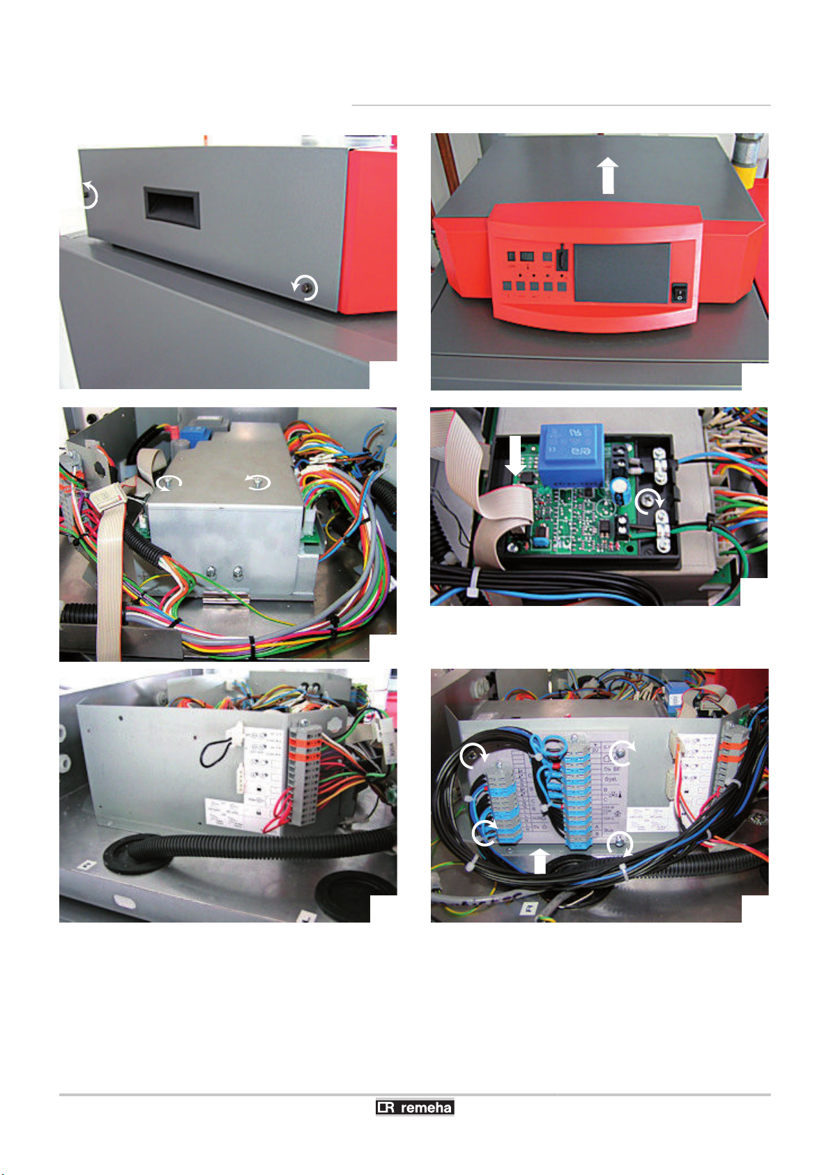
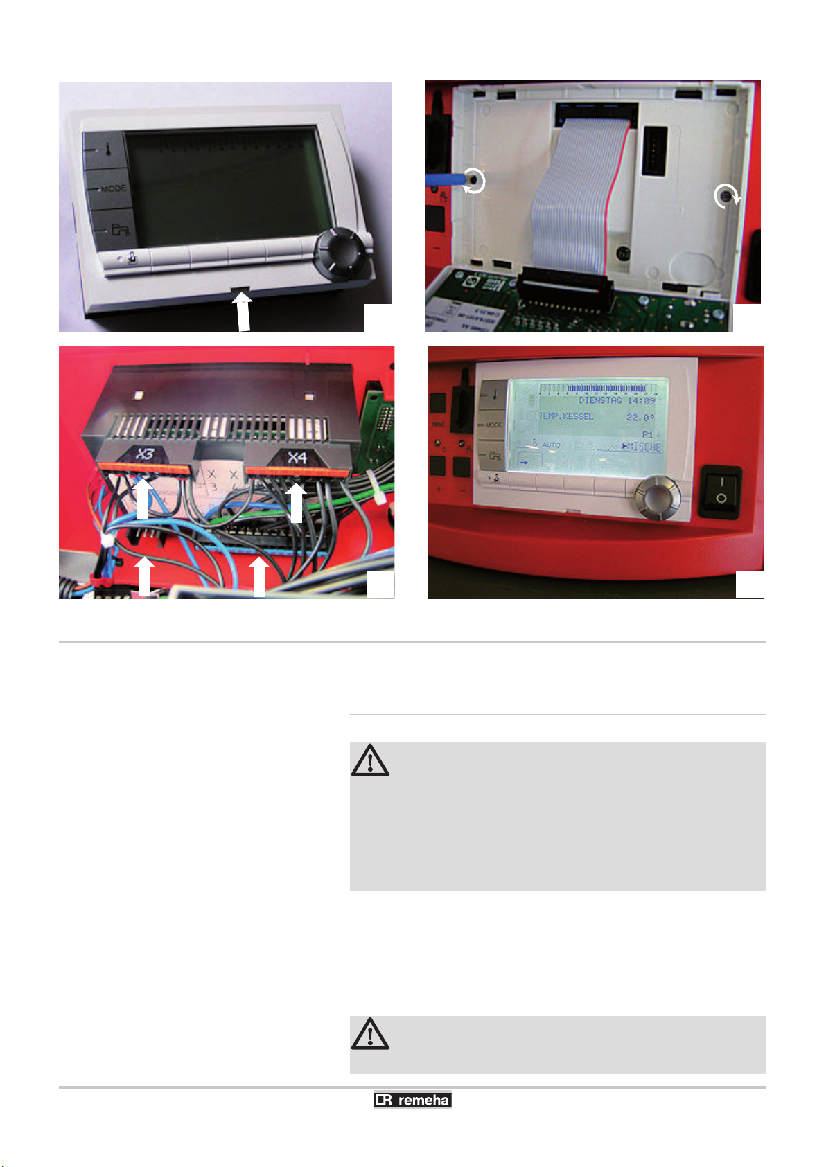
4.3.2. Boiler GAS 310 ECO
12/04/2011 - 300025649-001-B
14

7
8
K1
K1
K1
X16
C003316-A
C003317-C
9 10
K 2
X 16
X 16
C003318-B
11
12
4. Installation iSense Pro DIN - AD280
15
12/04/2011 - 300025649-001-B
14
13
C003319-B
X4
X3
X2
X1
16
15
C003320-B
iSense Pro DIN - AD280 4. Installation
4.4 Electrical connections
4.4.1. Recommendations
WARNING
4 Only
4 The boiler is entirely pre-wired. Do not modify the
4 Earth the appliance before making any electrical
Make the electrical connections of the boiler according to:
4 The instructions of the prevailing standards.
4 The instructions on the electrical diagrams provided with the
boiler.
4 The recommendations in the instructions.
qualified professionnals may carry out electrical
connections, always with the power off.
connections inside the control panel.
connections.
12/04/2011 - 300025649-001-B
CAUTION
Separate the sensor cables from the 230 V cables.
16
2
4
6
3
1
5
NN N L N L N L N L
+ -
AUX
BBC C
B 0V B AC
0-10V
S Syst.
BUS
AF BF
C002815-A
4. Installation iSense Pro DIN - AD280
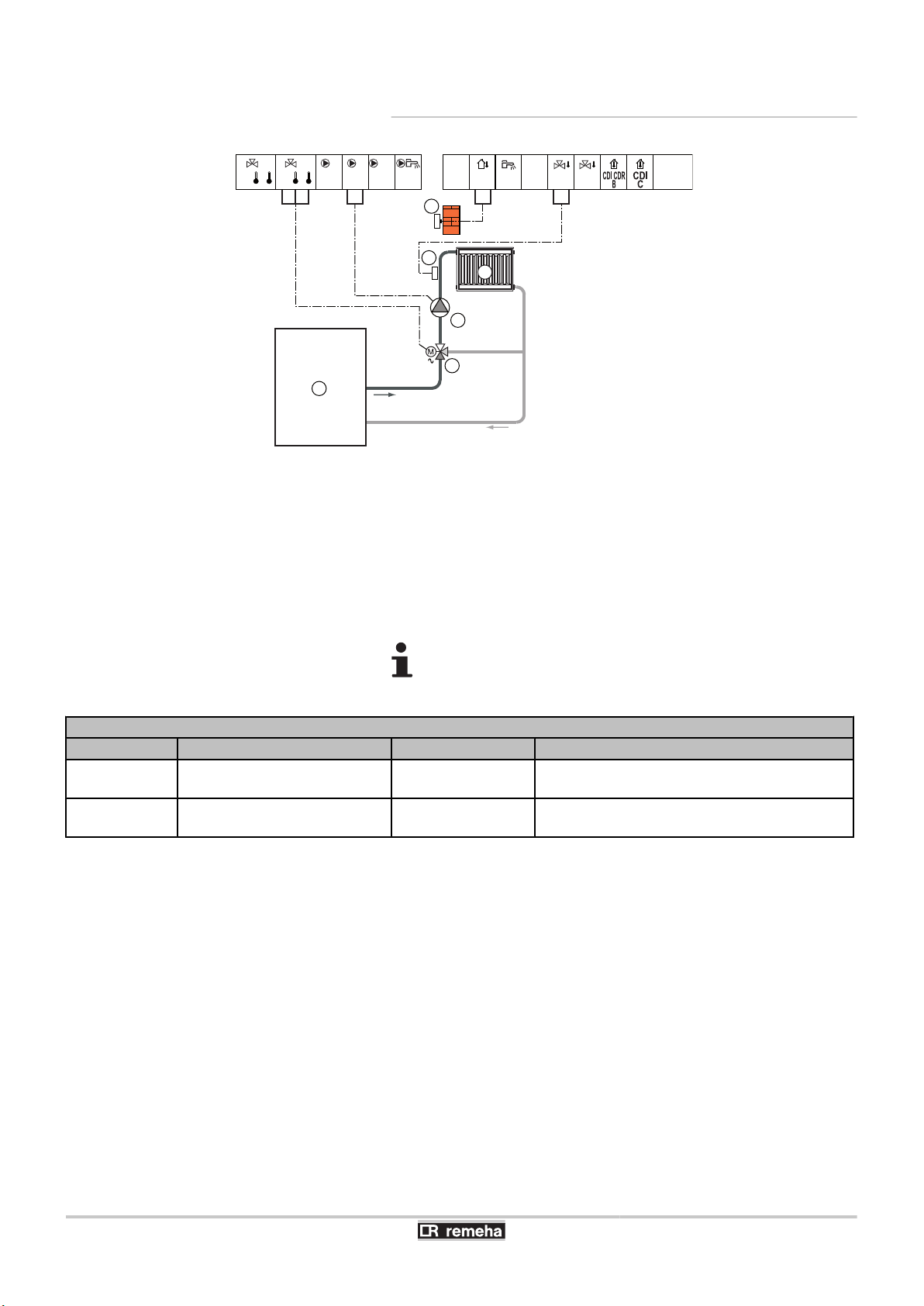
4.4.2. Connecting a heating circuit
A
Z
E
R
T
Y
3 way valve circuit B
Heating pump circuit B
Outlet sensor circuit B
Heating circuit B
Outside sensor
Boiler
Earth the various pumps and 3-way valves.
Settings to be made for this type of installation
Parameters Access Settings to be made See chapter
CIRC.CURVE B
MAX. CIRC. B
Installer level
#SECONDARY INSTAL.P menu
Installer level
#SECONDARY LIMITS menu
To be customised
To be customised
¼ "Setting the heating curve", page 37
¼ "Professional settings", page 40
17
12/04/2011 - 300025649-001-B
2
4
6
3
5
1
10
7
8
9
NN N L N L N L N L
+ -
AUX
BBC C
B 0V B AC
0-10V
S Syst.
BUS
AF
BF
C002816-A
iSense Pro DIN - AD280 4. Installation
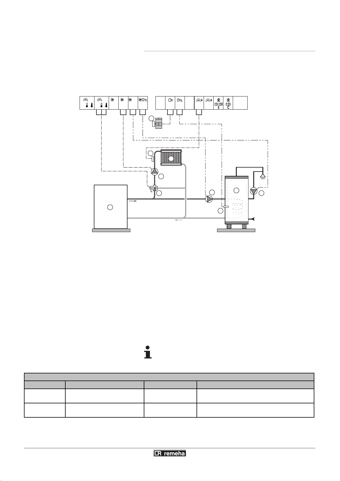
4.4.3. Connecting a heating circuit and a
domestic hot water tank
3 way valve circuit B
Heating pump circuit B
Outlet sensor circuit B
Heating circuit B
Outside sensor
Boiler
DHW storage tank
DHW sensor
Domestic circulation loop pump (Optional)
D.H.W. load pump
Earth the various pumps and 3-way valves.
A
Z
E
R
T
Y
U
I
O
P
Settings to be made for this type of installation
Parameters Access Settings to be made See chapter
CIRC.CURVE B
MAX. CIRC. B
Installer level
#SECONDARY INSTAL.P menu
Installer level
#SECONDARY LIMITS menu
To be customised
To be customised
¼ "Setting the heating curve", page 37
¼ "Professional settings", page 40
12/04/2011 - 300025649-001-B
18
2
4
6
3
5
1
10
7
8
9
12
14
13
11
NN N L N L N L N L
+ -
AUX
BBC C
B 0V B AC
0-10V
S Syst.
BUS
AF BF
C002817-A
4. Installation iSense Pro DIN - AD280
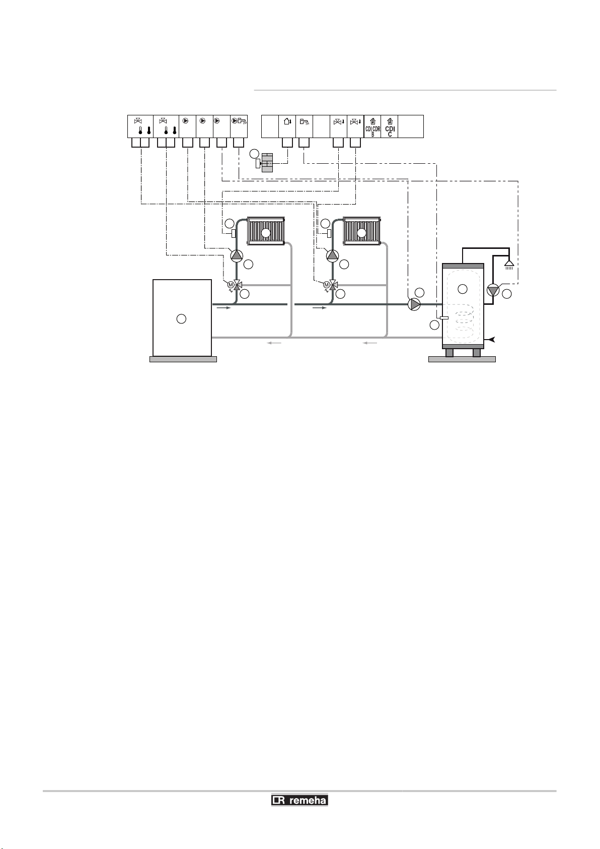
4.4.4. Connecting
water tank
two circuits and a domestic hot
A
Z
E
R
T
Y
U
I
O
P
a
z
e
r
3 way valve circuit B
Heating pump circuit B
Outlet sensor circuit B
Heating circuit B
Outside sensor
Boiler
DHW storage tank
DHW sensor
Domestic circulation loop pump (Optional)
D.H.W. load pump
3 way valve circuit C
Heating pump circuit C
Outlet sensor circuit C
Heating circuit C
19
12/04/2011 - 300025649-001-B
 Loading...