

Page 1
2U Storage System
User Manual
SS2280
Jun. 2007 (Revision C)
P/N: 1230B0033901
Page 2

Copyright Notice
All rights, including copyright, in the content of this manual are owned or controlled by IESC
and protected by the Taiwan and international copyright act.
No one may, transmit, adapt, assign, compile, rent, sale, change, copy, reproduce, distribute,
publish, display, broadcast, or use in any way the content of this manual, in whole or in part,
for any other purpose whatsoever without the prior written permission of IESC.
Trademarks
All product names or brands mentioned herein are the trademarks of IESC, its subsidiaries or
other respective owners in Taiwan, United States and other countries.
Disclaimer
This manual provides the information in relation to the set-up and installation of the product
herein. Nothing herein may be construed as granting any right or license relating to any
intellectual property rights of this manual or product. Unless otherwise provided in the
Purchase and Sale Agreement for this product, manufacturer and distributor of this product
will not be liable whatsoever relating to the distribution and/or use of this product. In addition,
manufacturer and distributor of this product hereby specifically disclaim any express or
implied warranties of merchantability, fitness for a particular purpose, or non-infringement of
third party rights in connection with this product.
Manufacturer of this product may have the right to change specifications and product
descriptions at any time without notice.
Page 3

Contents
About This Manual ........................................................................................................................i
Conventions.................................................................................................................................i
Safety Symbols...........................................................................................................................ii
Safety Precautions..................................................................................................................... iii
Operation Safety .................................................................................................................... iii
Electrical Safety...................................................................................................................... iii
Battery Replacement Safety...................................................................................................iv
Laser Peripherals or Devices Safety.......................................................................................v
Intended Application Uses.......................................................................................................v
Site Selection ..........................................................................................................................v
Tools Required ........................................................................................................................v
Regulatory and Integration Information...................................................................................... vi
Regulatory Compliance Identification Numbers...................................................................... vi
Product Regulatory Compliance.............................................................................................vi
Power Cords..........................................................................................................................viii
1 Introduction ........................................................................................................................1-1
1.1 Audience Assumptions..................................................................................................1-1
1.2 Manual Organization.....................................................................................................1-1
1.3 Packing Checklist..........................................................................................................1-1
1.4 Specifications................................................................................................................1-2
1.5 Product Features...........................................................................................................1-2
1.6 System Overview ..........................................................................................................1-4
1.6.1
Server Chassis Layout...........................................................................................1-4
1.6.2 Front View..............................................................................................................1-5
1.6.3 Back View ..............................................................................................................1-5
1.6.4 Buttons and System LED Information....................................................................1-6
2 Motherboard .......................................................................................................................2-1
2.1 Motherboard Layout......................................................................................................2-1
2.2 Screw Holes..................................................................................................................2-3
2.3 Processor......................................................................................................................2-4
2.3.1 To remove the heat sink.........................................................................................2-5
2.3.2 To install the heat sink............................................................................................2-6
2.3.3 To remove the processor........................................................................................2-7
2.3.4 To install the processor ..........................................................................................2-8
2.3.5 To remove the heat sink socket..............................................................................2-9
2.3.6 To install the heat sink socket.................................................................................2-9
2.4 System Memory..........................................................................................................2-10
2.4.1 To remove a DIMM...............................................................................................2-11
Page 4

2.4.2 To install a DIMM..................................................................................................2-11
2.5 System Configuration Jumper.....................................................................................2-12
3 Hardware Operations.........................................................................................................3-1
3.1 Before You Start ............................................................................................................3-1
3.1.1 Power Off...............................................................................................................3-1
3.2 Chassis Cover...............................................................................................................3-2
3.3 Motherboard..................................................................................................................3-4
3.4 Power Distribution Board...............................................................................................3-6
3.5 Power Supplies .............................................................................................................3-7
3.6 IDE Converter Board.....................................................................................................3-9
3.7 System Fan Assemblies..............................................................................................3-11
3.8 SATA&SAS Backplane................................................................................................3-14
3.9 SATA&SAS HDDs.......................................................................................................3-17
3.10 Optional Riser Cards...................................................................................................3-19
3.11 Daughter Card.............................................................................................................3-23
3.12 Fan Duct......................................................................................................................3-27
4 Cable Connections.............................................................................................................4-1
4.1 Connectors and Pin 1 Locations ...................................................................................4-1
4.2 Cable Connections........................................................................................................4-2
4.2.1 JBOD Cable...........................................................................................................4-2
4.2.2 Front Panel Cable..................................................................................................4-3
4.2.3 Power Cables.........................................................................................................4-6
4.2.4 SATA&SAS HDD Cable..........................................................................................4-7
4.2.5 Backplane Power Cables.......................................................................................4-7
4.2.6 Power Supply I
4.2.7 System Fan Cables................................................................................................4-9
4.2.8 Chassis Intrusion Cable.......................................................................................4-11
4.3 Power Supply..............................................................................................................4-11
4.4 Power On....................................................................................................................4-12
Appendix China RoHS Regulations...........................................................................................I
2
C Cable .........................................................................................4-8
List of Figures
Figure 1-1 Product Introduction..........................................................................................1-2
Figure 1-2 Server Chassis Layout......................................................................................1-4
Figure 1-3 Front View.........................................................................................................1-5
Figure 1-4 Back View.........................................................................................................1-5
Figure 1-5 Front Panel.......................................................................................................1-6
Figure 1-6 Back View LEDs ...............................................................................................1-6
Figure 2-1 Connectors and Component Locations.............................................................2-1
Figure 2-2 Screws Placement............................................................................................2-3
Page 5

Figure 2-3 Processor Location...........................................................................................2-4
Figure 2-4 Pulling up the Two Levers.................................................................................2-5
Figure 2-5 Lifting the Heat Sink up.....................................................................................2-5
Figure 2-6 Pulling up the Two Levers.................................................................................2-6
Figure 2-7 Placing the Heat Sink on Top of the Processor...............................................2-6
Figure 2-8 Locking the Two Levers....................................................................................2-6
Figure 2-9 Opening the Load Plate....................................................................................2-7
Figure 2-10 Lifting the Processor out of the Socket...........................................................2-7
Figure 2-11 Closing the Load Plate....................................................................................2-7
Figure 2-12 Placing on the PnP Cap..................................................................................2-8
Figure 2-13 Pointing the Golden Corner toward the Socket...............................................2-8
Figure 2-14 Releasing the Screws.....................................................................................2-9
Figure 2-15 Lifting up the Heat Sink Socket.......................................................................2-9
Figure 2-16 Installing the Heat Sink Base Socket..............................................................2-9
Figure 2-17 System Memory Location.............................................................................2-10
Figure 2-18 Lifting the DIMM out of the Socket................................................................2-11
Figure 2-19 Pressing the Retaining Clips Outward..........................................................2-11
Figure 2-20 Inserting the DIMM into the Socket...............................................................2-11
Figure 2-21 System Configuration Jumper ......................................................................2-12
Figure 3-1 Pressing the Power Button...............................................................................3-2
Figure 3-2 Unplugging the Power Cords............................................................................3-2
Figure 3-3 Removing the Top Cover..................................................................................3-3
Figure 3-4 Sliding the Top Cover to the Front....................................................................3-3
Figure 3-5 Tightening the Screw........................................................................................3-3
Figure 3-6 Motherboard Location.......................................................................................3-4
Figure 3-7 Removing the Motherboard..............................................................................3-5
Figure 3-8 Power Distribution Board Location ...................................................................3-6
Figure 3-9 Removing the Power Distribution Board...........................................................3-6
Figure 3-10 Installing the Power Distribution Board...........................................................3-7
Figure 3-11 Location of Power Supplies ............................................................................3-7
Figure 3-12 Removing the Power Supply ..........................................................................3-8
Figure 3-13 Installing the Power Supply ............................................................................3-8
Figure 3-14 IDE Converter Board ......................................................................................3-9
Figure 3-15 IDE Converter Board Location........................................................................3-9
Figure 3-16 Removing the IDE Flash Card......................................................................3-10
Figure 3-17 Unscrewing the IDE Converter Board...........................................................3-10
Figure 3-18 Removing the IDE Converter Board.............................................................3-10
Figure 3-19 Location of System Fan Assemblies.............................................................3-11
Figure 3-20 Lifting the System Fan out of the System Fan Cage (1)...............................3-12
Figure 3-21 Lifting the System Fan out of the System Fan Cage (2)...............................3-12
Figure 3-22 Unlocking the System Fan Cage..................................................................3-13
Figure 3-23 Removing the System Fan Cage..................................................................3-13
Figure 3-24 Putting the System Fan Cage into the Chassis............................................3-13
Figure 3-25 Front & Back View of SATA&SAS Backplane...............................................3-14
Page 6

Figure 3-26 Backplane Location ......................................................................................3-15
Figure 3-27 Removing the Backplane Assembly .............................................................3-15
Figure 3-28 Removing the Backplane..............................................................................3-16
Figure 3-29 Fixing the Backplane to the Backplane Bracket............................................3-16
Figure 3-30 Installing the Backplane Assembly ...............................................................3-16
Figure 3-31 Location of HDD Assemblies........................................................................3-17
Figure 3-32 Releasing the Lev er......................................................................................3-17
Figure 3-33 Sliding the HDD Assembly............................................................................3-18
Figure 3-34 Placing the HDD to the HDD tray .................................................................3-18
Figure 3-35 Securing HDD to the HDD Tray....................................................................3-18
Figure 3-36 Inserting the HDD Assembly.........................................................................3-19
Figure 3-37 Pushing the Lever Back in Place..................................................................3-19
Figure 3-38 PCI-X/PCI-E Riser Card ...............................................................................3-20
Figure 3-39 PCI-E Riser Card..........................................................................................3-20
Figure 3-40 Riser Card Assembly Location......................................................................3-21
Figure 3-41 Lifting the Riser Card Assembly....................................................................3-21
Figure 3-42 Removing the Expansion Card.....................................................................3-22
Figure 3-43 Releasing the Riser Card..............................................................................3-22
Figure 3-44 Removing the Riser Card .............................................................................3-22
Figure 3-45 2CH SAS RAID Daughter Card....................................................................3-23
Figure 3-46 SAS Daughter Card Assembly Location.......................................................3-23
Figure 3-47 Removing the Daughter Card Assembly.......................................................3-24
Figure 3-48 Installing the Daughter Card Assembly.........................................................3-24
Figure 3-49 Connecting the SAS JBOD Cable ................................................................3-25
Figure 3-50 Removing the Daughter-card Latch..............................................................3-25
Figure 3-51 Installing the Daughter-card Latch................................................................3-26
Figure 3-52 I-button Location...........................................................................................3-26
Figure 3-53 Removing the I-button ..................................................................................3-26
Figure 3-54 Installing the I-button ....................................................................................3-27
Figure 3-55 Fan Duct Location ........................................................................................3-27
Figure 3-56 Removing the Fan Duct................................................................................3-28
Figure 4-1 Locations of Connectors and Pin 1...................................................................4-1
Figure 4-2 JBOD Introduction ............................................................................................4-2
Figure 4-3 Connecting the Front Panel IDE Cable.............................................................4-3
Figure 4-4 Front Panel Cable Connection Layout..............................................................4-3
Figure 4-5 Connecting the Front Panel Cable....................................................................4-4
Figure 4-6 Releasing the Screws.......................................................................................4-4
Figure 4-7 Removing the Front Panel................................................................................4-4
Figure 4-8 Releasing the Buttons ......................................................................................4-5
Figure 4-9 Pulling out the Front Panel Cable.....................................................................4-5
Figure 4-10 Connecting the Main Power Cable.................................................................4-6
Figure 4-11 Connecting the Processor Power Cable .........................................................4-6
Figure 4-12 Connecting the SATA&SAS HDD Cable.........................................................4-7
Figure 4-13 Connecting the 6-pin Backplane Power Cable ...............................................4-7
Page 7

Figure 4-14 Connecting the 4-pin Backplane Power Cable ...............................................4-8
Figure 4-15 Connecting the Power Supply I2C Cable........................................................4-8
Figure 4-16 System Fan Connector Locations...................................................................4-9
Figure 4-17 Connecting the System Fan Cable.................................................................4-9
Figure 4-18 Connecting the System Fan Power/Fan Tach Cabl e ....................................4-10
Figure 4-19 Connecting the Chassis Intrusion Cable.......................................................4-11
Figure 4-20 Power Supply Assembly............................................................................... 4-11
Figure 4-21 Connecting Cables for Powering On ............................................................4-12
Figure 4-22 Powering On.................................................................................................4-13
Appendix Figure I China RoHS Regulations........................................................................I
List of Tables
Table i Product Safety Requirements................................................................................... vi
Table ii European Union Safety Requirements ................................................................... vii
Table 1-1 Manual Introduction............................................................................................1-1
Table 1-2 Packing Checklist...............................................................................................1-1
Table 1-3 Specifications.....................................................................................................1-2
Table 1-4 Product Features................................................................................................1-3
Table 1-5 LED Information .................................................................................................1-7
Table 2-1 System Configuration Jumper Function ...........................................................2-12
Table 3-1 2CH SAS RAID Daughter Card Information.....................................................3-23
Page 8

About This Manual
Conventions
Safety Symbols
Safety Precautions
Regulatory and Integration Information
Page 9
About This Manual
About This Manual
Conventions
To make sure that you perform certain tasks properly, take note of the following symbols used
throughout this manual.
Warning:
Caution:
Important:
Note:
Information to prevent injury to yourself when trying to complete a
task.
Information to prevent damage to the components when trying to
complete a task.
Information that you must follow to complete a task.
Tips and information to aid in completing a task.
1230B0033901
i
Page 10
About This Manual
Safety Symbols
Before troubleshooting, you must be familiar with the safety information listed below. In order
to avoid any potential hazards, the following symbols may be placed on some components of
the server.
The shape and the color of symbols shown below are mainly for your reference. Please take
the actual shipment as standard.
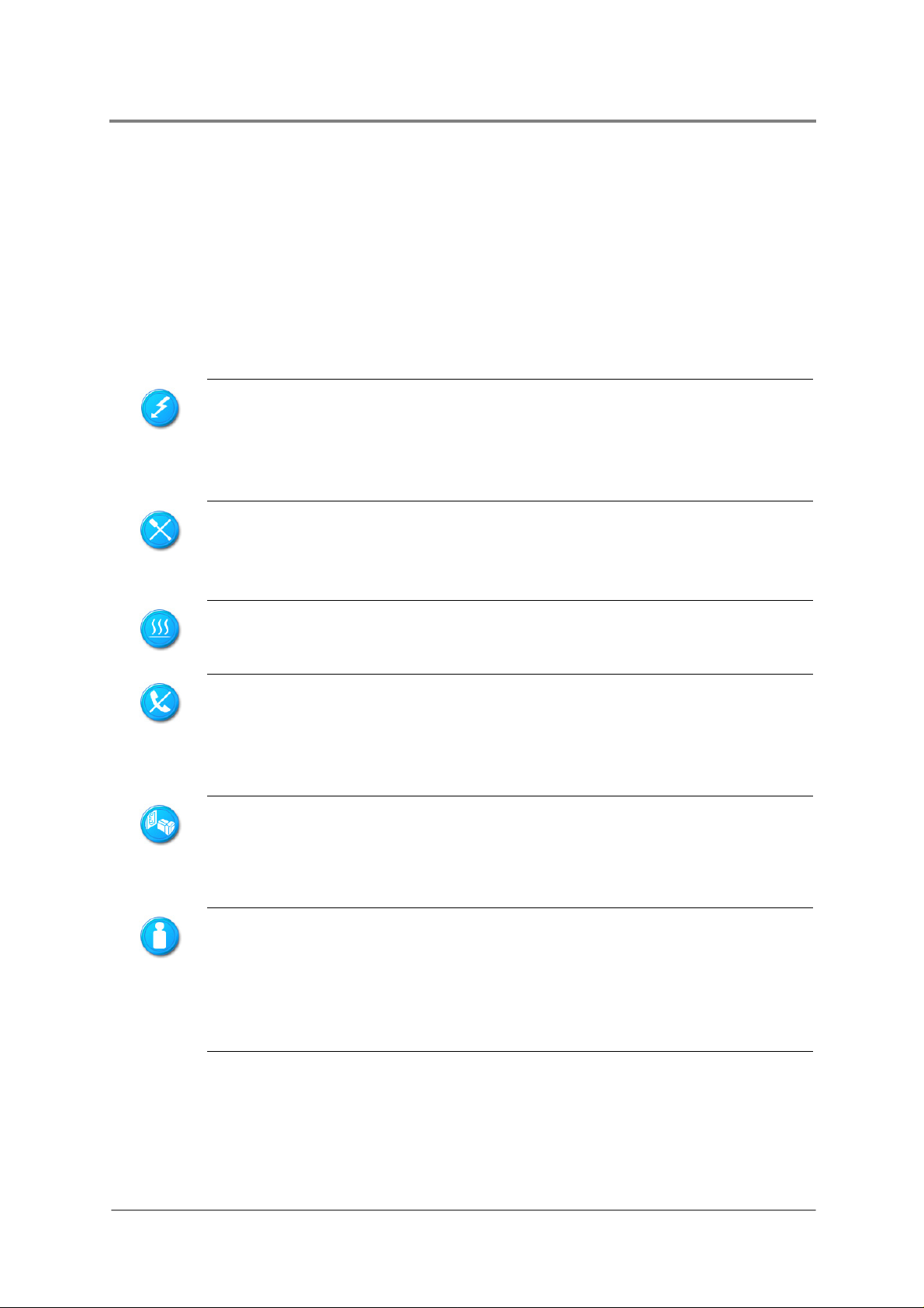
Indicates the potential hazard of energy circuits or electric shock. To reduce
the risk of injury from electric hazards, do not open this enclosure.
Warning:
indicates the presence of electric shock hazards. The enclosed area contains
no operator serviceable parts.
Indicates the potential hazard of electric shock. The enclosed area conta ins no
user of field serviceable parts. Do not open for any reason.
Warning:
this enclosure.
Indicates the presence of a hot surface or hot component.
Warning:
to cool before touching it.
Any RJ45 receptacle marked with this symbol indicates a network interface
connection.
Warning
equipment, do not plug telephone or telecommunications connectors into this
receptacle.
Any surface or area of the equipment marked with this symbol
To reduce the risk of injury from electric shock hazards, do not open
To reduce the risk of injury from a hot component, allow the surface
: To reduce the risk of electric shock, fire, or damage to the
Weight in kg
Weight in lb
1230B0033901
This symbol, on power supplies or systems, indicates that the equipment is
supplied by multiple sources of power.
Warning
: To reduce the risk of injury from electric shock, remove all power
cords to completely disconnect power from the system.
This symbol indicates that the component exceeds the recommended weight
for one individual to handle safely.
Warning: To reduce the risk of personal injury or damage to the equipment,
observe local occupational health and safety requirements and guidelines
for manual material handling.
ii
Page 11
About This Manual
Safety Precautions
Observe the following safety precautions when you are connecting or disconnecting any
device.
Regarding the standards of workstation regulations, do not place the server in the visual
field of the user, because of the glossy front of the case.
The product is non-consumer product and for profession technical person used only.
Operation Safety
Any operation on this server must be conducted by certified or experienced engineers.
Before operating your server, carefully read all the manuals included with the server
package.
Before using the server, make sure that all cables are correctly connected and power
cables are not damaged. If any damage is detected, contact your dealer as soon as
possible.
To avoid short circuits, keep paper clips, screws, and staples away from connectors,
slots, sockets and circuitry.
Before opening the chassis panels, make sure all power cables are unplugged.
Avoid dust, humidity, and extreme temperatures; place the server on a stable surface.
If the power supply is broken, do not try to fix it by yourself. Contact an authorized
dealer.
It is recommended that you wear gloves when assembling or disassembling the server
to protect from cuts and scrapes.
When the server is powered on, heat sinks and the surfaces of certain IC devices may
be hot. Do not touch them. Check whether the fans are functioning properly.
Electrical Safety
1230B0033901
Before installing or removing signal cables, ensure that the power cables for the system
unit and all attached devices are unplugged.
To prevent electric shock hazard, disconnect the power cable from the electrical outlet
before relocating the system.
When adding or removing any additional device to or from the system, ensure that the
power cables for those devices are unplugged before the signal cables are connected.
If possible, disconnect all power cables from the existing system before you add a
device.
iii
Page 12
About This Manual
Use one hand, when possible, to connect or disconnect signal cables to prevent a
possible shock from touching two surfaces with different electrical potentials.
This product is equipped with a three-wire power cable and plug for user safety. Use the
power cable with a properly grounded electrical outlet to avoid electric shock.
Boards, adapters, and disk drives are sensitive to static electricity discharge. These devices
are wrapped in antistatic bags to prevent this damage. Take the following precautions:
If you have an antistatic wrist strap available, use it while handling the device.
Do not remove the device from the antistatic bag until you are ready to install the device
in the system unit.
With the device still in its antistatic bag, touch it to a metal frame of the system.
Grasp cards and boards by the edges. Hold drives by the frame. Avoid touching the
solder joints or pins.
If you need to lay the device down while it is out of the antistatic bag, lay it on the
antistatic bag. Before picking it up again, touch the antistatic bag and the met al frame of
the system unit at the same time.
Handle the devices carefully to prevent permanent damage.
Battery Replacement Safety
This server is provided with an internal Lithium battery or battery pack. There is a danger of
explosion and risk of personal injury if the battery is incorrectly replaced or mistreated.
For more information about battery replacement or proper disposal, contact an authorized
reseller or your authorized service provider.
This server contains an internal Lithium Manganese Dioxide, or a Vanadium Pentoxide, or an
alkaline battery pack. There is risk of fire and burns if the battery p ack is n ot handled pr operly.
To reduce the risk of personal injury:
Do not attempt to recharge the battery.
Do not expose to temperatures higher than 70°C.
Do not disassemble, crush, puncture, shorten external contacts, or dispose in fire or
water.
Replace only with the spare parts designated for this product.
Batteries should not be littered along with the general household waste. Please use the public
collection system or return them to the supplier.
1230B0033901
iv
Page 13
Laser Peripherals or Devices Safety
To avoid risk of radiation exposure and/or personal injury:
Do not open the enclosure of any laser peripheral or device.
Laser peripherals or devices are not user serviceable.
Return to manufacturer for servicing.
Intended Application Uses
About This Manual
This product was evaluated as Information Technology Equipment (ITE), which may be
installed in offices, schools, computer rooms, and similar commercial type locations. The
suitability of this product for other product categories and environments (such as medical,
industrial, residential, alarm systems, and test equipment), other than an ITE application, may
require further evaluation.
Site Selection
The system is designed to operate in a typical office environment. Choose a site that is:
Clean, dry, and free of airborne particles (other than normal room dust).
Well-ventilated and away from sources of heat including direct sunlight and radiators.
Away from sources of vibration or physical shock.
Isolated from strong electromagnetic fields produced by electrical devices.
In regions that are susceptible to electrical storms, we recommend you plug your
system into a surge suppresser and disconnect telecommunication lines to your modem
during an electrical storm.
Provided with a properly grounded wall outlet.
Provided with sufficient space to access the power supply cord(s), because they serve
as the product's main power.
Mechanical Loading – Mounting of the equipment in the rack should be such that a
hazardous condition is not achieved due to uneven mechanical loading.
Tools Required
A cross scre wdriver or a flat screwdriver is needed to inst all or remove the component s in the
server.
1230B0033901
v
Page 14

About This Manual
Regulatory and Integration Information
Regulatory Compliance Identification Numbers
For the purpose of regulatory compliance certifications and identification, this server is
assigned a serial number. This server serial number can be found on the product label, along
with the required approval markings and information. When requesting certification
information for this product, always refer to this serial number. This serial number should not
be confused with the marketing name or model number.
Product Regulatory Compliance
Product Safety Compliance
This server complies with the following safety requirements:
Table i Product Safety Requirements
IEC 60950-1 Safety of Information Technology Equipment
EN 60950-1 Safety of Information Technology Equipment Including Electrical Business
Equipment, European Committee for Electrotechnical Standardization
(CENELEC)
UL 60950-1 Safety of Information Technology Equipment
UL 94 Tests for Flammability of Plastic Materials for Parts in Devices &
Appliances
GB4943 Safety of Information Technology Equipment
Worldwide Safety approvals can be supplied according to the requirements from Marketing or
Customer.
Product EMC Compliance
This product has been tested and verified to comply with the following electromagnetic
compatibility (EMC) regulations.
Communications Commission Notice
Part 15 of the Federal Communications Commission (FCC) Rules and Regulations has
established Radio Frequency (RF) emission limits to provide an interference-free radio
frequency spectrum. Many electronic devices, including computers, generate RF energy
incidental to their intended function and are, therefore, covered by these rules. These rules
place computers and related peripheral devices into two classes, A and B, depending upon
their intended installation. Class A devices are those that may reasonably be expected to be
installed in a business or commercial environment. Class B devices are those that may
1230B0033901
vi
Page 15

About This Manual
reasonably be expected to be installed in a residential environment (for example, personal
computers). The FCC requires devices in both classes to bear a label indicating the
interference potential of the device, as well as additional operating instructions for the user.
The rating label on the device shows which class (A or B) the equipment falls into. Class A
devices do not have an FCC logo or FCC ID on the label. Class B devices have an FCC logo
or FCC ID on the label. Once the class of the device is determined, refer to the following
corresponding statement.
Class A Equipment
This equipment has been tested and found to comply with the limits for a Class A digital
device, pursuant to Part 15 of the FCC Rules. These limits are designed to provide
reasonable protection against harmful interference when the equipment is operated in a
commercial environment. This equipment generates, uses, and can radiate radio frequency
energy and, if not installed and used in accordance with the instructions, may cause harmful
interference to radio communications. Operation of this equipment in a residential area is
likely to cause harmful interference, in which case the user will be required to correct the
interference at personal expense.
Declaration of Conformity for Products Marked with the FCC Logo—United States Only
This device complies with Part 15 of the FCC Rules Operation and is subject to the following
two conditions: (1) this device may not cause harmful interference, and (2) this device must
accept any interference received, including interference that may cause undesired operation.
For questions regarding your product, please contact the supplier.
To identify this product, refer to the Part, Series, or Model number found on the product.
European Union Notice
Products with the CE Marking comply with both the EMC Directive (89/336/EEC) and the
Low-Voltage Directive (73/23/EEC) issued by the Commission of the European Community.
Compliance with these directives implies conformity to the following European Norms (in
brackets are the equivalent international standards):
Table ii European Union EMC Requirements
EN55022 (CISPR 22) Electromagnetic Interference
EN55024 (IEC61000-4-2,3,4,5,6,8,11) Electromagnetic Immunity
EN61000-3-2 (IEC61000-3-2) Power Line Harmonics
EN61000-3-3 (IEC61000-3-3) Power Line Flicker
1230B0033901
vii
Page 16
Canadian Notice (Avis Canadien)
Class A Equipment
Japanese Notice
Taiwanese Notice
About This Manual
Power Cords
The power cord set included in the server meets the requirements for use in the country
where the server was purchased. If this server is to be used in another country, purchase a
power cord that is approved for use in that country.
The power cord must be rated for the product and for the voltage and current marked on the
product's electrical ratings label. The voltage and current rating of the cord should be greater
than the voltage and current rating marked on the product. In addition, the cross-sectional
area of the wires must be a minimum of 1.00mm² or 18AWG, and the length of the cords must
be between 1.8m (6 feet) and 3.6m (12 feet). If you have questions about the type of power
cord to use, contact an authorized service provider.
Route power cords so that they will not be walked on or pinched by items placed upon or
against them. Pay particular attention to the plug, electrical outlet, and the point where the
cords exit from the product.
1230B0033901
viii
Page 17

Chapter 1
Introduction
Audience Assumptions
Manual Organization
Packing Checklist
Specifications
Product Features
System Overview
Page 18

Introduction
1 Introduction
1.1 Audience Assumptions
This manual assumes that you are a service technician or network administrator familiar with
computer hardware, data storage and network administration terminology and tasks.
1.2 Manual Organization
This manual introduces the chassis along with their hardware information, and how to replace
the hardware and connect the cables. This manual is generally organized as follows:
Table 1-1 Manual Introduction
Introduction
Motherboard
Hardware
Operations
Cable Connections
Appendix
General server introduction.
Motherboard introduction and the hardware operations of the
components on it.
The operation of the components on the chassis, such as power
supplies, system fans, HDD, backplane, riser card and daughter
card.
How to connect cables correctly.
China RoHS Regulations information.
1.3 Packing Checklist
Make sure you have all the components shipped with your system. If any item contained in
the package is damaged or missing, please contact your local dealer for replacement. In
addition, keep the box and packing materials for possible future use. The server is shipped
with the following:
Table 1-2 Packing Checklist
Chassis
HDDs
Power Cords
Cables
Screws
Driver&Document CD
1230B0033901
2U rack-mounted chassis
Twelve 3.5” SATA&SAS HDDs
1 or 2 power cords
SAS HDD cable, power supply cables, front panel cable,
power cords, system fan cables and so forth
Two thumbscrews for the motherboard
One Driver&Document CD
1-1
Page 19
1.4 Specifications
The table below is the technical specification for the server.
Table 1-3 Specifications
Introduction
Dimensions
Weight
Temperature
Humidity
Power
Current
Height: 8.75cm
Width: 43 .00cm
Length: 69.55cm
Min-weight: 6. 6 5 kg ± 5% (1 x HDD)
Max-weight: 31.5kg ± 5% (12 x HDDs)
Operating System: +10ºC~+35ºC
Non-operating System: -40ºC~+70ºC
Operating System: +20%~+80%
Non-operating System: +10%~+95%
100-120/200-240VAC input, 50/60Hz
8/4A
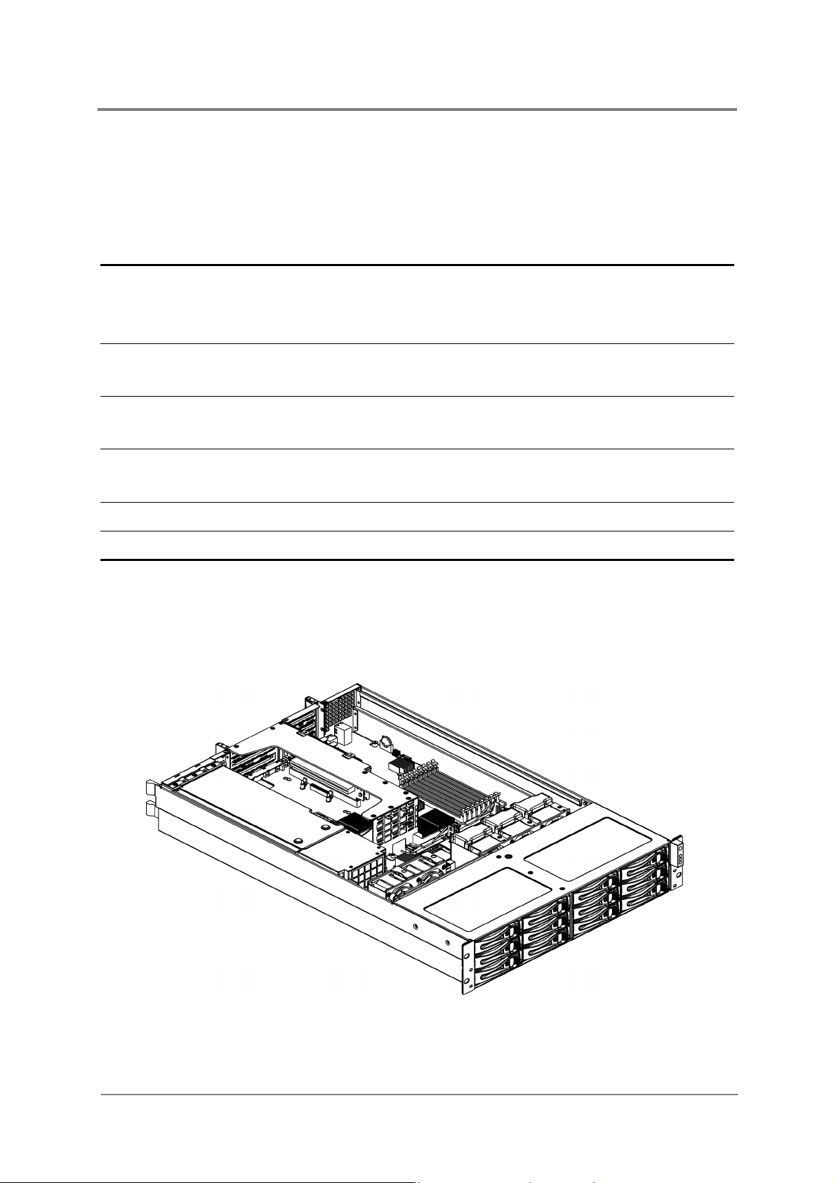
1.5 Product Features
This chapter describes the external features of this server. It includes specific sections that
identify these features and specifications. The whole picture of this server is shown below:
1230B0033901
Figure 1-1 Product Introduction
1-2
Page 20

Introduction
This server is configured for the motherboard that uses Intel® 5000P, Intel® 6321ESB and
®
Intel
82563EB chipset. It supports dual Intel® dual-core Xeon™ 5100 series processors with
667/1066/1333MHz FSB to accelerate even the most complicated server tasks. The following
highlights are the main features of the server. For additional information, refer to this user
manual.
Table 1-4 Product Features
Chassis
Power
Storage
Backplane
Processor
Chipset
System Memory
Onboard LAN
2U rack-mounted chassis.
Support one 700W power supply or 1+1 redundant power
supplies equipped with universal AC input that includes PFC
and SSI compliant output cables.
Twelve hot-pluggable 3.5” HDDs
SATA&SAS backplane with expander chip for twelve 3.5”
HDDs
Intel
Hyper-Threading Technology Support
Located on LGA 771-pin socket
Intel
Intel
Intel
Eight 240-pin DIMM vertical sockets
Supports up to 16GB of fully-buffered DDR2 667MHz
Dual Gigabit Ethernet RJ45 ports
Chip from Intel
®
dual-core Xeon™ 5100 series
®
5000P
®
6321ESB
®
82563EB
®
6321ESB and Intel® 82563EB
Onboard VGA
Integrated Super
I/O
Expansion Slot
Daughter Card
1230B0033901
Embedded in ServerEngines Pilot Chip
2.25MB Display Memory Embedded on Chip and enable to
share system memory
PCI-E x1 Lane
Winbond W83627HG-AW controller
Supports one fast UART 16550 serial port, one PS/2
Keyboard Port, and one PS/2 Mouse Port
One PCI-X 100MHz and two PCI-E x8 expansion slots with x4
speed
Two PCI-E x8 expansion slots with x4 speed
SAS RAID daughter card with two channels
1-3
Page 21
1.6 System Overview
1.6.1 Server Chassis Layout
Introduction
1230B0033901
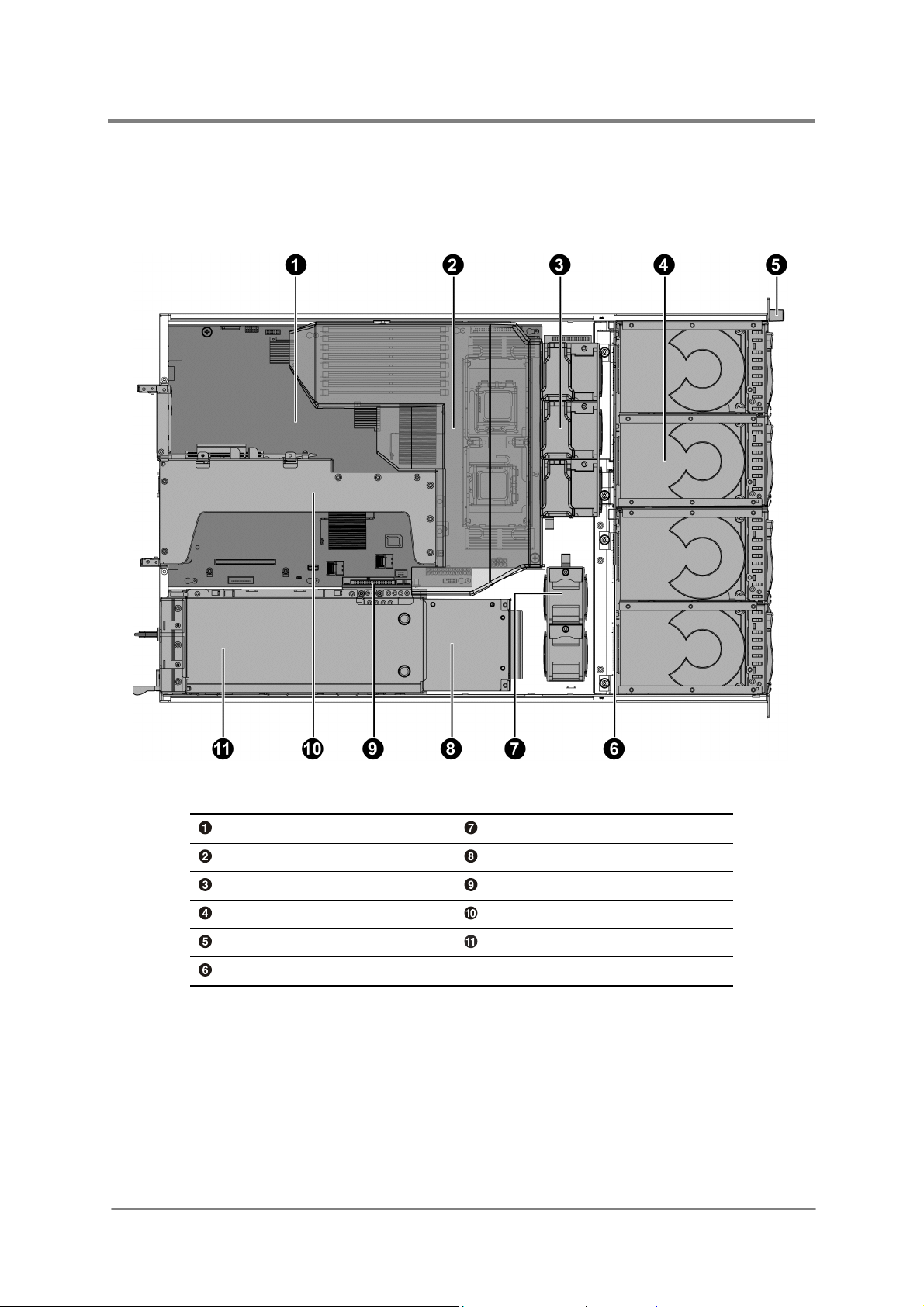
Figure 1-2 Server Chassis Layout
Motherboard System Fan (2)
Fan Duct Power Distribution Board
System Fan (1) IDE Converter Board
HDD Bays Riser Card Assembly
Front Panel Power Supply
SATA&SAS Backplane
1-4
Page 22

Introduction
1.6.2 Front View
The front view of this 2U server allows easy access to HDDs. In addition, the front panel with
buttons and system LEDs is located on the front. Please refer to the front view as follows:
Figure 1-3 Front View
HDD 0 HDD 6
HDD 1 HDD 7
HDD 2 HDD 8
HDD 3 HDD 9
HDD 4 HDD 10
HDD 5 HDD 11
HDD Tray LEDs Front Panel
1.6.3 Back View
The server back view includes the connectors of the external system devices.
Figure 1-4 Back View
Dual NIC Connector (RJ45) Serial Port
Management Port (RJ45) SAS JBOD Connector (Optional)
PS/2 Keyboard Port Rear Dual USB Port
PS/2 Mouse Port AC Power Connector 1
D-sub VGA Port AC Power Connector 2
UID LED
1230B0033901
1-5
Page 23
Introduction
1.6.4 Buttons and System LED Information
This server is equipped with system LED indicators and buttons located on the front panel.
Front panel status LEDs allow constant monitoring of basic system functions while the server
is operating. These LEDs provide visual cues to the status of system fans, power supply, and
system health.
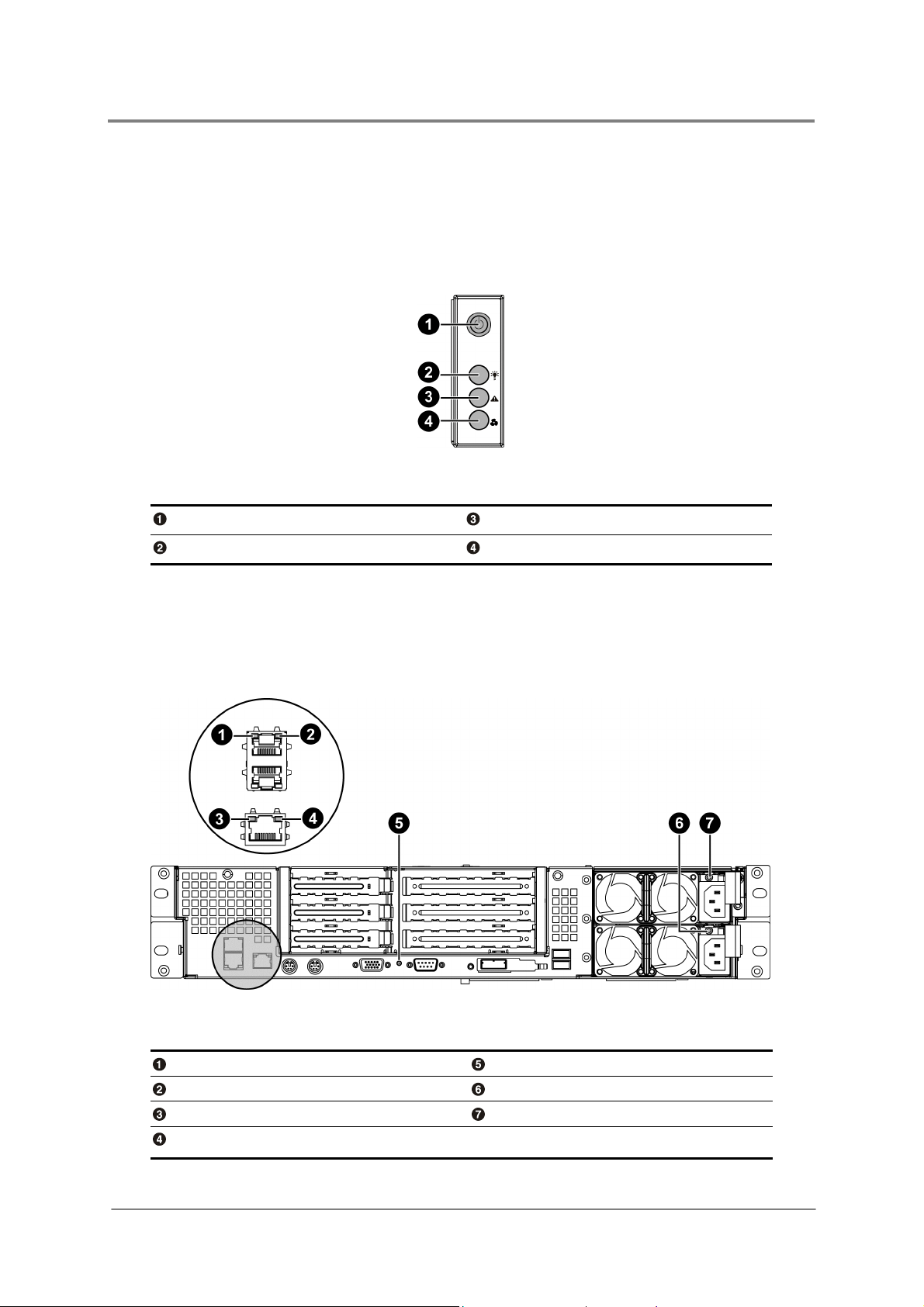
Figure 1-5 Front Panel
Power Button System Health LED
Power LED Fan Fail LED
The back view LED information displays details regarding the NIC LEDs, management port
LEDs, UID LED and AC power LEDs. Each NIC connector contains two LEDs that allow
monitoring of network activity and server identification.
NIC Link/Activity LED UID LED
NIC Speed LED AC Power LED 1
Link/Activity LED of Management Port AC Power LED 2
Speed LED of Management Port
1230B0033901
Figure 1-6 Back View LEDs
1-6
Page 24
The detailed LED information is shown below:
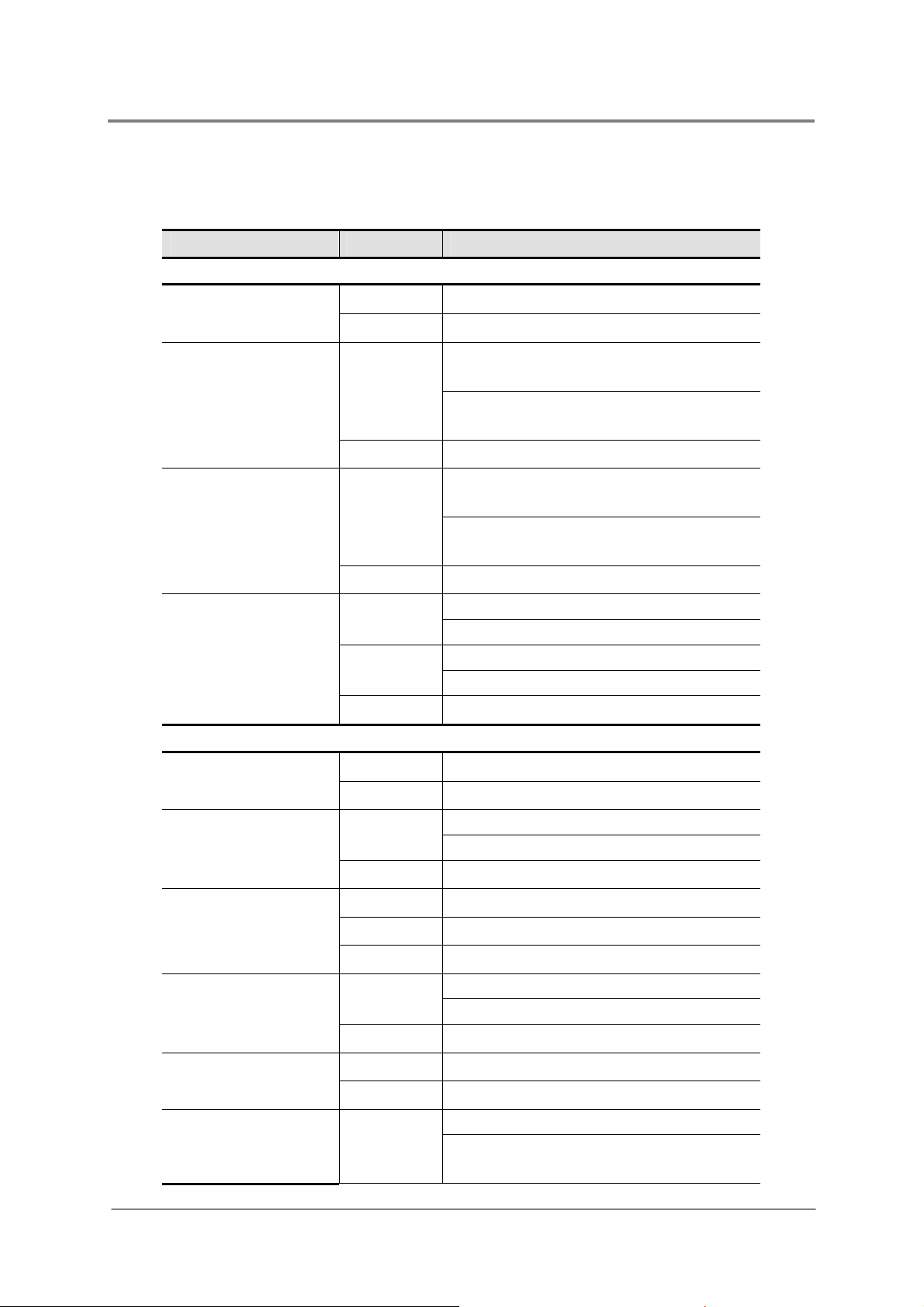
Table 1-5 LED Information
Type of LED Color Status
Front View LEDs
Blue
Power LED
−
Red
Fan Fail LED
−
Red
System Health LED
−
Introduction
On: Normal operating state
Off: System is in the off state
On: Critical Fault (Two or more fan
sensors fail)
Blinking: Non-critical Fault (One fan
sensor fails)
Off: Operation normal
On: Critical Fault (System needs to be
shut down and service)
Blinking: Non-critical Fault (System
Errors)
Off: Operation normal
HDD Tray LED
UID LED
NIC Link/Activity
LED
NIC Speed LED
Link/Activity LED of
Management Port
Blue
On: HDD present
Blinking: HDD data access
Red
On: HDD fault
Blinking: HDD rebuilding
−
Off: No HDD present
Back View LEDs
Blue
−
Green
On/Blinking: Chassis Identify
Off: Disabled
On: Linking On
Blinking: (At 1Hz rate) Access
−
Amber
Green
−
Green
Off: No Link
On: Linking at 1Gbps speed
On: Linking at 100Mbps speed
Off: Linking at 10Mbps speed
On: Linking on
Blinking: (At 1Hz rate ) Access
−
Off: No link
Speed LED of
Management Port
AC Power LED
1230B0033901
Green
−
Green
On: Linking at 100Mbps speed
Off: Linking at 10Mbps speed
On: Output ON and OK
Blinking:(At 1Hz) AC present/Only
5VSB on (PS off)
1-7
Page 25
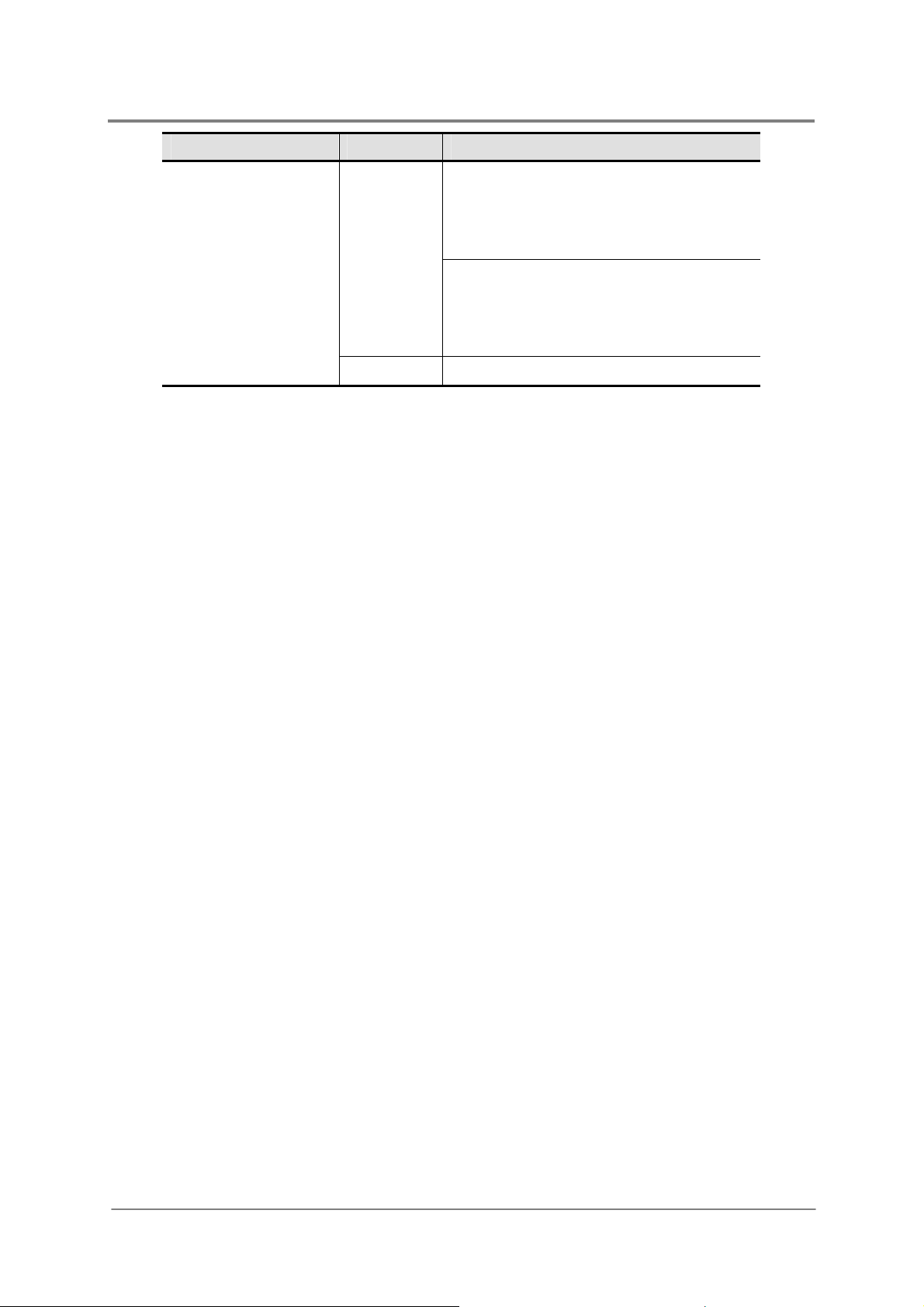
Type of LED Color Status
Amber
−
On: Power supply critical event causing
a shutdown; failure, OCP, OVP, Fan
Failed; No AC power to this PSU only
(for 1+1 configuration)
Blinking:(At 1Hz) Power supply warning
events where the power supply
continues to operate: high temperature,
high power, high current, slow fan
Off: No AC power to all power supplies
Introduction
1230B0033901
1-8
Page 26

Chapter 2
Motherboard
Motherboard Layout
Screw Holes
Processor
System Memory
System Configuration Jumper
Page 27

Motherboard
2 Motherboard
2.1 Motherboard Layout
The layout of the motherboard is shown below. Each connector and major component is
identified by the number.
Figure 2-1 Connectors and Component Locations
1230B0033901
2-1
Page 28

Motherboard
The words printed on the real motherboard to mark the processors are “CPU1”
and “CPU2”. Here just for consistency, the processors are marked with
“PROCESSOR1” and “PROCESSOR2” in the picture above.
Rear Dual USB Port (J35) DIMM6 Socket (J23)
Serial Port (J31) DIMM7 Socket (J24)
UID LED (CR16) DIMM8 Socket (J25)
D-sub VGA Port (J39) Fan Power/Fan Tach Connector (J99)
PS/2 Mouse Port (J15) Processor 1 (CPU1)
PS/2 Keyboard Port (J6) Processor 2 (CPU2)
Management Port (RJ45) (J59) Processor Power Connector (J28)
Dual NIC Connector (RJ45) (J14) LCM Connector (Optional) (J33)
PCI-E x8 Expansion Slot (J4) Main Power Connector (J5)
PCI-X 100MHz/PCI-E x16 Expansion Slot (J9) Internal USB Port for USB Floppy (J27)
Battery (B1) Front Panel USB Connector (J38)
System Configuration Jumper (J3) I2C (SMBus) Signal Connector for PSU (J46)
Front Panel VGA Connector (J13) Mini-SAS Connector 1 (J1)
I-button (U136) Front Panel IDE Connector (J7)
DIMM1 Socket (J18) Mini-SAS Connector 2 (J2)
DIMM2 Socket (J19) Chassis Intrusion Connector (J17)
DIMM3 Socket (J20) PCI-E Daughter Card Connector (J11)
DIMM4 Socket (J21) PCI-X Daughter Card Connector (J36)
DIMM5 Socket (J22) Floppy Connector (J26)
1230B0033901
2-2
Page 29

Motherboard
2.2 Screw Holes
The motherboard is designed with totally nine locking tab holes and two thumbscrews as the
picture shows.
Figure 2-2 Screws Placement
Thumbscrew
Locking Tab Hole
Do not overly tighten the thumbscrews. Doing so may damage the motherboard.
1230B0033901
2-3
Page 30

Motherboard
2.3 Processor
With two 771-pin LGA sockets, the system can be configured to either single or dual
processors system to connect to the Northbridge chipset through the Front Side Bus (FSB)
with Hyper Threading Technology.
The location of the processors on the motherboard is shown below:
Figure 2-3 Processor Location
Processor 1
Processor 2
You can install single or dual processors on the motherboard according to your own needs.
1. If SINGLE processor is intended, recommend that you install the processor on the
processor 1 socket, please refer to the figure above.
2. If install DUAL processors, use the same type of processor running at the same frequency.
1230B0033901
2-4
Page 31

Motherboard
Reminder
Before you remove or install heat sink, processor or heat sink socket, please follow the
steps below:
Step 1:
Make sure the server is not turned on or connected to the AC power. To power off
the server, see “3.1.1 Power Off”.
Step 2:
Step 3:
Remove the chassis cover. To remove the cover, see “3.2 Chassis Cover”.
Disconnect all necessary cable connections.
2.3.1 To remove the heat sink
Rotate to release the two levers.
Figure 2-4 Pulling up the Two Levers
Lift the heat sink up from the installed processor.
1230B0033901
Figure 2-5 Lifting the Heat Sink up
2-5
Page 32

2.3.2 To install the heat sink
Rotate and pull up the two levers.
Figure 2-6 Pulling up the Two Levers
Place the heat sink on top of the installed processor.
Motherboard
Figure 2-7 Placing the Heat Sink on Top of the Processor
Push down the levers to secure the heat sink on top of the processor.
Figure 2-8 Locking the Two Levers
Before you put the heat sink on top of the installed processor, please do not forget
to check if the grease is complete on bottom of the heat sink.
1230B0033901
2-6
Page 33

2.3.3 To remove the processor
Unlock the load lever and lift it up.
Open the load plate.
Figure 2-9 Opening the Load Plate
Lift the processor out of the socket.
Motherboard
Close the load plate.
Lock the load lever.
Figure 2-10 Lifting the Processor out of the Socket
Figure 2-11 Closing the Load Plate
1230B0033901
2-7
Page 34

Motherboard
Place the PnP cap onto the load plate.
Figure 2-12 Placing on the PnP Cap
2.3.4 To install the processor
Reverse the steps above to install the processor. However, when inserting the processor into
the socket, make sure that the golden corner on the processor is pointed toward the socket
as picture shows:
Figure 2-13 Pointing the Golden Corner toward the Socket
When the processor is in place, press it firmly on the socket while you push
down the socket lever to secure the processor. The lever clicks on the socket
indicating that it is locked.
The processor fits only in one orientation. Do not force the processor into the
socket to avoid bending the pins and damaging the processor. If the processor
does not fit completely, check its orientation or check for bent pins.
1230B0033901
2-8
Page 35

2.3.5 To remove the heat sink socket
Release the six screws from bottom of the motherboard.
Figure 2-14 Releasing the Screws
Lift the heat sink socket up from the motherboard.
Motherboard
Figure 2-15 Lifting up the Heat Sink Socket
2.3.6 To install the heat sink socket
Reverse the steps above to install the heat sink socket. However, when installing the heat
sink base socket into the bottom of the motherboard, make sure that the wider side of the
heat sink base socket is closer to the edge of the motherboard as the picture shown below:
1230B0033901
Figure 2-16 Installing the Heat Sink Base Socket
2-9
Page 36

2.4 System Memory
The location of the DIMM sockets on the motherboard is shown below:
Motherboard
Figure 2-17 System Memory Location
Reminder
Before you remove or install any DIMMs, please follow the steps below:
Step 1:
Step 2:
Step 3:
Make sure the server is not turned on or connected to the AC power. To power off
the server, see “3.1.1 Power Off”.
Remove the chassis cover. To remove the cover, see “3.2 Chassis Cover”.
Disconnect all the necessary cable connections.
1230B0033901
2-10
Page 37

Motherboard
2.4.1 To remove a DIMM
Unlock a DIMM socket by pressing the retaining clips outward. This action releases the
module and partially lifts it out of the socket.
Lift out the DIMM.
Figure 2-18 Lifting the DIMM out of the Socket
2.4.2 To install a DIMM
Unlock a DIMM socket by pressing the retaining clips outward.
Figure 2-19 Pressing the Retaining Clips Outward
Align the notch on the DIMM to the break on the socket. Carefully insert the DIMM into the
socket until the retaining clips snap back in place.
1230B0033901
Figure 2-20 Inserting the DIMM into the Socket
2-11
Page 38

DIMMs fit in only one direction. DO NOT force a DIMM into the socket to avoid
damaging the DIMM.
2.5 System Configuration Jumper
The location of system configuration jumper on the motherboard is shown below:
Motherboard
Figure 2-21 System Configuration Jumper
Table 2-1 System Configuration Jumper Function
Jumper Function Pin 1-2 Pin 2-3
A
B
C
D
E
F
The “*” in the table of system configuration jumper describes the default status
and the default state is not active state.
lear Password
Clear CMOS *Disable Enable
BIOS Boot Block Protect *Enable Disable
Clear RTC *Disable Enable
BIOS Recovery *Disable Enable
BMC Recovery *Disable Enable
*Disable Enable
1230B0033901
2-12
Page 39

Chapter 3
Hardware Operations
Before You Start
Chassis Cover
Motherboard
Power Distribution Board
Power Supply
IDE Converter Board
System Fans
SATA&SAS Backplane
SATA&SAS HDDs
Optional Riser Cards
Daughter Card
Fan Duct
Page 40

Hardware Operations
3 Hardware Operations
This chapter describes the hardware setup procedures that you have to perform when
replacing system components. It also gives detailed information on the internal components
and how to replace them. In addition, this server is also designed with the toolless feature,
which permits to remove or install the components without any tools. The locking tab,
retaining clip and so forth provide the convenient method to lock the components on the
server chassis. The toolless components are listed below:
Motherboard
Power Supply
System Fans
SATA&SAS Backplane
SATA&SAS HDDs
Optional Riser Cards
Daughter Card
The components shown in this chapter are mainly for your reference. Please take
the actual shipment as standard.
3.1 Before You Start
Take note of the following operations before you start to remove or install any internal
components.
3.1.1 Power Off
Before any replacement, you must power off the server completely. Follow the steps below to
power off the server completely.
To reduce the risk of injury from electric shock, remove the power cord to completely
disconnect power from the system.
Moving the Power On/Off switch to the Off position does not completely remove
power from the system. Some portions of the power supply and some internal
circuitry remain active. Disconnect all power cords from the server to completely
remove power from the system.
1230B0033901
3-1
Page 41

To press the button:
Press the power button
to toggle the server to hibernation. The power LED in blue
turns off.
Figure 3-1 Pressing the Power Button
To unplug the power cords:
First unplug the power cords from the AC outlet and then from the server.
Hardware Operations
Figure 3-2 Unplugging the Power Cords
3.2 Chassis Cover
The server is a 2U form factor designed for easy assembly and disassembly, making the
replacement of internal components very convenient.
Reminder
Before you remove or install the chassis cover, please follow the steps below:
Step 1:
Make sure the server is not turned on or connected to the AC power. To power off
the server, see “3.1.1 Power Off”.
Please remove the intruder switch from J17 to allow the system to continue
operating normally when the top cover of the chassis is opened.
1230B0033901
3-2
Page 42

To remove the chassis cover:
Loosen the screw on top of the cover.
Press the button as the arrow shows.
Meanwhile slide the cover horizontally to the back.
Figure 3-3 Removing the Top Cover
To install the chassis cover:
Slide the top cover horizontally to the front until it is closed.
Hardware Operations
Figure 3-4 Sliding the Top Cover to the Front
Tighten the chassis cover with the screw.
Figure 3-5 Tightening the Screw
This unit must be operated with the chassis top cover installed to ensure proper
cooling.
1230B0033901
3-3
Page 43

Hardware Operations
.
3.3 Motherboard
This section explains how to remove the motherboard from the chassis. For the operation of
main components on the motherboard.
The location of the motherboard on the server chassis is shown below:
Figure 3-6 Motherboard Location
Reminder
Before you remove or install the motherboard, please follow the steps below:
Step 1:
Step 2:
Step 3:
Step 4:
Make sure the server is not turned on or connected to the AC power. To power off
the server, see “3.1.1 Power Off”.
Remove the chassis cover. To remove the cover, see “3.2 Chassis Cover”.
Remove the riser card assembly. To remove the riser card assembly, see “3.10
Optional Riser Cards”.
Disconnect all necessary cable connections.
When installing the motherboard, make sure that you place it into the chassis
correctly.
The edge with the external ports goes to the back panel of the chassis.
When handling the motherboard, avoid touching any metal leads or connectors
1230B0033901
3-4
Page 44

Hardware Operations
To remove the motherboard:
1. Loosen the two thumbscrews
.
2. Release the motherboard from the chassis by unlocking the nine locking tabs
direction of the arrow and lift out the motherboard from the chassis.
along the
Figure 3-7 Removing the Motherboard
To install the motherboard:
Reverse the steps above to install the motherboard.
Do not overly tighten the thumbscrews. Doing so may damage the motherboard.
1230B0033901
3-5
Page 45

Hardware Operations
3.4 Power Distribution Board
All the power cables come out from the power distribution board.
The location of the power distribution board on the server chassis is shown below:
Figure 3-8 Power Distribution Board Location
Reminder
Before you remove or install the power distribution board, please follow the steps below:
Step 1:
Step 2:
Step 3:
Step 4:
To remove the power distribution board:
Push the release bar, and the power distribution board will be lifted automatically.
Pull out the power distribution board along the direction of the arrow.
Make sure the server is not turned on or connected to the AC power. To power off
the server, see “3.1.1 Power Off”.
Remove the chassis cover. To remove the cover, see “3.2 Chassis Cover”.
Remove the power supplies. To remove the power supplies, see “3.5 Power
Supplies”.
Disconnect all necessary cable connections.
1230B0033901
Figure 3-9 Removing the Power Distribution Board
3-6
Page 46

Hardware Operations
To install the power distribution board:
Place the power distribution board along the direction of the arrow.
Push it down firmly. Make sure that the power distribution board is connected to the power
supply connector on the power supply.
Figure 3-10 Installing the Power Distribution Board
3.5 Power Supplies
This server is designed with two 700W power supplies. When the server is equipped with
dual power supplies, the hot-swappable redundant function is provided. If one power supply
does not work, you can replace the failed power supply without powering off the server,
because the other one can take the place of the failed one.
The location of the power supplies on the server chassis is shown below:
Figure 3-11 Location of Power Supplies
Reminder
Before you remove or install the power supply, please follow the steps below:
Step 1:
1230B0033901
Disconnect all necessary cable connections.
3-7
Page 47

Hardware Operations
To remove the power supply:
Press the retaining clip on the right side of the power supply along the direction of the
arrow.
At the same time, pull out the power supply by using its handle. (The power supply takes
considerable force to remove.)
Figure 3-12 Removing the Power Supply
To install the power supply:
Insert the replacement power supply firmly into the bay until the retaining clip snaps back.
Connect the AC power to the replacement power supply.
1230B0033901
Figure 3-13 Installing the Power Supply
3-8
Page 48

Hardware Operations
3.6 IDE Converter Board
This server is designed with an IDE converter board, which connects the front panel cable
and the front IDE cable.
The IDE converter board is shown below:
Figure 3-14 IDE Converter Board
Front Panel Connector
IDE Flash Card Connector
Front Panel IDE Connector
The location of the IDE converter board on the server chassis is shown below:
Figure 3-15 IDE Converter Board Location
Reminder
Before you remove or install the IDE converter board, please follow the steps below:
Step 1:
Step 2:
Step 3:
1230B0033901
Make sure the server is not turned on or connected to the AC power. To power off
the server, see “3.1.1 Power Off”.
Remove the chassis cover. To remove the cover, see “3.2 Chassis Cover”.
Disconnect all necessary cable connections.
3-9
Page 49

Hardware Operations
Before removing the IDE converter board, the IDE flash card attached on it should be
removed first.
To remove the IDE flash card:
Lift up the IDE flash card to release it from the IDE converter board.
Figure 3-16 Removing the IDE Flash Card
To remove the IDE converter board:
Unscrew the IDE converter board.
Figure 3-17 Unscrewing the IDE Converter Board
Unscrew the three screws and remove the IDE converter board.
Figure 3-18 Removing the IDE Converter Board
To install the IDE converter board:
Reverse the steps above to install the IDE converter board.
1230B0033901
3-10
Page 50

Hardware Operations
3.7 System Fan Assemblies
This server contains two groups of hot-swapp able fans seated in th e system fan cage s, which
are located inside the chassis. These two groups of system fans respectively locate in system
fan cage (1) and system fan cage (2). The system fan cage (1) supports three sets of system
fans and the system fan cage (2) supports two system fans. These fans maintain the ideal
temperature for the motherboard, backplane and disk drives. If one fan fails, the speed of
other fans will increase. With the bad one replaced, the other fans may revert to the normal
speed.
The location of the system fan assemblies is shown below:
Figure 3-19 Location of System Fan Assemblies
System Fan Assembly (1)
System Fan Assembly (2)
Reminder
Before you remove or install the system fan and system fan cage, please follow the steps
below:
Step 1:
Step 2:
Remove the chassis cover. To remove the cover, see “3.2 Chassis Cover”.
Disconnect all necessary cable connections.
Before removing the system fans, please remove the system fan cage cable first.
1230B0033901
3-11
Page 51

To remove the system fan in the system fan cage (1):
Pull up the locking handle on the system fan.
Lift the system fan out of the system fan cage housing.
Figure 3-20 Lifting the System Fan out of the System Fan Cage (1)
To install the system fan in the system fan cage (1):
Reverse the steps above to install the system fans.
To remove the system fan in the system fan cage (2):
Lift the system fan out of the system fan cage housing.
Hardware Operations
Figure 3-21 Lifting the System Fan out of the System Fan Cage (2)
To install the system fan in the system fan cage (2):
Reverse the step above to install the system fans.
The system fan cage (1) and the system fan cage (2) share many similarities during the
removal and installation procedures. For your reference, the following is an example using
system fan cage (1).
1230B0033901
3-12
Page 52

Hardware Operations
To remove the system fan cage:
Lift the release tab.
Figure 3-22 Unlocking the System Fan Cage
Push the system fan cage along the direction of the arrow to unlock it from the chassis and
lift the system fan cage out of the chassis.
Figure 3-23 Removing the System Fan Cage
To install the system fan cage:
Position the system fan cage into the chassis by placing the holes of the system fan cage
onto the locking tabs on the bottom of the chassis, and push the system fan cage along the
direction of the arrow to lock it with the release tab.
Figure 3-24 Putting the System Fan Cage into the Chassis
1230B0033901
3-13
Page 53

Hardware Operations
3.8 SATA&SAS Backplane
The shape of SATA&SAS Backplane with expander chip for 12x3.5” HDDs is shown below:
Figure 3-25 Front & Back View of SATA&SAS Backplane
SATA&SAS HDD Connector 0 SATA&SAS HDD Connector 9
SATA&SAS HDD Connector 1 SATA&SAS HDD Connector 10
SATA&SAS HDD Connector 2 SATA&SAS HDD Connector 11
SATA&SAS HDD Connector 3 I2C (SMBus) Signal Connector
SATA&SAS HDD Connector 4 Backplane SATA&SAS Connector
SATA&SAS HDD Connector 5 3rd Party Connector
SATA&SAS HDD Connector 6 1x4pin Backplane Power Connector
SATA&SAS HDD Connector 7 2x3pin Backplane Power Connector
SATA&SAS HDD Connector 8
1230B0033901
3-14
Page 54

The location of the backplane is shown below:
Figure 3-26 Backplane Location
Reminder
Hardware Operations
Before you remove or install the SATA&SAS backplane, please follow the steps below:
Step 1:
Make sure the server is not turned on or connected to the AC power. To power off
the server, see “3.1.1 Power Off”.
Step 2:
Step 3:
Step 4:
Remove the chassis cover. To remove the cover, see “3.2 Chassis Cover”.
Remove the system fans. To remove the system fans, see “3.7 System Fans”.
Disconnect all necessary cable connections.
To remove the backplane:
Lift up the backplane assembly to remove it from the chassis.
Figure 3-27 Removing the Backplane Assembly
1230B0033901
3-15
Page 55

Hardware Operations
Press the release tab on the backplane bracket.
Remove the backplane along the direction of the arrow.
Figure 3-28 Removing the Backplane
To install the backplane:
Put the backplane at the backplane bracket with the locking tabs going through the holes
on the backplane, and push the backplane along the direction of the arrow until it is locked
by the locking tab.
Figure 3-29 Fixing the Backplane to the Backplane Bracket
Press the backplane assembly down with the locking tabs shown in the picture below
locked by the hole.
Figure 3-30 Installing the Backplane Assembly
1230B0033901
3-16
Page 56

Hardware Operations
3.9 SATA&SAS HDDs
The server can support twelve 3.5” SATA&SAS HDDs
The location of SATA&SAS HDD assemblies on the server chassis is shown below:
Figure 3-31 Location of HDD Assemblies
Take note of the drive tray orientation before sliding it out.
The tray will not fit back into the bay if inserted incorrectly.
The HDD requires replacement under the following condition:
The HDD tray LED is red. You have removed and reseated the HDD assembly, and the LED
remains red.
To remove the HDD:
Turn the lock on the lever counterclockwise to the location of unlocking symbol.
Slide the released button along the direction of the arrow, and the lever will be lifted
automatically.
1230B0033901
Figure 3-32 Releasing the Lever
3-17
Page 57

Slide the HDD assembly out of the HDD bay.
Figure 3-33 Sliding the HDD Assembly
To install the HDD:
Place the HDD to the HDD tray.
Hardware Operations
Figure 3-34 Placing the HDD to the HDD tray
Secure the HDD to the HDD tray with four screws as shown.
Figure 3-35 Securing HDD to the HDD Tray
1230B0033901
3-18
Page 58

Hardware Operations
Carefully insert the HDD assembly into the bay with the lever lifted until it completely
enters the bay.
Figure 3-36 Inserting the HDD Assembly
Push the lever back in place.
Turn the lock on the lever clockwise to secure the HDD.
Figure 3-37 Pushing the Lever Back in Place
Make sure that the HDD is connected to the HDD connector on the backplane.
3.10 Optional Riser Cards
The motherboard provides one 280-pin PCI-X 100MHz/PCI-E x8 expansion slot and one
PCI-E expansion slot. The PCI-X 100MHz/PCI-E x8 expansion slot can support one PCI-X
100MHz and two PCI-E x8 slots with x4 speed using the riser card. The PCI-E exp ansion slot
can support two PCI-E x8 slots with x4 speed using the riser card. The riser card comes with
the system package. The golden fingers of the riser card connect to the PCI slots on the
motherboard.
1230B0033901
3-19
Page 59

The PCI-X/PCI-E riser card is shown below:
Figure 3-38 PCI-X/PCI-E Riser Card
Golden Fingers
PCI-E x8 Expansion Slots with x4 Speed
PCI-X Expansion Slot
Hardware Operations
The PCI-E riser card is shown below:
Figure 3-39 PCI-E Riser Card
Golden Fingers
PCI-E x8 Expansion Slots with x4 Speed
The two riser cards share many similarities during the removal and installation procedures.
For your reference, the following is an example using the PCI-X/PCI-E riser card.
1230B0033901
3-20
Page 60

The location of riser card assembly is shown below.
Figure 3-40 Riser Card Assembly Location
Reminder
Hardware Operations
Before you remove or install the riser card, please follow the steps below:
Step 1:
Step 2:
Step 3:
Make sure the server is not turned on or connected to the AC power. To power off
the server, see “3.1.1 Power Off”.
Remove the chassis cover. To remove the cover, see “3.2 Chassis Cover”.
Disconnect all necessary cable connections.
To remove the riser card:
Pull the release clips along the direction of the arrow.
Lift the riser card assembly out of the chassis.
Figure 3-41 Lifting the Riser Card Assembly
1230B0033901
3-21
Page 61

Open the lock along the direction of the arrow.
Pull out the expansion card.
Install the slot cover.
Figure 3-42 Removing the Expansion Card
Press the locking tab.
Push the riser card along the direction of the arrow.
Hardware Operations
Figure 3-43 Releasing the Riser Card
Lift the riser card along the direction of the arrow.
Figure 3-44 Removing the Riser Card
To install the riser card:
Reverse the steps above to install the riser card assembly.
1230B0033901
3-22
Page 62

Hardware Operations
3.11 Daughter Card
This server provides SAS RAID daughter card with two channels. It is designed to provide
extra HDD storage capability. This section provides the location, removal and installation
steps of the daughter card. SAS RAID Daughter Card supports two SAS channels with
256MB embedded memory.
Figure 3-45 2CH SAS RAID Daughter Card
Channel B (CHB) (Port 4-7)
Channel A (CHA) (Port 0-3)
Table 3-1 2CH SAS RAID Daughter Card Information
Functional brief
RAID
Storage Interface
HDD Mode
Host Interface
LSI1078 SAS two channels daughter card
RAID 0, 1, 5, 10 and JBOD
HDD fault LED signal connector
SATAII/SAS
IESC 80-pin daughter card connector
PCI-E slot support
The location of SAS daughter card is shown below:
1230B0033901
Figure 3-46 SAS Daughter Card Assembly Location
3-23
Page 63

Hardware Operations
Reminder
Before you remove or install the daughter card, daughter-card latch and I-button, please
follow the steps below:
Step 1:
Make sure the server is not turned on or connected to the AC power. To power off
the server, see “3.1.1 Power Off”.
Step 2:
Step 3:
Remove the chassis cover. To remove the cover, see “3.2 Chassis Cover”.
Remove the riser card assembly. To remove the riser card assembly, see “3.10
Optional Riser Cards”.
Step 4:
Disconnect all necessary cable connections.
To remove the daughter card:
Push aside the release buttons while pulling the daughter card out of the pole.
At the same time, lift the daughter card out of the daughter card connector on the
motherboard.
Figure 3-47 Removing the Daughter Card Assembly
To install the daughter card:
Make the daughter card parallel to the motherboard surface and point the hole toward the
plastic pole.
Carefully insert the SAS daughter card until it completely fits the space.
Figure 3-48 Installing the Daughter Card Assembly
1230B0033901
3-24
Page 64

Hardware Operations
To connect the daughter card with the JBOD:
Connect on end of the SAS JBOD cable to the SATA&SAS connector on the daughter
card.
Connect the other end of the SAS JBOD cable to the SATA&SAS connector on the JBOD.
Figure 3-49 Connecting the SAS JBOD Cable
When installing the SAS RAID daughter card with two channels (LSI1078 SAS daughter card),
a daughter-card latch is necessary to fix it tightly. For the installation and removal procedure,
please see below.
To remove the daughter-card latch:
Push aside the release buttons.
At the same time, pull the daughter-card latch out of the pole.
Figure 3-50 Removing the Daughter-card Latch
1230B0033901
3-25
Page 65

Hardware Operations
To install the daughter-card latch:
Make the daughter-card latch parallel to the daughter card surface, point the hole toward the
plastic pole, and then carefully insert it.
Figure 3-51 Installing the Daughter-card Latch
When installing the SAS RAID daughter card with two channels (LSI1078 SAS daughter card),
an I-button is necessary to be installed. For the removal and installation procedure, please
refer to the information below.
The location of I-button is shown below:
Figure 3-52 I-button Location
To remove the I-button:
Push aside the two locking clips.
Lift the I-button out of the socket.
Figure 3-53 Removing the I-button
1230B0033901
3-26
Page 66

To install the I-button:
Put the I-button into the socket.
Figure 3-54 Installing the I-button
3.12 Fan Duct
The location of the fan duct is shown below:
Hardware Operations
Figure 3-55 Fan Duct Location
Reminder
Before you remove or install the fan duct, please follow the steps below:
Step 1:
Step 2:
Make sure the server is not turned on or connected to the AC power. To power off
the server, see “3.1.1 Power Off”.
Remove the chassis cover. To remove the cover, see “3.2 Chassis Cover”.
1230B0033901
3-27
Page 67

Hardware Operations
To remove the fan duct:
Lift the fan duct along the direction of the arrow shown in the picture below.
Figure 3-56 Removing the Fan Duct
To install the fan duct:
Reverse the step above to install the fan duct.
1230B0033901
3-28
Page 68

Chapter 4
Cable Connections
Connectors and Pin 1 Locations
Cable Connections
Power Supply
Power On
Page 69

Cable Connections
4 Cable Connections
This chapter provides the details of all necessary cables connection for 2U server.
4.1 Connectors and Pin 1 Locations
The figure below shows the different locations of necessary connectors and their pin 1
locations, which can make you easily connect the cables.
1230B0033901
Figure 4-1 Locations of Connectors and Pin 1
4-1
Page 70

Cable Connections
4.2 Cable Connections
You can get a clear picture on how to connect the cables from the figures below.
Before connecting cables you must make sure there are no bent pins existing because it
affects signal transmission. With the pin 1 location and foolproof feature, you can link these
cables correctly and conveniently. There are two ways for you to judge how to connect the
cables:
1. When there is no foolproof feature on this connector, you should connect the red margin of
the cable to the pin 1 location on the connector.
2. When there is a foolproof feature on the connector, you can connect the cable according to
the foolproof feature.
This section contains figures showing cable locations and descriptions of the connection
procedures. This section shows all the cable connections associated with the server.
4.2.1 JBOD Cable
This server is designed with SAS JBOD as the picture shown below. These connectors are
used to connect to the daughter card and external device. The detailed connection method is
listed as follows:
For SAS JBOD, is used to connect to the external devices; is used to connect to
the daughter cards.
Figure 4-2 JBOD Introduction
1230B0033901
For the detailed information about the connector on the backplane as the
picture shown below, please refer to “3.8 SATA&SAS Backplane”.
For the description of daughter card, please refer to “3.11 Daughter Card.
4-2
Page 71

Cable Connections
4.2.2 Front Panel Cable
Front Panel IDE Cable
Connect one end of the front panel IDE cable to the front panel IDE connector on the
motherboard.
Connect the other end of the front panel IDE cable to the corresponding connectors on the
IDE converter board.
Figure 4-3 Connecting the Front Panel IDE Cable
Front Panel Cable
Since the specifications of each button and LED are different, they must be installed in the
defined position. When connecting the front panel cable, please follow the cable connection
layout below:
1230B0033901
Figure 4-4 Front Panel Cable Connection Layout
4-3
Page 72

Cable Connections
Connect one end of the front panel cable to the front panel connector on the front panel.
Connect the other end of the front panel cable to the corresponding connectors on the IDE
converter board.
Figure 4-5 Connecting the Front Panel Cable
To remove the front panel cable
Remove the two screws on the side of the chassis.
Figure 4-6 Releasing the Screws
Pull out the front panel assembly.
Release the locking tab along the direction of the arrow.
Remove the front panel assembly along the direction of the arrow.
1230B0033901
Figure 4-7 Removing the Front Panel
4-4
Page 73

Pull the clips outward to release the buttons.
Figure 4-8 Releasing the Buttons
Pull out the front panel cable.
Cable Connections
Figure 4-9 Pulling out the Front Panel Cable
To install the front panel cable
Reverse the steps above to install the front panel cable.
1230B0033901
4-5
Page 74

Cable Connections
4.2.3 Power Cables
Main Power Cable
Connect the 24-pin main power cable from the power supply to the main power connector on
the motherboard.
Figure 4-10 Connecting the Main Power Cable
Processor Power Cable
Connect the 8-pin processor power cable from the power supply to the processor power
connector on the motherboard.
Figure 4-11 Connecting the Processor Power Cable
1230B0033901
4-6
Page 75

Cable Connections
4.2.4 SATA&SAS HDD Cable
Connect one end of the SATA&SAS HDD cable to the SATA&SAS connector on the SAS
daughter card.
Connect the other end of the SATA&SAS HDD cable to the backplane SATA&SAS
connector on the backplane.
Figure 4-12 Connecting the SATA&SAS HDD Cable
4.2.5 Backplane Power Cables
6-pin Backplane Power Cable
Connect the 6-pin backplane power cable from the power supply to the power connector on
the backplane.
1230B0033901
Figure 4-13 Connecting the 6-pin Backplane Power Cable
4-7
Page 76

Cable Connections
4-pin Backplane Power Cable
Connect the 4-pin backplane power cable from the power supply to the power connector on
the backplane.
Figure 4-14 Connecting the 4-pin Backplane Power Cable
4.2.6 Power Supply I2C Cable
Connect the 5-pin power supply I2C cable from the power supply to the power supply I2C
connector on the motherboard.
Figure 4-15 Connecting the Power Supply I
2
C Cable
1230B0033901
4-8
Page 77

Cable Connections
4.2.7 System Fan Cables
System Fan Cable
For the connectors of system fan cage (1) and system fan cage (2), please refer to the figure
below.
Figure 4-16 System Fan Connector Locations
Connector of System Fan Cage (2)
Connector of System Fan Cage (1)
Connect one end of the fan cable to the fan connector on the system fan cage (2).
Connect the other end of the fan cable to the fan connector on the system fan cage (1).
1230B0033901
Figure 4-17 Connecting the System Fan Cable
4-9
Page 78

Cable Connections
System Fan Power/Fan Tach Cable
Connect one end of the fan power/fan tach cable to the fan power connector on the
motherboard.
Connect the other end of the fan power/fan tach cable to the fan power connector on the
system fan cage (1).
Connect connector A to connector B.
Connect connector C to the power connector from the power supply.
1230B0033901
Figure 4-18 Connecting the System Fan Power/Fan Tach Cable
4-10
Page 79

Cable Connections
4.2.8 Chassis Intrusion Cable
Connect one end of the chassis intrusion cable to the chassis intrusion connector on the
motherboard.
Connect the other end of the chassis cable to power supply cage.
Figure 4-19 Connecting the Chassis Intrusion Cable
4.3 Power Supply
The system comes with two 700W power supplies with universal AC input that includes PFC
and SSI-compliant output cables and connectors.
Figure 4-20 Power Supply Assembly
Main Power Connector
P1
Processor Power Connector
P2
Power Supply I
P3
1230B0033901
2
C Connector
6-pin Backplane Power Connector
P4
4-pin Backplane Power Connector
P5
4-11
Page 80

Cable Connections
4.4 Power On
Before you turn on the server, make sure that you have completed the basic system
connections. Follow these steps when starting the server.
Step 1: Monitor Connection
Connect a monitor by plugging a video cable to the VGA port at the back of the server.
Step 2: PS/2 Keyboard Connection
Plug the keyboard cable into the keyboard port on the back of the server.
Step 3: PS/2 Mouse Connection
Plug the mouse cable into the mouse port on the back of the server.
Step 4: Power Connection
Connect a power cord to the AC power connector at the back of the server, and then plug the
power cord to a grounded wall socket.
Step 5: Peripheral Connection
Connect a cable to the peripheral connector if required.
There is only one way to plug in all the connectors.
Figure 4-21 Connecting Cables for Powering On
PS/2 Keyboard Port AC Power Connector 1
PS/2 Mouse Port AC Power Connector 2
D-sub VGA Port
1230B0033901
4-12
Page 81

Step 6: Power on
Press the power button
LED
turns blue.
Cable Connections
on the front panel to toggle the server to power on. The power
Figure 4-22 Powering On
Power Button
Power LED
1230B0033901
4-13
Page 82

A
ppendix
China RoHS Regulations
Page 83

Appendix China RoHS Regulations
Appendix
1230B0033901
Appendix Figure I China RoHS Regulations
I
 Loading...