

Regency Panorama P36E Installation Manual
P36E Zero Clearance
Direct Vent Gas Fireplace
MODELS: P36E-NG4 Natural Gas P36E-LP4 Propane
Owners & Installation Manual
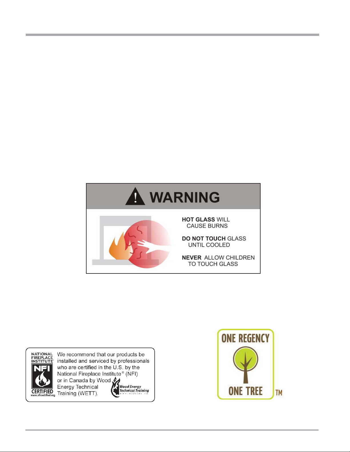
WARNING:
If the infor mation in these in structi ons are not followed exact ly, a fi re
or explosion may result c ausing propert y damage, per sonal injury or
loss of life.
FOR YOUR SAFETY
Do not store or use gasoline or other fl ammable vapors and liquids in the
vicinity of this or any other appliance.
Installation and service must be performed by a qualifi ed installer, service
agency or the gas supplier.
FOR YOUR SAFETY
Tested by:
Installer: Please complete the details on the back cover
and leave this manual with the homeowner.
Homeowner: Please keep these instructions for future reference.
918-852a
FPI FIREPLACE PRODUCTS INTERNATIONAL LTD. 6988 Venture St., Delta, BC Canada, V4G 1H4
What to do if you smell gas:
Do not try to light any appliance
Do not touch any electrical switch: do not
use any phone in your building.
Immediat ely call your gas sup plier from
a neighbour's phone. Follow the gas
supplier's instructions.
If you cannot reach your gas supplier, call
the fi re department.
03/23/10
To the New Owner:
Congratulations!
You are the owner of a state-of-the-art Gas Fireplace by FPI FIREPLACE PRODUCTS
INTERNATIONAL LTD. The P36E has been designed to provide you with all the warmth and
charm of a wood fi replace at the fl ick of a switch. The model P36E has been approved by W arnock
Hersey for both safety and effi ciency. As it also bears our own mark, it promises to provide you
with economy, comfort and security for many trouble free years to follow. Please take a moment
now to acquaint yourself with these instructions and the many features of your FPI Fireplace.
2
P36E-4 Zero Clearance Direct Vent Gas Fireplace
INFORMATION FOR MOBILE/MANUFACTURED HOMES AFTER FIRST SALE
This FPI product has been tested and listed by Warnock Hersey as a Vented Gas Fireplace Heater to the following standards: CAN/CGA-2.17M91, and ANSI Z21.88-2009/CSA 2.33-2009.
This Direct Vent System Appliance must be installed in accordance with the manufacturer's installation instructions and the Manufactured Home
Construction and Safety Standard, Title 24 CFR, Part 3280, or the current Standard of Fire Safety Criteria for Manufactured Home Installations,
Sites, and Communities ANSI/NFPA 501A, and with CAN/CSA Z240-MH Mobile Home Standard in Canada.
This appliance installation must comply with the manufacturer's installation instructions and local codes, if any. In the absence of local codes follow
the current National Fuel Gas Code, ANSI Z223.1 and the current National Electrical Code ANSI/NFPA 70 in the U.S.A., and the current CAN/CGA
B149 Gas Installation Code and the current Canadian Electrical Code CSA C22.1 in Canada.
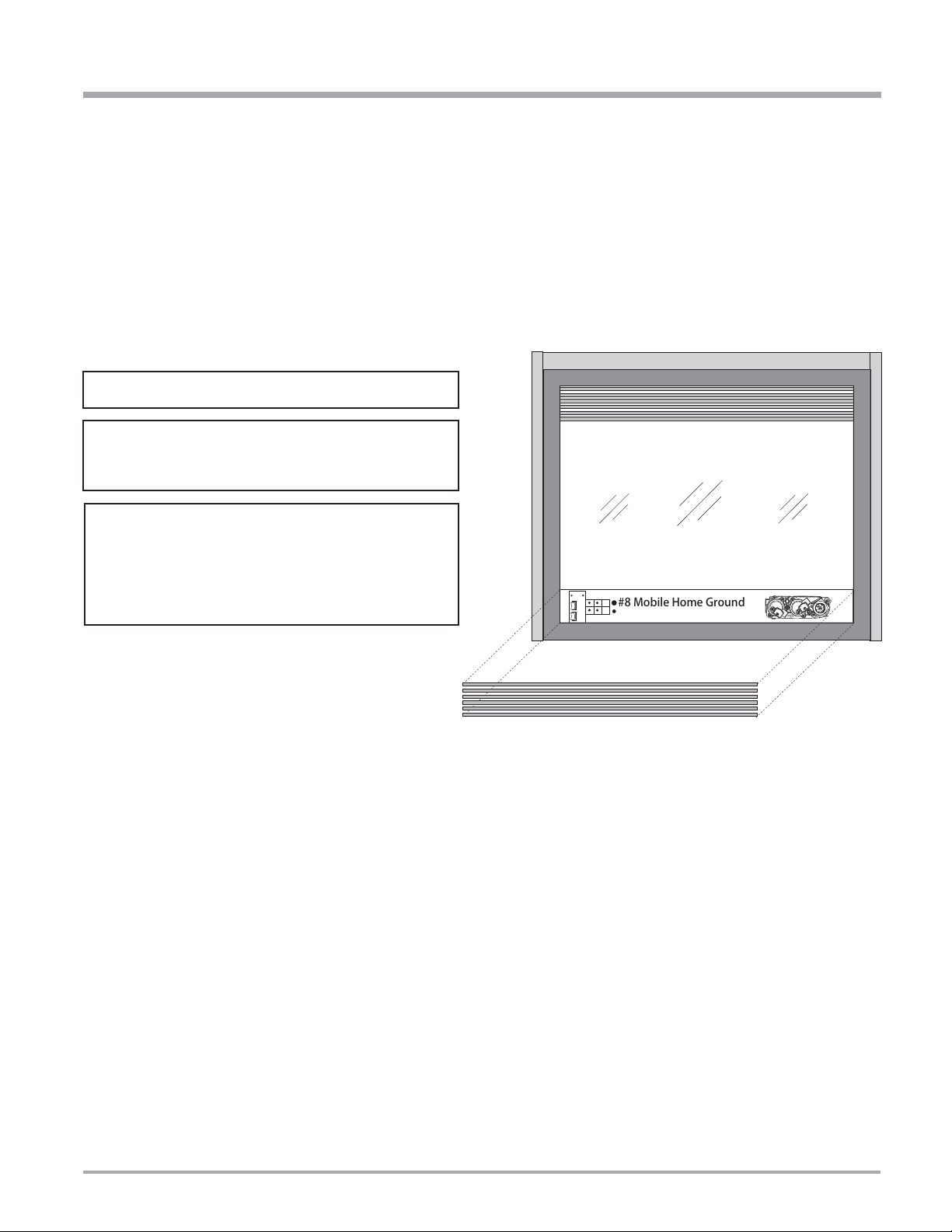
Nailing Strip
This FPI Mobile/Manufactured Home Listed appliance comes
factory equipped with a means to secure the unit.
This FPI Mobile/Manufactured Home listed appliance comes
equipped with a dedicated #8 ground lug to which an 18
gauge copper wire from the steel chassis ground must be
attached.
This appliance may only be installed in an aftermarket
permanently located, manufactured (mobile) home,
where not prohibited by local codes.
This appliance is only use with the type of gas indicated
on the rating plate. This appliance is not convertible for
use with other gases, unless a certifi ed kit is used.
Nailing Strip
Nailing Strip
#8 Mobile Home Ground
P36E-4 Zero Clearance Direct Vent Gas Fireplace 3

TABLE OF CONTENTS
SAFETY LABEL
Safety Label...................................................................6
REQUIREMENTS
MA Code - CO Detector.................................................7
(for the State of Massachusetts only) ............................7
DIMENSIONS
Unit Dimensions ............................................................8
Hampton Faceplate Dimensions ...................................8
INSTALLATION
Important Message ......................................................9
Before You Start ............................................................9
General Safety Information............................................9
Installation Checklist ......................................................9
Locating Your Gas Fireplace .......................................10
Manufactured Mobile Home Additional Requirements 10
Heatwave Duct System ...............................................10
Heat Release kit ..........................................................10
Clearances ..................................................................11
Regency® Clearances ..........................................12
Tripoli Screen
Door Clearances ..................................................12
Hampton® Clearances .........................................12
Regency® Series Combustible Mantel Clearances .....13
Hampton® Combustible Mantel Clearances ...............14
Mantel Leg Clearances................................................15
Framing and Finishing .................................................16
Regency® Tripoli Screen Door Series Framing Note ...17
Unit Assembly Prior to Installation ...............................18
Top Standoff Assembly ........................................18
Top Facing Support and Side Nailing Strips ........18
Venting Introduction .....................................................18
Exterior Vent Termination Locations ............................19
Venting.........................................................................20
Direct Vent System (Flex) ..................................20
4” x 6-5/8” Rigid Pipe Cross Reference Chart .............21
Rigid Pipe Venting Systems .................................23
Rigid Pipe Venting Arrangements ...............................24
Horizontal Terminations .......................................24
Vertical Terminations ...........................................27
Vertical Termination - Co-linear Flex System ...............29
Venting Arrangements - Vertical Termination ...............30
Direct Vent System (Flex) Installation Procedures ......33
Gas Line Installation ....................................................34
Pilot Adjustment ...........................................................35
886 S.I.T. Valve Description .........................................35
Gas Pipe Pressure Testing ..........................................35
High Elevation .............................................................35
Conversion from NG to LP .................................................. 36
Optional Brick Panels ..................................................36
Log Set Installation ......................................................38
Standard Flush Door ...................................................41
Optional Wall Thermostat ...........................................42
Optional Remote Control .............................................42
Optional Wall Switch ....................................................42
GT Remote Installation ................................................43
GTM Remote Installation .............................................44
GTMF Remote Installation...........................................46
Wiring Diagrams .........................................................48
Optional Fan Wiring Diagram .....................................49
OPERATING INSTRUCTIONS
Fan Installation (Optional) ...........................................50
Fan Removal ...............................................................50
Operating Instructions .................................................51
Lighting Procedure ......................................................51
Shutdown Procedure ...................................................51
First Fire ......................................................................51
Aeration Adjustment ....................................................51
Normal Operating Sounds Of Gas Appliances ............51
Copy of the Lighting Plate Instructions ........................51
NOTE: All installation instructions apply to
Regency® & Hampton® Series unless otherwise specifi ed.
4
P36E-4 Zero Clearance Direct Vent Gas Fireplace

TABLE OF CONTENTS
MAINTENANCE
Maintenance Instructions.............................................53
General Vent Maintenance ..........................................53
Gold-plated &Brass Louvers or Trim ...........................53
Log Replacement ........................................................53
Thermocouple..............................................................53
Glass Gasket ...............................................................53
Door Glass...................................................................53
Flush Glass Replacement ....................................53
Removing Valve ...........................................................54
Installing Valve .............................................................54
REGENCY® OPTIONS
Flush Trim ....................................................................55
Flush Louvers ..............................................................55
Double Screen Door ...................................................55
Bay Door......................................................................56
Bay Trim ......................................................................56
Bay Louvers.................................................................56
Finishing Trim ..............................................................57
Full Screen doors Installation ......................................58
Tripoli Screen Door ......................................................60
HAMPTON® OPTIONS
Hampton® Cast Faceplate ...........................................62
Hampton® Cast Grills ...................................................63
PARTS LIST
Main Assembly ............................................................64
Burner Assembly & Log Set.........................................65
Regency® Flush Front Accessories .............................66
Regency® Bay Front Assembly ....................................67
Hampton Cast
Faceplate & Grill Assembly..........................................68
WARRANTY
The Warranty: Limited Lifetime ....................................71
P36E-4 Zero Clearance Direct Vent Gas Fireplace 5
SAFETY LABEL
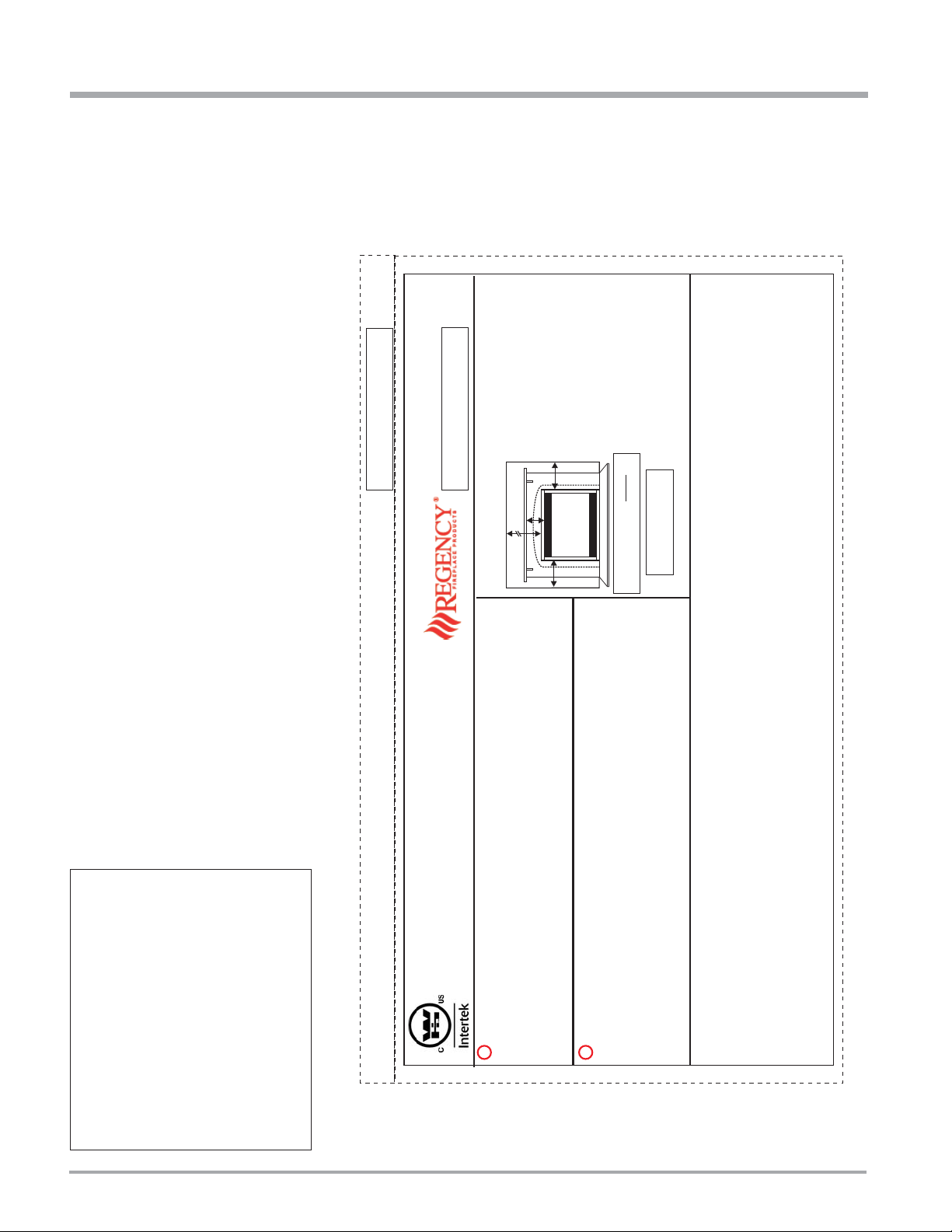
DO NOT REMOVE THIS LABEL / NE PAS ENLEVER CETTE ÉTIQUETTE
360
360
DOOR SEAL: Please
check that the door is
properly sealed
Minimum Clearances to Combustibles /
Degagement Minimum De Materiaux Combustibles
Serial No./ No de serie
918-853
The "Bay Louvers" be
used with the Bay Glass option
MUST
MAY BE INSTALLED IN MANUFACTURED (MOBILE) HOMES AFTER FIRST SALE.
Duplicate S/N
B
B
32"
Ceiling
Wall
Wall
A
0" Clearance to
combustibles from:
Mantel Clearances from Top:
Side Wall Clearance
from Side Facing
Alcove Clearances:
Minimum Vent Clearances:
Top, sides, bottom and rear of unit
(A) Min. 7" (177mm)
B) 6" with Flush or Bay Front
B) 8" with Barcelona Trim
Alcove approved for
Bay & Flush Louvers.
Max. Depth 36" (914mm)
Min. Width 48" (1219mm),
Min. Height 72" (1229mm)
Vertical Vent 1-1/4" (32mm)
Horizontal Top 2" (51mm)
Horizontal Side 1-1/2" (38mm)
Horizontal Bottom 1-1/2" (38mm)
(See Instruction Manual for detailed instructions)
ÉÉQUIP A L'UISINE POUR GAZ PROPANE
PROPANE GAS: Model P36E-LP4
11” WC/C.E. (2.73 kPa)
10" WC/C.E. (2.49 kPa)
6.4" WC/C.E. (1.59 kPa)
Minimum supply pressure
Manifold pressure High
Manifold pressure Low
Pression d'allimentation minimum
Pression la tubulure d' chappement lev e
Pression la tubulure d' chappement basse
àééé
àé
28,500 Btu for altitude 0 - 4500 ft.
Maximum Input
Minimum Input
Orifice size
Altitude
28,500 Btu/h (8.35 Kw/h)
22,000 Btu/h (6.44 Kw/h)
#52 DMS
0-4500 ft/pi (0-1372m)
D bit Calorifique maximum
D bit Calorifique minimum
Dimensions de l'orifice
L'altitude
é
é
Minimum supply pressure
Manifold pressure high
Manifold pressure low
Orifice size
Minimum input
Maximum input
Altitude
NATURAL GAS: Model P36E-NG4
APPAREIL FONCTIONNANT AU NATURAL GAS
CONCU POUR ETRE POELE: Mod le P36E-NG4
Pression d'allimentation minimum
Pression à la tubulure d' chappement lev e
Pression à la tubulure d' chappement basse
Grandeur de l'injecteur
D bit minimum selon
D bit maximum selon
l'altitude
Calorifique
Calorifique
é
ééé
é
é
é
5” (1.25 kPa)
3.5" (0..87 kPa)
1.6" (0.27 kPa)
#37 DMS
0-4500 ft/pi (0-1372m)
WC/C.E.
WC/C.E.
WC/C.E.
19,500 Btu/h (5.71 kW)
29,500 Btu/h (8.65 kW)
This appliance must be installed in accordance with local codes, if any; if none, follow the National Fuel Gas Code, ANSI Z223.1, or Natural Gas and Propane Installation Code, CSA B149.1.
This appliance must beinstalled in accordance with the Standard CAN/CSAZ240 MH, Mobile Housing, inCanada, or with the ManufacturedHome Construction and Safety Standard, Title 24 CFR, Part 3280, inthe United
States, orwhen sucha standard isnot applicable,ANSI/NCSBCS A225.1/NFPA 501A,Manufactured Home InstallationsStandard
This applianceis onlyfor use withthe typeof gas indicatedon therating plate andmay beinstalled in anaftermarket, permanentlylocated, manufactured (mobile)home wherenot prohibited bylocal codes.Seeowner's manual
for details. LP ConversionKit#514-972
Installer l'appareilselon lescodes ou règlementslocaux, ou,en l'absence detels règlements,selon les codesd'installation ANSIZ223.1, NationalFuel Gas Codeou CSA-B149.1en vigueur.
Installer l'appareil selon la norme CAN/CSA-Z240,Série MM, Maison mobiles ou CAN/CSA-Z240VC, Véhicules de camping, ou la norme24 CFR Part 3280, Manufactured HomeConstruction and Safety Standard. Si ces
normes nesont paspertinentes, utilisez lanorme ANSI/NCSBCSA225.1/NFPA501A, ManufacturedHome Installations Standard.
For usewith glassdoors certified withthe applianceonly
This ventedgas fireplaceheater is notfor usewith air filters. Nepas utiliserde filtre àair avecce foyer augaz àévacuation.
Fan (Part# 432-917) Optional Bay Window(Part #510-930)Option: HeatWaveKit # 946-556
Electrical supply/ Électrique115VAC,1.13A, 60Hz.
Cet appareildoit êtreutilize uniquement avec le typede gaz indiqué surla plaque signalétique. Cet appareilpeut être installé dansune maison préfabriquée ou mobile(É.-U. seulement) installée àdemeure si les règlements
locaux lepermettent. Voirla noticede l'utilisateur pourplus derenseignements. Cet appareilne peutpas être utiliséavec d'autresgaz sauf siune troussede conversion certifiéeest fournie.
Pour utilisationuniquement avecles portes enverre certifiéesavec l'appareil
Made in Canada/
Fabrique au Canada
FPI Fireplace Products International Ltd.Delta, BC, Canada
Listed:
Certified for/Certifi e pour:
Tested to:
WN# 16546
CANADA and U.S.A.
CAN/CGA-2.17-M91, ANSI Z21.88-2009 / CSA 2.33-2009
VENTED GAS FIREPLACE HEATER / FOYER AU GAZ À ÉVACUATION
é
VENTED GAS FIREPLACE HEATER - NOT FOR USE WITH SOLID FUELS.
NE PAS UTILISER AVEC DUCOMBUSTIBLE SOLIDE.FOYER AU GAZ À ÉVACUATION -
This is a copy of the label that accompanies
each P36E Zero Clearance Direct Vent
Gas Fireplace. We have printed a copy
of the contents here for your review. The
safety label is located on the front inside
base of the unit, visible when the bottom
louver is open.
NOTE: FPI units are constantly being
improved. Check the label on the unit and
if there is a difference, the label on the unit
is the correct one.
For the State of Massachusetts, installation
and repair must be done by a plumber or
gasfi tter licensed in the Commonwealth of
Massachusetts.
For the State of Massachusetts, fl exible
connectors shall not exceed 36 inches in
length.
For the State of Massachusetts, the appliances individual manual shut-off must be a
t-handle type valve.
The State of Massachusetts requires the
installation of a carbon monoxide alarm in
accordance with NFPA 720 and a CO alarm
with battery back up in the same room where
the gas appliance is installed.
6
P36E-4 Zero Clearance Direct Vent Gas Fireplace

REQUIREMENTS
MA Code - CO Detector
(for the State of Massachusetts only)
5.08: Modifications to NFPA-54, Chapter 10
(2) Revise 10.8.3 by adding the following additional requirements:
(a) For all side wall horizontally vented gas fueled equipment installed in every dwelling, building or structure used in whole or in part for
residential purposes, including those owned or operated by the Commonwealth and where the side wall exhaust vent termination is less than
seven (7) feet above finished grade in the area of the venting, including but not limited to decks and porches, the following requirements shall
be satisfied:
1. INSTALLATION OF CARBON MONOXIDE DETECTORS. At the time of installation of the side wall horizontal vented gas fueled
equipment, the installing plumber or gasfitter shall observe that a hard wired carbon monoxide detector with an alarm and battery back-up is
installed on the floor level where the gas equipment is to be installed. In addition, the installing plumber or gasfitter shall observe that a battery
operated or hard wired carbon monoxide detector with an alarm is installed on each additional level of the dwelling, building or structure
served by the side wall horizontal vented gas fueled equipment. It shall be the responsibility of the property owner to secure the services of
qualified licensed professionals for the installation of hard wired carbon monoxide detectors
a. In the event that the side wall horizontally vented gas fueled equipment is installed in a crawl space or an attic, the hard wired carbon
monoxide detector with alarm and battery back-up may be installed on the next adjacent floor level.
b. In the event that the requirements of this subdivision can not be met at the time of completion of installation, the owner shall have a period of
thirty (30) days to comply with the above requirements; provided, however, that during said thirty (30) day period, a battery operated carbon
monoxide detector with an alarm shall be installed.
2. APPROVED CARBON MONOXIDE DETECTORS. Each carbon monoxide detector as required in accordance with the above provisions
shall comply with NFPA 720 and be ANSI/UL 2034 listed and IAS certified.
3. SIGNAGE. A metal or plastic identification plate shall be permanently mounted to the exterior of the building at a minimum height of eight
(8) feet above grade directly in line with the exhaust vent terminal for the horizontally vented gas fueled heating appliance or equipment. The
sign shall read, in print size no less than one-half (1/2) inch in size, "GAS VENT DIRECTLY BELOW. KEEP CLEAR OF ALL
OBSTRUCTIONS".
4. INSPECTION. The state or local gas inspector of the side wall horizontally vented gas fueled equipment shall not approve the installation
unless, upon inspection, the inspector observes carbon monoxide detectors and signage installed in accordance with the provisions of 248 CMR
5.08(2)(a)1 through 4.
(b) EXEMPTIONS: The following equipment is exempt from 248 CMR 5.08(2)(a)1 through 4:
1. The equipment listed in Chapter 10 entitled "Equipment Not Required To Be Vented" in the most current edition of NFPA 54 as adopted by
the Board; and
2. Product Approved side wall horizontally vented gas fueled equipment installed in a room or structure separate from the dwelling, building or
structure used in whole or in part for residential purposes.
(c) MANUFACTURER REQUIREMENTS - GAS EQUIPMENT VENTING SYSTEM PROVIDED. When the manufacturer of Product
Approved side wall horizontally vented gas equipment provides a venting system design or venting system components with the equipment, the
instructions provided by the manufacturer for installation of the equipment and the venting system shall include:
1. Detailed instructions for the installation of the venting system design or the venting system components; and
2. A complete parts list for the venting system design or venting system.
(d) MANUFACTURER REQUIREMENTS - GAS EQUIPMENT VENTING SYSTEM NOT PROVIDED. When the manufacturer of a
Product Approved side wall horizontally vented gas fueled equipment does not provide the parts for venting the flue gases, but identifies
"special venting systems", the following requirements shall be satisfied by the manufacturer:
1. The referenced "special venting system" instructions shall be included with the appliance or equipment installation instructions; and
2. The "special venting systems" shall be Product Approved by the Board, and the instructions for that system shall include a parts list and
detailed installation instructions.
(e) A copy of all installation instructions for all Product Approved side wall horizontally vented gas fueled equipment, all venting instructions,
all parts lists for venting instructions, and/or all venting design instructions shall remain with the appliance or equipment at the completion of
the installation.
P36E-4 Zero Clearance Direct Vent Gas Fireplace 7
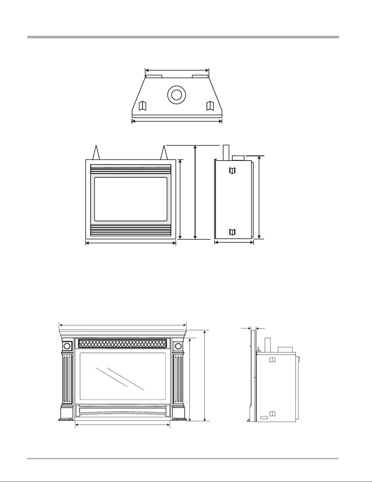
DIMENSIONS
UNIT DIMENSIONS
33-1/4” (838mm)
36” (914mm)
36” (940mm)
30-1/2” (775mm)
36” (914mm)
12-3/4” (324mm)
HAMPTON FACEPLATE DIMENSIONS
43-1/4” (1099mm)
32-1/2” (826mm)
1-1/4” (32mm)
31-1/4” (794mm)
29-1/2” (749mm)
32-1/4” (819mm)
8
P36E-4 Zero Clearance Direct Vent Gas Fireplace
INSTALLATION
IMPORTANT MESSAGE
SAVE THESE
INSTRUCTIONS
The P36E-NG or P36E-LP Direct Vent Fireplace
must be installed in accordance with these
instructions. Carefully read all the instructions
in this manual fi rst. Consult the "authority
having jurisdiction" to determine the need for
a permit prior to starting the installation. It is
the responsibility of the installer to ensure
this fi replace is installed in compliance with
manufacturer's instructions and all applicable
codes.
BEFORE YOU ST ART
Safe installation and operation of this appliance
requires common sense, however, we are
required by the Canadian Safety Standards
and ANSI Standards to make you aware of
the following:
INSTALLATION AND REPAIR SHOULD
BE DONE BY A QUALIFIED SERVICE
PERSON. THE APPLIANCE SHOULD
BE INSPECTED BEFORE USE
AND AT LEAST ANNUALLY BY A
PROFESSIONAL SERVICE PERSON.
MORE FREQUENT CLEANING MAY
BE REQUIRED DUE TO EXCESSIVE
LINT FROM CARPETING, BEDDING
MATERIAL, ETC. IT IS IMPERATIVE
THAT CONTROL COMPARTMENTS,
BURNERS AND CIRCULATING AIR
P ASSAGEWA YS OF THE APPLIANCE
BE KEPT CLEAN.
DUE TO HIGH TEMPERA TURES, THE
APPLIANCE SHOULD BE LOCATED
OUT OF TRAFFIC AND AWAY FROM
FURNITURE AND DRAPERIES.
WARNING: F AILURE TO INSTALL THIS
APPLIANCE CORRECTL Y WILL VOID
YOUR WARRANTY AND MAY CAUSE
A SERIOUS HOUSE FIRE.
CHILDREN AND ADULTS SHOULD
BE ALERTED TO THE HAZARDS OF
HIGH SURFACE TEMPERATURES,
ESPECIALLY THE FIREPLACE
GLASS, AND SHOULD STAY AWAY
TO AVOID BURNS OR CLOTHING
IGNITION.
GENERAL SAFETY
INFORMATION
1) The appliance installation must conform
with local codes or, in the absence of local
codes, with the current Canadian or National
Gas Codes, CAN1-B149 or ANSI Z223.1
Installation Codes.
2) The appliance when installed, must be
electrically grounded in accordance with
local codes, or in the absence of local codes
with the current National Electrical Code,
ANSI/NFPA 70 or CSA C22.1 Canadian
Electrical Code.
3) See general construction and assembly
instructions. The appliance and vent should
be enclosed.
4) This appliance must be connected to the
specifi ed vent and termination cap to the
outside of the building envelope. Never vent
to another room or inside a building. Make
sure that the vent is fi tted as per Venting
instructions.
5) Inspect the venting system annually for
blockage and any signs of deterioration.
6) Venting terminals shall not be recessed into
a wall or siding.
7) Any safety glass removed for servicing
must be replaced prior to operating the
appliance.
8) To prevent injury, do not allow anyone who
is unfamiliar with the operation to use the
fi replace.
9) Wear gloves and safety glasses for protection while doing required maintenance.
10) Be aware of electrical wiring locations in
walls and ceilings when cutting holes for
termination.
11) Under no circumstances should this
appliance be modifi ed. Parts that have to be
removed for servicing should be replaced
prior to operating this appliance.
12) Installation and any repairs to this appliance
should be done by a qualifi ed service per-
son. A professional service person should
be called to inspect this appliance annually.
Make it a practice to have all of your gas
appliances checked annually.
13) Do not slam shut or strike the glass door.
14) Under no circumstances should any solid fuels
(wood, paper, cardboard, coal, etc.) be used
in this appliance.
15) The appliance area must be kept clear and
free of combustible materials, (gases and
other fl ammable vapours and liquids).
Emissions from burning wood or gas could
contain chemicals known to the State of
California to cause cancer, birth defects or
other reproductive harm.
INSTALLATION
CHECKLIST
1) Locate appliance. Refer to the following
sections:
a) Locating Your Gas Fireplace
b) Clearances
c) Combustible Mantel Clearances
d) Framing & Finishing
e) Venting
2) Assemble Top Standoffs and Top Facing
Support and Side Nailing Strips (Refer to the
"Unit Assembly Prior to Installation" section).
NOTE: Must be done before installing unit
into fi replace.
3) Install vent (Refer to the "Venting"
sections).
4) Make gas and electrical connections. Test
the pilot. Must be as per diagram (Refer to
the "Pilot Adjustment " section).
Convert to propane if desired (Refer to the
"Conversion from NG to LP" section).
YOUNG CHILDREN SHOULD BE
CAREFULLY SUPERVISED WHEN
THEY ARE IN THE SAME ROOM AS
THE APPLIANCE.
CLOTHING OR OTHER FLAMMABLE
MA TERIAL SHOULD NOT BE PLACED
ON OR NEAR THE APPLIANCE.
P36E-4 Zero Clearance Direct Vent Gas Fireplace 9
INSTALLATION
5) Install standard and optional features. Refer
to the following sections where applicable:
a. Install 4 AA batteries into battery pack
b. Optional Brick Panels
c. Log Set Installation
d. Standard Flush Door
e. Regency Flush or Bay Fronts
f. Hampton Cast Faceplate
g. Remote Control
h. Wall Switch
i. Wall Thermostat
j. Fan Installation
6) Final check.
Before leaving this unit with the customer,
the installer must ensure that the appliance is
fi ring correctly and operation fully explained
to customer.
This includes:
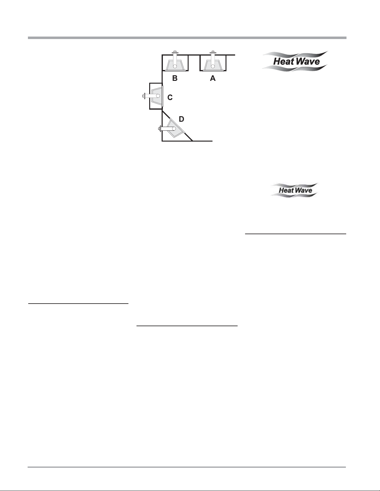
Diagram 1
A) Flat on Wall
B) Flat on Wall Corner
C) Recessed into Wall/Alcove
D) Corner
HEATWAVE
DUCT SYSTEM
OPTIONAL KIT #946-556
The HeatWave Air Duct Kit increases the
effectiveness of your fi replace by dispersing
warm air from the fi replace to remote locations in
the same room or other rooms in your home.
Up to two kits may be installed on the
fi replace.
Please Note: Only 1 HeatWave kit may be
operated at one time. This includes the internal
blower option as well.
1) Clocking the appliance to ensure the correct
fi ring rate (rate noted on label 29,500 NG
/ 28,500 LP Btu/h) after burning appliance
for 15 minutes.
2) If required, adjusting the primary air to
ensure that the fl ame does not carbon.
First allow the unit to burn for 15-20 min.
to stabilize.
CAUTION:
Any alteration to the product that causes
sooting or carboning that results in
damage is not the responsibility of the
manufacturer.
LOCATING YOUR
GAS FIREPLACE
1) When selecting a location for your fi replace,
ensure that the clearances outlined on this
page are met.
2) Provide adequate clearances for
servicing.
3) The appliance must be installed on a fl at,
solid, continuous surface (e.g. wood, metal,
concrete). This may be the fl oor, or raised up
on a platform to enhance its visual impact.
If the appliance is going to be installed
on carpeting, combustible linoleum tile or
other combustible material other than wood
fl ooring, the appliance must be installed on
a metal or wood panel extending the full
width and depth of the appliance.
5) This appliance is Listed for bedroom
installations when used with a Listed Millivolt
Thermostat. Some areas may have further
requirements, check local codes before
installation.
6) The P36E Direct Vent Gas Fireplace is
approved for alcove installations, which
meet the clearances listed on this page.
7) We recommend that you plan your installation
on paper using exact measurements for
clearances and fl oor protection before
actually installing this appliance. Have a
qualifi ed inspector, dealer , or installer review
your plans before installation.
Note: For vent terminations see the
"Exterior Vent Termination
Locations" section.
MANUFACTURED
MOBILE HOME
ADDITIONAL
REQUIREMENTS
1) Ensure that structural members are not cut
or weakened during installation.
2) Ensure proper grounding using the #8
ground lug provided. See the "Alternate
Wiring Diagram for Wall Switch" section.
The HeatWave Duct Kit has different
clearance and framing requirements, check
the HeatWave manual for details.
OPTIONAL
HEAT RELEASE KIT
#946-570
The Heat Release Kit expels warm air from
the fi replace to the outside of the building,
allowing the fi replace to be operated with less
heat entering the room. The kit may be used on
either the left or right side.
4) The P36E Direct Vent Gas Fireplace can be
installed in a recessed position or framed
out into the room as in A, B, C, D. See
Diagram 1.
10
P36E-4 Zero Clearance Direct Vent Gas Fireplace
INSTALLATION
CLEARANCES
The clearances listed below are Minimum distances unless otherwise stated:
A major cause of chimney related fi res is failure to maintain required clearances (air space) to combustible materials. It is of the greatest
importance that this fi replace and vent system be installed only in accordance with these instructions.
IMPORTANT: See the "Regency Tripoli Screen Door Series Framing Note" section for framing note on Tripoli Screen Door.
Clearance to Combustibles from:
Back 0" (0mm)
Side 0" (0mm)
Floor 0" (0mm)
NOTE: The minimum fl oor clearance must be maintained from the top surface of the carpeting, tile, etc.
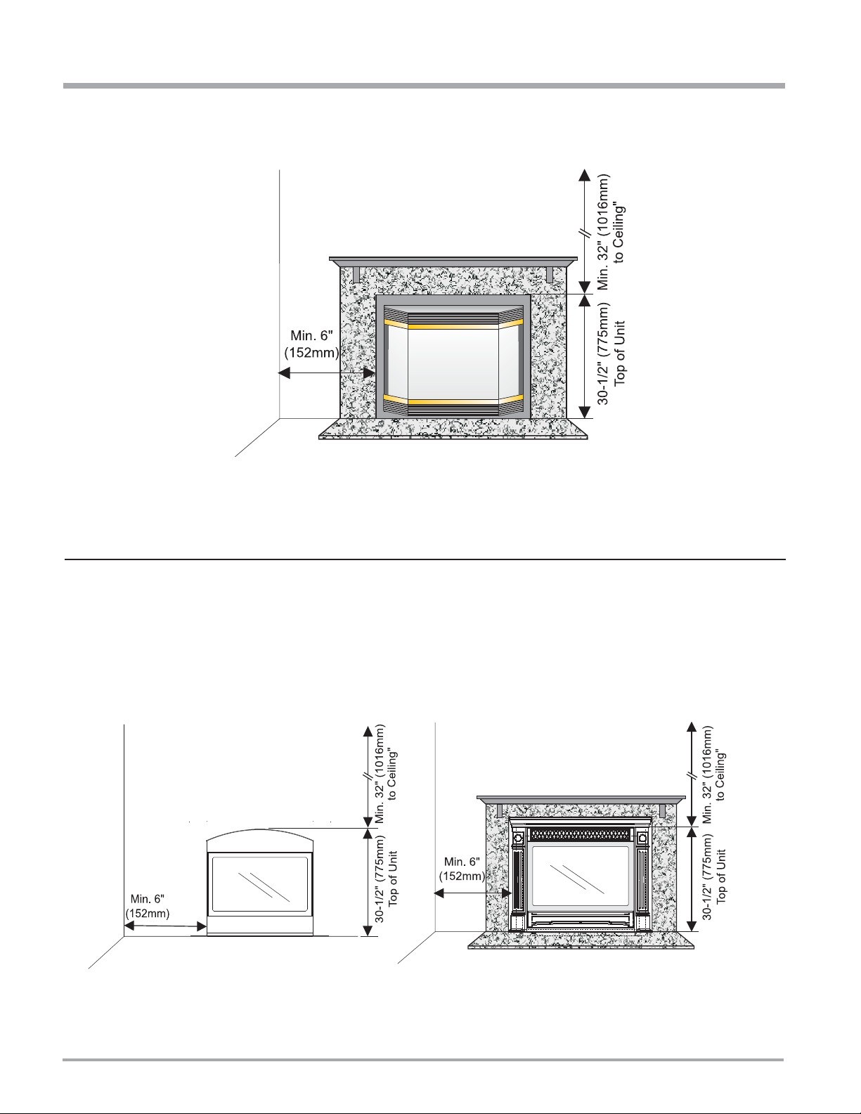
Minimum Clearance from Top of Unit to:
Ceiling from top of unit. 32" (1016mm)
Side Wall Clearances:
Bay or Flush Front 6"* (152mm)
Cast Faceplate 6"* (152mm)
Kensington Front 6"* (152mm)
Balmoral 6"* (152mm)
Full Screen Doors 6"* (152mm)
* Measured from Surround or Front. See the "Regency Clearances for dimensions" section.
Horizontal Vent Clearances:
Top 2" (51mm)
Side 1-1/2" (38mm)
Bottom 1-1/2" (38mm)
Vertical Vent Clearances 1-1/4" (32mm)
Alcove Clearances**:
Max. Depth 36" (914mm)
Min. Width 48" (1219mm)
Min. Height 72" (1829mm)
WARNING: Fire hazard is an extreme risk if these clearances are not adhered to.
Barcelona & Double Screen Door Installations
Heat Release Kit
The HeatWave Duct Kit and the Heat
Release Kit have different clearance
and framing requirements, check the
HeatWave and Heat Release manual
for details.
T o install the combination of the Barcelona front and screen doors you
must use non-combustible mantel in conjunction with the already
required framing specs for the Barcelona front. Steel studs and
non-combustible material on the facing must be adhered to.
P36E-4 Zero Clearance Direct Vent Gas Fireplace 11
INSTALLATION
REGENCY® CLEARANCES
Clearances for Bay Front, Flush Front
TRIPOLI SCREEN
DOOR CLEARANCES
& Full Screen Doors
HAMPTON® CLEARANCES
12
P36E-4 Zero Clearance Direct Vent Gas Fireplace
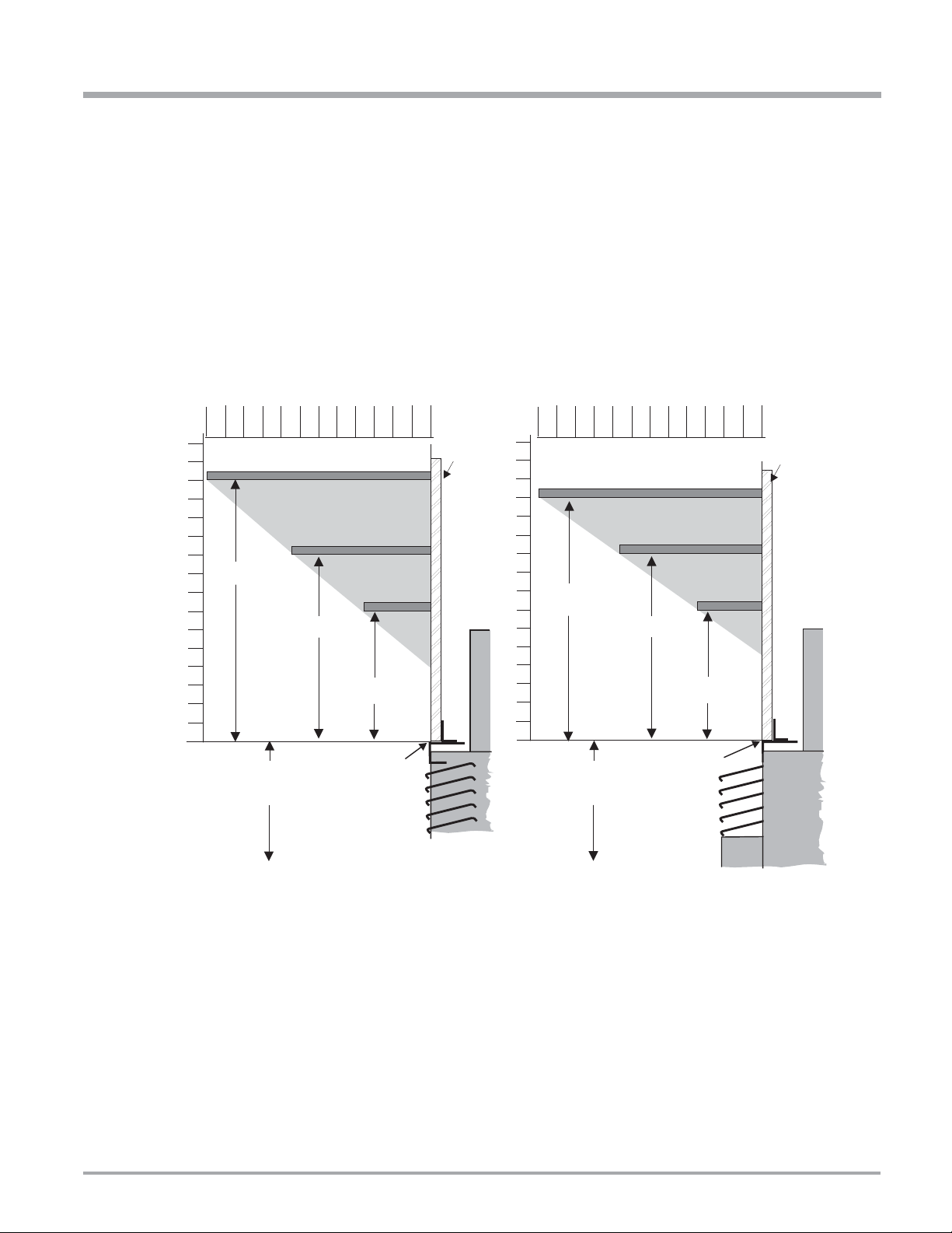
Drywall
12" Mantel
7 1/2" Mantel
3 1/2"
Mantel
Mantel Clearances with
Flush Glass / Full Screen Doors
14"
7"
10"
30-1/2"
to floor
2
0
12
6
4
810
2
0
12
6
16
4
14
8
10
Side View
Top of
Unit
30-1/2"
to floor
2
0
12
6
4
810
12" Mantel
7 3/4“ Mantel
3 1/2"
Mantel
Mantel Clearances
with Bay Option
13"
2
0
12
6
16
4
14
8
10
Drywall
Top of
Unit
7"
10"
Side View
6" Standoff
6" Standoff
INSTALLATION
REGENCY® SERIES COMBUSTIBLE MANTEL CLEARANCES
Note: A non-combustible mantel may be installed at a lower height if the framing is made of metal studs covered with a non-combustible
board.
Because of the extreme heat this fi replace emits, the mantel clearances are critical.
Combustible mantel clearances from top of unit are shown in Diagrams 1 & 2.
These drawings are to scale at 1:6 (one inch = 6 inches)
Mantel can be installed anywhere in shaded area or higher using the above scale.
Note: Ensure the paint that is used on the mantel and the facing is "heat resistant" or the paint may discolour.
Diagram 1
Diagram 2
P36E-4 Zero Clearance Direct Vent Gas Fireplace 13
INSTALLATION
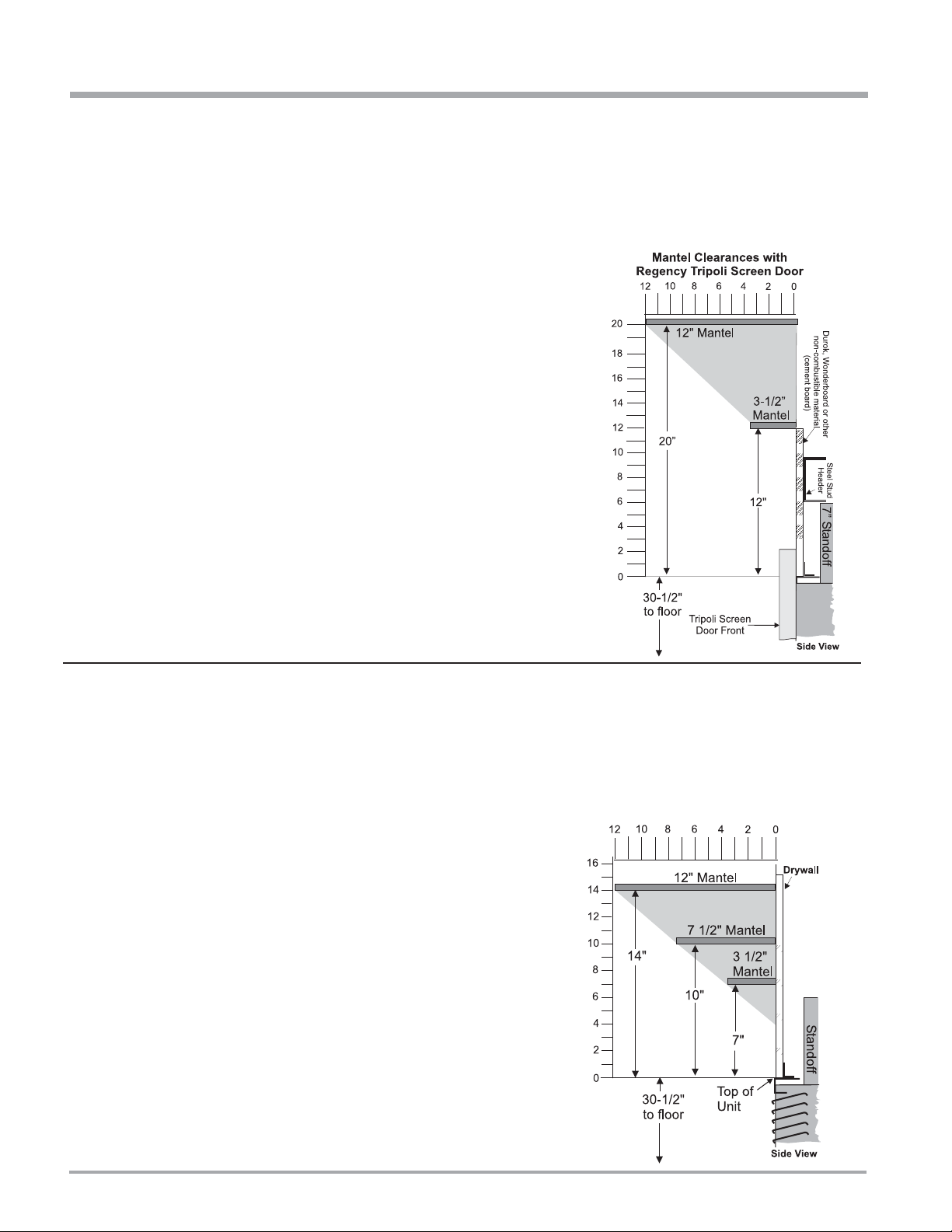
TRIPOLI SCREEN DOOR COMBUSTIBLE MANTEL CLEARANCES
Because of the extreme heat this fi replace emits, the mantel clearances are critical.
Combustible mantel clearances from top of unit are shown in the diagram below.
Note: A non-combustible mantel may be installed at a lower height if the framing is made of metal studs covered with a non-combustible
board.
These drawings are to scale at 1:6 (one inch = 6 inches)
Mantel can be installed anywhere in shaded area or higher using
the above scale.
Note: Ensure the paint that is used on the mantel and the
facing is "heat resistant" or the paint may discolour.
HAMPTON® COMBUSTIBLE MANTEL CLEARANCES
Because of the extreme heat this fi replace emits, the mantel clearances are critical.
Combustible mantel clearances from top of unit are shown in the diagram below.
Note: A non-combustible mantel may be installed at a lower height if the framing is made of metal studs covered with a non-combustible
board.
These drawings are to scale at 1:6 (one inch = 6 inches)
Mantel can be installed anywhere in shaded area or higher using
the above scale.
Note: Ensure the paint that is used on the mantel and the
facing is "heat resistant" or the paint may discolour.
Mantel Clearances with
Hampton Cast Faceplate
®
7"
14
P36E-4 Zero Clearance Direct Vent Gas Fireplace
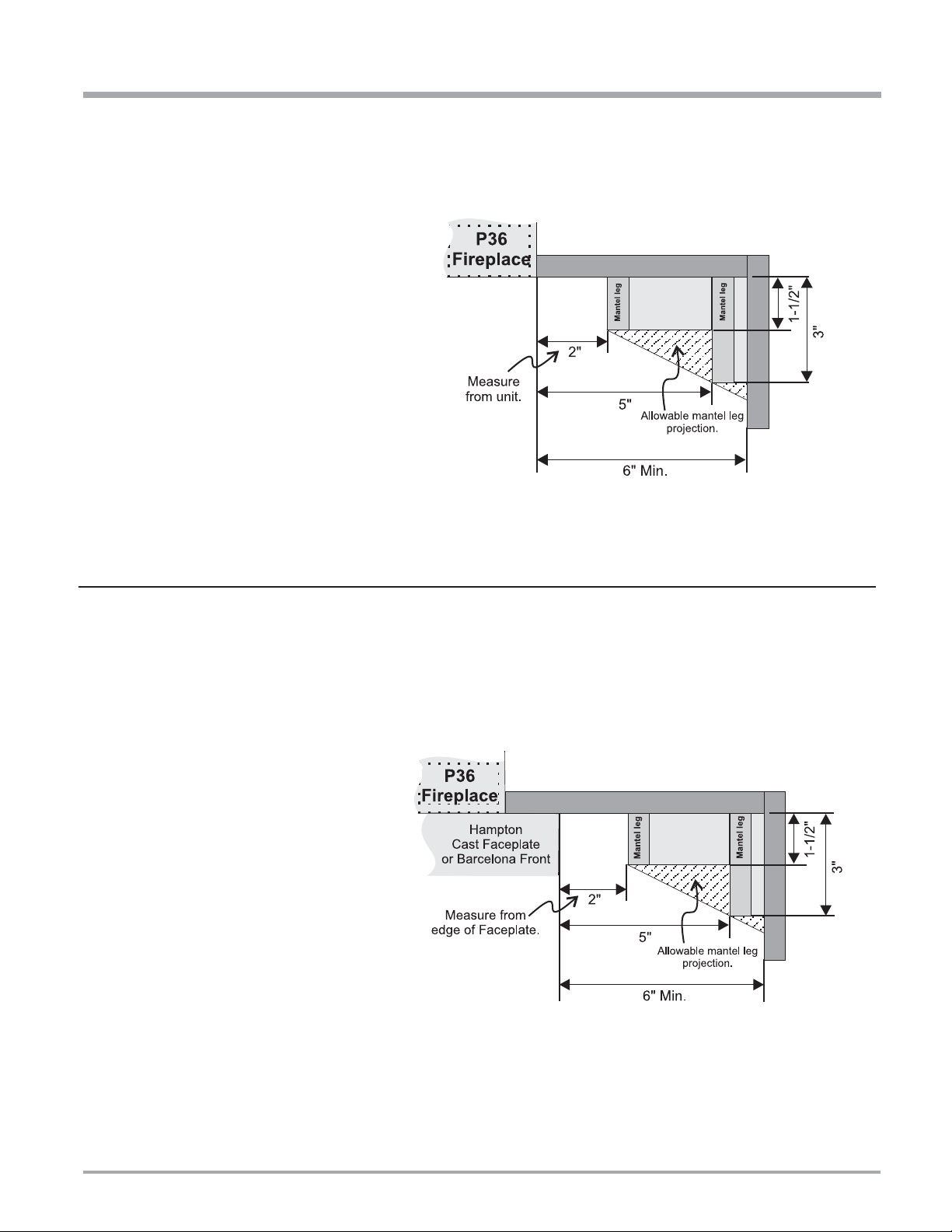
MANTEL LEG CLEARANCES
Combustible mantel leg clearances as per diagram:
INSTALLATION
REGENCY®
Maximum 1-1/2" projection
at 2" minimum clearance.
HAMPTON® MANTEL LEG CLEARANCES
Combustible mantel leg clearances as per diagram:
Hampton Cast Faceplate Width: 43-1/4"
Maximum 1-1/2" projection
at 2" minimum clearance.
P36E-4 Zero Clearance Direct Vent Gas Fireplace 15
INSTALLATION
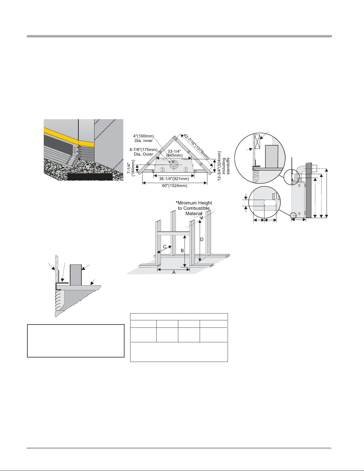
FRAMING AND FINISHING
IMPORTANT FINISHING DETAIL NOTE:
When installing tile, carpeting, or any other
fi nishing material in front of the unit, the
top of the surface of the tile, carpeting, etc.
must not be any higher than the base of
the fi replace. Any higher and the optional
accessories will not fi t (i.e. fi nishing trim,
surrounds, etc.)
Floor Finishing Material
NOTE: Floor Finishing Material
must not be any higher than the
base of the fi replace.
1) Determine the total thickness of facing
material (e.g. drywall plus ceramic tiles) to
allow the fi nished surface to be fl ush with
the front of the unit. Total facing thickness
can vary from 1/2" (13mm) to 1-1/4" (32mm)
thick.
2) Frame in the enclosure for the unit with
framing material. The framed opening is
36-1/4" high x 36-1/4" wide x 12-3/4" deep
(921mm high x 921mm wide x 324mm
deep).
Note: Header must be installed vertically. If
Header is installed horizontally, it must be
steel.
3) For exterior walls, insulate the enclosure to
the same degree as the rest of the house,
apply vapour barrier and drywall, as per
local installation codes. (Do not insulate
the fi replace itself.)
4) The top of the unit must not be closer than
32" (813mm) to the ceiling.
Top Header
10" dia. hole
1/2"
Drywall
2"
3-1/2"
Opening for gas
connection
4"
through wall
for Flex
or for DuraVent
12-3/4"
36"
32-1/2"
40-1/2"
Top Facing
Drywall
Support
(or other
facing)
Install Side Nailing Strips, Top Facing
Support, and Top Standoffs before unit
is slipped into position. See the "Unit
Assembly Prior to Installation" section for
assembly details.
6” (152mm)
Standoff
Top of unit
NOTE: See next page for important
Barcelona Series framing note.
Framing Dimensions
A B C D
36-1/4" 36-1/4" 12-3/4" 46"*
921mm 921mm 324mm 1168mm*
* 'D' is Minimum height to combustible materials including the Minimum 2" (51mm) Top
clearance to the Horizontal Vent.
Note: 40-1/2" (1029mm) is the minimum
height for both fl ex termination or
rigid pipe venting.
Note: The unit does not have to be
completely enclosed in a chase. The
clearance on top of the unit is 0" to
the standoffs so combustible building
materials can be laid directly on top
of the standoffs. You must maintain
1-1/2" (38mm) clearance from the
vent to combustible materials for fl ex
(1-1/4" for Rigid Pipe).
5) Use steel studs for framing where the 1-
1/2" (38mm) clearance from the vent to
combustible material cannot be maintained,
e.g. front top header.
16
P36E-4 Zero Clearance Direct Vent Gas Fireplace
INSTALLATION
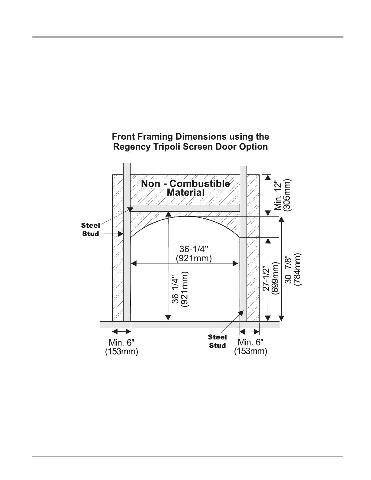
REGENCY® TRIPOLI SCREEN DOOR SERIES FRAMING NOTE
When installing the optional Tripoli Screen Door Series, a non-combustible material 12" (305mm) above the unit and 6" (153mm) on each side
must be used (see Diagram 2). For complete framing details see page 57.
The Tripoli Screen Door Series also requires steel stud framing above and on each side of the unit (refer to Diagram 1).
Diagram 1
P36E-4 Zero Clearance Direct Vent Gas Fireplace 17
INSTALLATION
Side
Nailing Strips
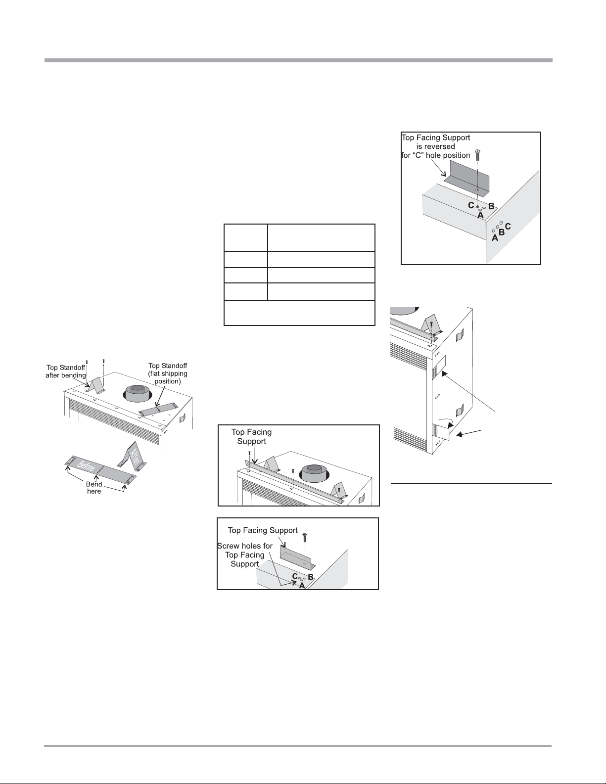
UNIT ASSEMBLY
PRIOR TO
INSTALLATION
The T op Facing Support, the Side Nailing Strips
and the 2 Top Standoffs must be correctly
positioned and attached to the top before unit
is slipped into position.
Top Standoff Assembly
The top standoffs are shipped in a fl at position
and must be folded into shape and attached.
1) Remove the standoffs from the fi replace top.
2) T ake each standoff and bend into the correct
shape. Bend up at the bend lines until the
screw holes in the standoff and the prepunched screw holes on the fi replace top
line up.
3) Attach the standoff securely to the top with
2 screws per standoff (on opposite corners).
Top Facing Support &
Side Nailing Strips
Determine the total thickness of facing material
(e.g. drywall plus ceramic tiles) to allow the
fi nished surface to be fl ush with the front of the
unit. Total facing thickness can vary from 1/2"
(13mm) to 1-1/4" (32mm) thick.
The Top Facing Support can be mounted in 3
different positions depending on the thickness
of the facing material.
Screw
Position
A 1/2" / 13mm
B 7/8" / 22mm
C* 1-1/4" / 32mm
* For "C" screw position the top facing
support is reversed.
1) Mount Top Facing Support using the 3
supplied screws into the three pre-punched
screw holes on the top front of the unit. Use
hole positions A, B, or C depending on your
facing depth.
Facing Material
Depth
"C" Screw Position:
For a facing material depth of 1-1/4" (32mm),
the top facing support must be reversed.
2) Fold out the two nailing strips on each side.
18
VENTING
INTRODUCTION
The P36E uses the "balanced fl ue" technology
Co-Axial system. The inner liner vents products
of combustion to the outside while the outer
liner draws outside combustion air into the
combustion chamber thereby eliminating the
need to use heated room air for combustion and
losing warm room air up the chimney.
Note: These flue pipes must not be
connected to any other appliance.
The gas appliance and vent system must be
vented directly to the outside of the building,
and never be attached to a chimney serving a
separate solid fuel or gas burning appliance.
Each direct vent gas appliance must use it's own
separate vent system. Common vent systems
are prohibited.
P36E-4 Zero Clearance Direct Vent Gas Fireplace
INSTALLATION
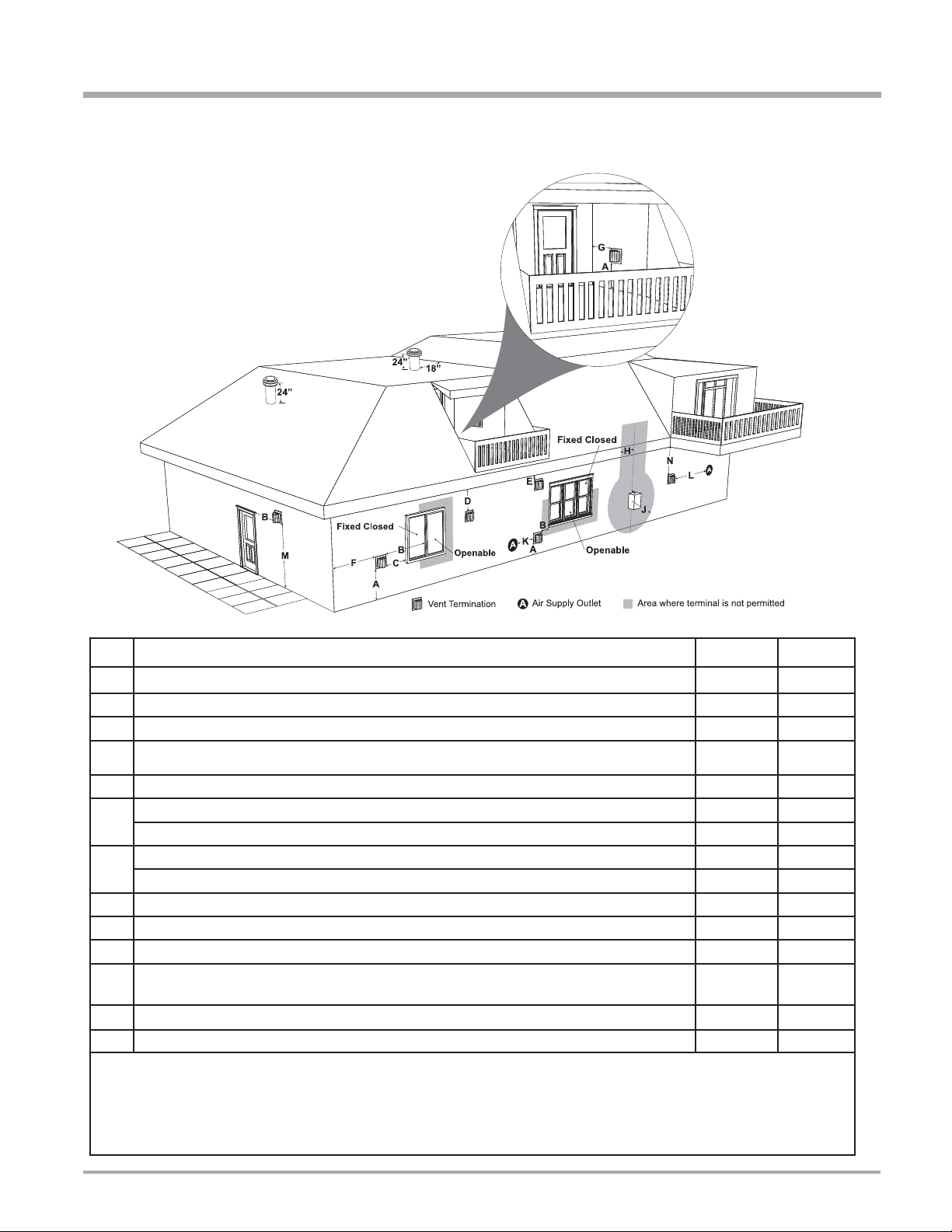
EXTERIOR VENT TERMINATION LOCATIONS
1
Minimum Clearance Requirements
A Clearance above grade, veranda, porch, deck, or balcony 12"(30cm) 12"(30cm)
B Clearance to window or door that may be opened 12"(30cm) 9" (23cm)
C Clearance to permanently closed window **
D Vertical clearance to ventilated soffi t located above the terminal within a horizontal distance of 2 feet (61cm)
from the center line of the terminal (check with the local code)
E Clearance to unventilated soffi t 15"(38cm) 15"(38cm)
F
Clearance to outside corner: with AstroCap Termination Cap.
Clearance to outside corner: with all other approved Termination Caps. 14"(36cm) 14"(36cm)
G
Clearance to inside corner: with AstroCap Termination Cap
Clearance to inside corner: with all other approved Termination Caps. 12"(30cm) 12"(30cm)
H Clearance to each side of center line extended above meter/regulator assembly 36"(90cm)
J Clearance to service regulator vent outlet 36"(90cm) *
K Clearance to non-mechanical air supply inlet to building or the combustion air inlet to any other appliance 12"(30cm) 9" (23cm)
L Clearance to a mechanical air supply inlet
#3' (91cm) above if within 10' (3m) horizontally.
M Clearance above paved sidewalk or a paved driveway located on public property 84"(2.1m)
N Clearance under veranda, porch, deck, or balcony 12"(30cm)
1
In accordance with current CSA B149.1, Natural Gas and Propane Installation Code
2
In accordance with the current ANSI Z223.1/NFPA 54, National Fuel Gas Code
┼
A vent shall not terminate directly above a sidewalk or paved driveway which is located between two single family dwellings and serves both dwellings.
‡ Permitted only if veranda, porch, deck, or balcony is fully open on a minimum of two sides beneath the fl oor.
Clearance in accordance with local installation codes and the requirements of the gas supplier
*
a
3 feet (91cm) within a height of 15 feet (4.5m) above the meter / regulator assembly
b
3 feet (91cm) above - if within 10 feet (3m) horizontally
Canada
18"(46cm) 18"(46cm)
6"(15cm) 6"(15cm)
6"(15cm) 6"(15cm)
a
72"(1.8m) 36"(90cm)
┼
‡
USA
2
*
b
*
*
P36E-4 Zero Clearance Direct Vent Gas Fireplace 19
INSTALLATION
VENTING
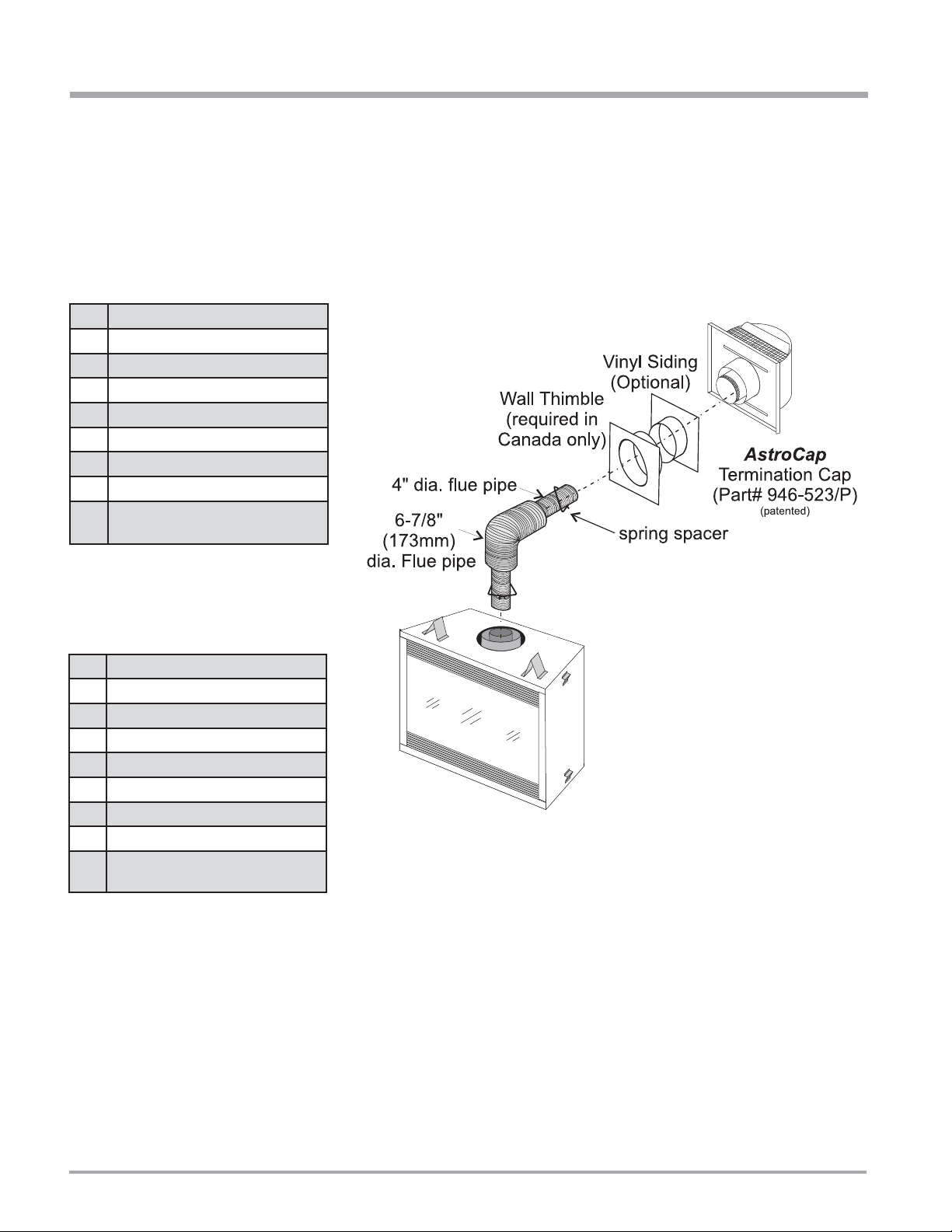
DIRECT VENT SYSTEM (FLEX)
HORIZONTAL TERMINATIONS ONLY
These venting systems, in combination with the P36E Direct Vent Gas Fireplace, have been tested and listed as a direct vent heater system by
Warnock Hersey . The location of the termination cap must conform to the requirements in the V ent Terminal Locations diagram in the "Exterior Vent
Termination Locations" section.
FPI Direct Vent (Flex) System T ermination Kit (Part # 946-515) includes all the parts needed to install the P36E with a maximum run of 4 feet.
1) 6-7/8" dia. fl exible liner (4 ft. length)
2) 4" dia. fl exible liner (4 ft. length)
3) spring spacers (4)
4) thimble (2)
5) AstroCap termination cap (1)
6) screws (12)
7) tube of Mill Pac (1)
8) plated screws (8)
9) screws #8 x 1-1/2" Drill Point, Stainless
Steel (4)
If longer runs are needed, the FPI Direct
Vent system (Flex) # 946-516 includes all
the parts needed to install the P36E with a
maximum 10' run.
1) 6-7/8" dia. fl exible liner (10 ft. length)
2) 4" dia. fl exible liner (10 ft. length)
3) spring spacers (7)
4) thimble (2)
5) AstroCap termination cap (1)
6) screws (12)
7) tube of Mill Pac (1)
8) plated screws (8)
9) screws #8 x 1-1/2" Drill Point, Stainless
Steel (4)
Notes:
1) Liner sections should be continuous without any joints or seams.
2) Only Flex pipe purchased from FPI may be used for Flex installations.
20
P36E-4 Zero Clearance Direct Vent Gas Fireplace
INSTALLATION
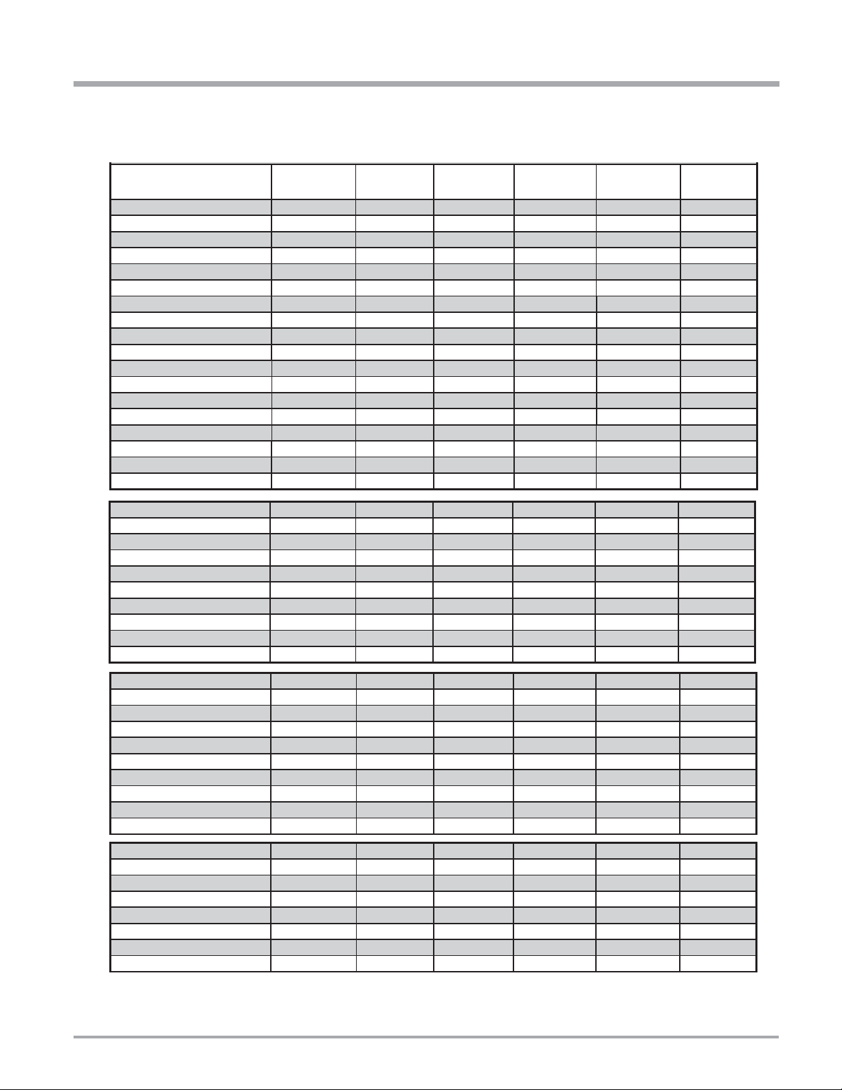
4” X 6-5/8” RIGID PIPE CROSS REFERENCE CHART
Components from different Manufacturers may not be mixed. Not All Rigid Pipe components are available directly from FPI.
Description
6” Pipe Length-Galvanized 46DVA-06 4DT-6 N/A 4D6 SV4L6 TC-4DL6
6” Pipe Length-Black 46DVA-06B 4DT-6B N/A 4D6B SV4LB6 TC-4DL6B
7” Pipe Length-Galvanized N/A N/A 4D7 N/A N/A N/A
7” Pipe Length-Black N/A N/A 4D7B N/A N/A N/A
9” Pipe Length-Galvanized 46DVA-09 4DT-9 N/A N/A N/A N/A
9” Pipe Length-Black 46DVA-09B 4DT-9B N/A N/A N/A N/A
12” Pipe Length-Galvanized 46DVA-12 4DT-12 4D12 4D12 SV4L12 TC-4DL1
12” Pipe Length-Black 46DVA-12B 4DT-12B 4D12B 4D12B SV4LB12 TC-4DL1B
18” Pipe Length-Galvanized 46DVA-18 4DT-18 4D18 4D18 SV4LA TC-4DL18
18” Pipe Length-Black 46DVA-18B 4DT-18B 4D18B 4D18B SV4LA TC-4DL18B
24” Pipe Length-Galvanized 46DVA-24 4DT-24 4D24 4D24 SV4L24 TC-4DL2
24” Pipe Length-Black 46DVA-24B 4DT-24B 4D24B 4D24B SV4LB24 TC-4DL2B
36” Pipe Length-Galvanized 46DVA-36 4DT-36 4D36 4D36 SV4L36 TC-4DL3
36” Pipe Length-Black 46DVA-36B 4DT-36B 4D36B 4D36B SV4LB36 TC-4DL3B
48” Pipe Length-Galvanized 46DVA-48 4DT-48 4D48 4D48 SV4L48 TC-4DL4
48” Pipe Length-Black 46DVA-48B 4DT-48B 4D48B 4D48B SV4LB48 TC-4DL4B
60” Pipe Length-Galvanized 46DVA-60 4DT-60 N/A N/A N/A N/A
60” Pipe Length-Black 46DVA-60B 4DT-60B N/A N/A N/A N/A
Adjustable Length 3”-10”-Galvanized N/A N/A N/A 4DAL N/A TC-4DLT
Adjustable Length 3”-10”-Black N/A N/A N/A 4DALB N/A TC-4DLTB
Adjustable Length 7”-Galvanized N/A N/A 4D7A N/A N/A N/A
Adjustable Length 7”-Black N/A N/A 4D7AB N/A N/A N/A
Extension Pipe 8-1/2”-Galvanized 46DVA-08A N/A N/A N/A N/A N/A
Extension Pipe 8-1/2”-Black 46DVA-08AB N/A N/A N/A N/A N/A
Adjustable Length 12”-Galvanized N/A N/A 4D12A N/A SV4LA12 N/A
Adjustable Length 12”-Black N/A N/A 4D12A N/A SV4LBA12 N/A
Extension Pipe 16”-Galvanized 46DVA-16A N/A N/A N/A N/A N/A
Extension Pipe 16”-Black 46DVA-16AB N/A N/A N/A N/A N/A
Simpson
Direct Vent Pro
®
Selkirk
Direct Temp™
American Metal
Products®
Amerivent Direct
Metal-Fab™
Sure Seal
Security
Secure- Vent®
ICC Excel
Direct
45º Elbow-Galvanized 46DVA-E45 4DT-EL45 4D45L N/A N/A TE-4DE45
45º Elbow-Black 46DVA-E45B 4DT-EL45B 4DT-EL45B N/A N/A TE-4DE45B
45º Elbow Swivel-Galvanized See 46DVA-E45 N/A N/A 4D45L SV4E45 N/A
45º Elbow Swivel-Black See 46DVA-E45B N/A N/A 4D45LB SV4EB45 N/A
90º Elbow-Galvanized 46DVA-E90 4DT-EL90S 4DT-EL90S N/A N/A TE-4DE90
90º Elbow-Black 46DVA-E90B 4DT-EL90SB 4DT-EL90SB N/A SV4EBR90-1 TE-4DE90B
90º Elbow, Swivel-Galvanized See 46DVA-E90 N/A N/A 4D90L SV4E90-1 N/A
90º Elbow, Swivel-Black See 46DVA-E90B N/A N/A 4D90LB SV4EB90-1 N/A
90º Starter Elbow, Swivel-Galvanized N/A N/A N/A 4D90A N/A N/A
Adaptor* N/A N/A N/A 4D90L N/A N/A
Ceiling Support N/A 4DT-CS 4DFSP 4DSP SV4SD TE-4DE45
Cathedral Support Box 46DVA-CS 4DT-CSS 4DRSB 4DRS SV4CSB TE-4DE45B
Wall Support/Band 46DVA-WS 4DT-WS/B 4DWS 4DWS SV4BM N/A
Offset Support
Wall Thimble-Black 46DVA-WT 4DT-WT 4DWT 4DWT SV4RSM TE-4DE90
Wall Thimble Support/Ceiling Support 46DVA-DC N/A N/A N/A SV4PF TE-4DE90B
Firestop Spacer 46DVA-FS 4DT-FS 4DFSP 4DFS SV4BF N/A
Trim Plate-Black N/A 4DT-TP 4DFPB 4DCP SV4LA N/A
46DVA-ES (N/A - FPI)
4DT-OS N/A N/A SV4SU N/A
P36E-4 Zero Clearance Direct Vent Gas Fireplace 21
INSTALLATION
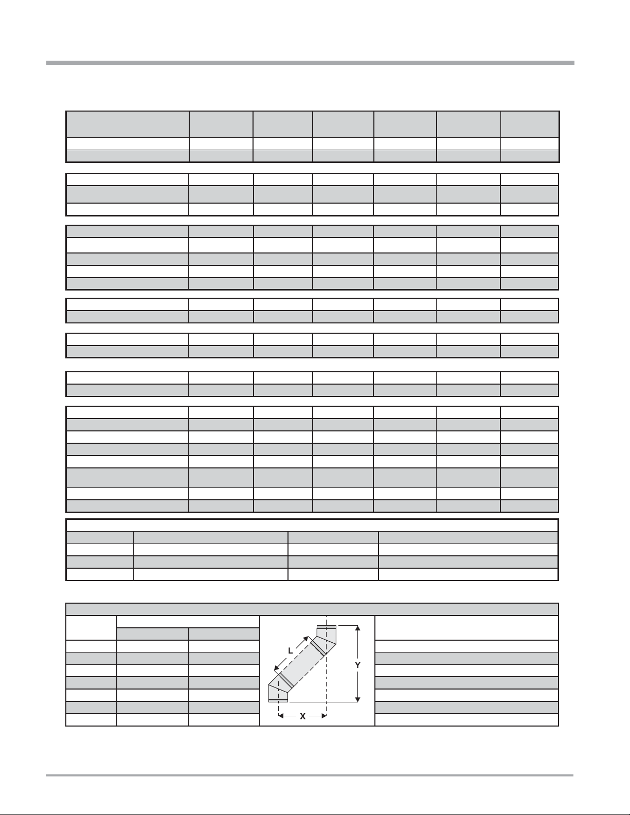
Description
Attic Insulation Shield 12” 46DVA-IS N/A@ FPI N/A 4DAIS12 N/A SV4RSA N/A
Attic Insulation Shield -
Basic Horizontal Termination Kit (A) Disc. 4DT-HKA 4DHTK2 4DHTKA SV-SHK N/A
Horizontal Termination Kit (B) 46DVA-KHA
Vertical Termination Kit Disc. 4DT-VKC 4DHTK 4DHTK SV-FK N/A
High Wind Vertical Cap 46DVA-VCH N/A N/A N/A N/A TM-4VT
High Wind Horizontal Cap 46DVA-HC N/A N/A N/A N/A TM-4DHT
Horizontal Square Termination Cap See
Vertical Termination Cap N/A 4DT-HVC 4DVC 4DVT SV4CGV-1 TM-4VT
Storm Collar 46DVA-08A 4DT-SC 4DSC 4DSC SV4FC TM-SC
Adjustable Flashing 0/12-6/12 N/A 4DT-ST14 4D12S 4DST14 SV4STC14 TF-4FA
Adjustable Flashing 6/12-12/12 N/A 4DT-ST36 4D36S 4DST36 SV4STC36 TF-4FB
Vinyl Siding Standoff 46DVA-VSS 4DT-VS N/A 4DVS SV4VS TM-VSS
Vinyl Siding Shield Plate N/A 4DT-VSP N/A N/A SV4VS N/A
Snorkel Termination 14” 46DVA-VCH N/A N/A N/A N/A TM-4ST14
Snorkel Termination 36” 46DVA-HC N/A N/A N/A N/A TM-4ST36
Restrictor Disk 46DVA-RD N/A N/A N/A N/A TM-4DS
Extended Vertical Termination Cap 46DVA-VCE N/A N/A N/A N/A N/A
Chimney Conversion Kit A (USA only) 46DVA-KCA N/A N/A N/A N/A TM-4CA6
Chimney Conversion Kit B (USA only) 46DVA-KCB N/A N/A N/A N/A TM-4CA7
Chimney Conversion Kit C (USA only) 46DVA-KCC N/A N/A N/A N/A TM-4CA8
Chimney Conversion Kit Masonry
(USA only)
Wall Firestop 46DVA-WFS N/A N/A N/A N/A TM-4TR
Colinear Flex Connectors 46DVA-ADF N/A N/A N/A N/A N/A
Cold Climates 36” N/A N/A 4DAIS12 N/A N/A TM-4AS
Simpson
Direct Vent Pro
(Changed Components)
46DVA-HC 4DT-HHC 4DHC 4DHT SV4CHC-1 TM-4HT
46DVA-KMC N/A N/A N/A N/A N/A
®
Selkirk
Direct Temp™
4DT-HKB 4DHTK1 4DHTKB SV-HK N/A
American Metal
Products®
Amerivent Direct
Metal-Fab™
Sure Seal
Security
Secure- Vent®
ICC Excel
Direct
FPI
946-506/P Vent Guard (Optional) for AstroCap 946-205 Vinyl Siding Shield for Riser Vent Terminal
510-994 Rigid Pipe Adaptor (Must use with all rigid piping) 946-208/P Vent Guard (Optional) for Riser Vent Terminal
640-530/P Riser Vent Terminal 946-523/P AstroCap Horizontal Cap
946-605 Starter Collar Increaser 4” x 6-5/8” to 5” x 8” 946-206 Vinyl Siding Standoff for AstroCap
Note: When using Metal-Fab Sure Seal Rigid Piping - please note that the Adaptor (4DDA) must be used in conjunction with FPI Rigid Pipe Adaptor (510-994).
Offset Pipe Selection: Use this table to determine offset pipe lengths.
Pipe Length
(L)
0” (0mm) 4-7/8” (124mm) 13-7/8” (340mm) Simpson Direct Vent Pro: www.duravent.com
6” (152mm) 8” (203mm) 16-1/2” (419mm) Selkirk Direct-Temp: www.selkirkcorp.com
9” (229mm) 10-1/8” (257mm) 18-5/8” (473mm) American Metal Products: www.americanmetalproducts.com
12” (305mm) 12-1/4” (311mm) 20-3/4” (527mm) Metal-Fab Sure Seal: www.mtlfab.com
24” (610mm) 20-5/8” (524mm) 29-1/8” (740mm) Security Secure Vent: www.securitychimneys.com
36” (914mm) 29” (737mm) 37-1/2” (953mm) Industrial Chimney Company: www.icc-rsf.com
48” (1219mm) 37-7/16” (951mm) 45-15/16” (1167mm)
Note: Horizontal runs of vent must be level, or have a 1/4” rise for every 1 foot of run towards the termination.
Never allow the vent to run downward - this could cause high temperatures and may present a possible fi re hazard.
22
4” x 6-5/8” Venting For specifi c instructions on venting components - visit the
Run (X) Rise (Y)
manufacturers website listed below.
P36E-4 Zero Clearance Direct Vent Gas Fireplace
 Loading...