

Raymarine RC400 GPS User Manual

RC400
GPS Chartplotter
Owner’s Handbook
Document Number: 81237-2
Date: August 2004

ii RC400 GPS Chartplotter

iii
About this Handbook
Introduction
This handbook describes the RC400 Portable GPS Chartplotter. The
RC400 utilizes Satellite Differential (SD) signals for enhanced
navigational accuracy.
The RC400 GPS Chartplotter can be used portably with the supplied NiMH batteries or fix-mounted while connected to ship’s power. The
equipment is comprised of:
• 4 in Color LCD display with Chart holder compartment for a Navion-
®
ics
Gold Chart electronic chart card
• Internal GPS antenna
• Battery tray for portable operation
The RC400 GPS Chartplotter can output GPS and Waypoint data to
operate with other equipment, such as an autopilot or repeater instrument
connected via the NMEA 0183 interface.
Note: This handbook contains important information about installing,
using and maintaining your new Raymarine product. To get the best from
the product, please read this handbook thoroughly.
Conventions Used
Throughout this handbook, dedicated buttons are referred to in bold
capitals (for example, ENTER). Functions, modes of operation and
options are shown in normal capitals (for example, LIGHT).
Operating procedures, which may consist of a single key-press, or a
sequence of numbered steps, are indicated by a ➤ symbol in the margin.
When textual data is displayed on screen, any unavailable data is shown
as dashes, one per character.
Where procedures refer to Select, this implies using the trackpad to
highlight a function and then pressing the ENTER key.
© Raymarine Limited 2004

iv RC400 GPS Chartplotter
Important Information
This handbook contains important information on the installation and
operation of your new equipment. In order to obtain the best results in
operation and performance, please read this handbook thoroughly.
Raymarine’s Product Support representatives, or your authorized dealer,
are available to answer any questions you may have.
Intended Use
The Raymarine RC400 is a chartplotter display unit with a built-in GPS
receiver and internal GPS antenna. It is intended for marine navigation
purposes on recreational boats.
Warranty
To register your RC400 ownership, please take a few minutes to fill out
the Warranty registration card at the back of this handbook. It is very
important that you complete the owner information and return the card to
the factory in order to receive full warranty benefits.
Technical Accuracy
To the best of our knowledge, the information in this handbook was
correct as it went to press. However, our policy of continuous product
improvement and updating may change specifications without prior
notice. As a result, unavoidable differences between the product and
handbook may occur from time to time. Raymarine cannot accept
liability for any inaccuracies or omissions it may contain.
For the latest product information visit our website:
www.raymarine.com
EMC Conformance
All Raymarine equipment and accessories are designed to the best
industry standards for use in the recreational marine environment.
The design and manufacture of Raymarine equipment and accessories
conform to the appropriate Electromagnetic Compatibility (EMC)
standards, but correct installation is required to ensure that performance
is not compromised.

v
GPS Reception
GPS systems must have a clear horizon-to-horizon view to track
satellites. Because i ts GPS antenna is internal, the RC400 should ne ver be
mounted below deck.
The RC400 must be used outdoors to ensure proper GPS signal
reception. The internal antenna may not be able to obtain a fix if the unit
is operated indoors.
The RC400 may require several minutes to obtain a GPS fix the first time
you power up.
Failure to properly mount the chartplotter can result in poor performance.
Safety Notices
CAUTION: Product Installation
This equipment must be installed and operated in accordance with
the instructions contained in this handbook. Failure to do so could
result in poor product performance, personal injury and/or damage
to your boat.
CAUTION: Navigation Aid
Although we have designed this product to be accurate and reliable,
many factors can affect its performance. As a result, it should only be
used as an aid to navigation and should never replace common sense
and navigational judgement. Always maintain a permanent watch
so you can respond to situations as they develop.
WARNING: High Voltage
This unit contains high voltages. Adjustments require specialized
service procedures and tools available only to qualified service
technicians – there are no user serviceable parts or adjustments. The
operator should not remove the cover or attempt to service the unit.
CAUTION: Battery Usage
• Do not short the terminals.
• Do not solder cells directly into battery tray.
• Do not use charger cord if power plug or cable is damaged.
• Do not charge cells with + and – terminals reversed.
• Do not recharge cells if physically deformed or leaking.
• Only operate using four Alkaline or four Ni-MH cells.
• Only use Alkaline or Ni-MH cells. Do not use any other type.

vi RC400 GPS Chartplotter
• Do not mix Alkaline and Ni-MH cells.
• Do not dispose of cells in fire.
• Do not dismantle cells.
• Replace all cells at the same time.
• Charge and discharge under the ambient temperature men-
tioned in cell’s specifications.
• Using batteries in extreme conditions may affect their service life.
For example: extreme temperature, deep cycle, extreme overcharge and over discharge.
• The Ni-MH batteries included with your RC400 are not covered
by the unit’s warranty.
WARNING: Alkaline Battery Use
When using Alkaline batteries, ensure the BATTERY TYPE switch
inside unit is set to ALKALINE so that the cells are not charged when
the Power/NMEA cable is connected.
Charging Alkaline cells can cause a rupture of the safety seal,
resulting in fluid contamination of the unit. This can lead to
corrosion that could damage or destroy the unit.
Ni-MH Battery Recycling
This product is powered by rechargeable Nickel Metal Hydride (Ni-MH)
batteries. Ni-MH batteries contain chemically active materials that are
hazardous to the environment. When Ni-MH batteries can no longer hold
a charge, they should be disposed of properly.
The Rechargeable Battery Recycling Corporation (RBRC) has been
established in the US to provide a rechargeable battery recycling
program. Spent Ni-MH batteries can be forwarded to a facility that uses a
thermal recovery process to reclaim the heavy metals. Collecting and
recycling Ni-MH batteries preserves valuable resources and prevents
heavy metals form entering the waste system, landfills and incinerators.
When the useful life of your Ni-MH cells has expired, please return them
to a recycling center. To find the location of the recycling center in the US
nearest you, phone the RBRC at 1-800-822-8837 or point your web
browser to:
www.rbrc.com
Outside the US, please contact the battery recycling agency for your area.

vii
Contents
About this Handbook ........................................................................................... iii
Introduction .................................................................................iii
Conventions Used ........................................................................iii
Important Information ....................................................................................... iv
Intended Use ................................................................................iv
Warranty ...................................................................................... iv
Technical Accuracy ..................................................................... iv
EMC Conformance ...................................................................... iv
GPS Reception .............................................................................. v
Safety Notices ............................................................................... v
Ni-MH Battery Recycling ........................................................... vi
Chapter 1: Overview ..........................................................................................1
1.1 RC400 GPS Chartplotter .............................................................. 1
Display Features and Functions .................................................... 1
Operating Controls and Display Layout ....................................... 1
Trackpad and Cursor ............................................................... 2
Dedicated Keys ....................................................................... 3
Status Bar ................................................................................ 3
Function Bar ........................................................................... 3
Pop-Up Menus ........................................................................ 4
Database Lists ......................................................................... 4
1.2 Satellite Differential System ......................................................... 4
How it Works ................................................................................ 5
Availability of WAAS and EGNOS Signals .................................6
Broadcast Continuation and Accuracy .........................................6
Chapter 2: Installation .......................................................................................7
2.1 Introduction .................................................................................. 7
EMC Installation Guidelines ........................................................ 7
2.2 Unpacking and Inspecting the Components ................................. 7
Items Missing? .............................................................................. 8
2.3 Planning the Installation ............................................................... 9
2.4 Installing the Batteries and Chart Card ....................................... 11
Installing the Batteries ................................................................ 12
Inserting a Gold Chart Card ........................................................ 13
Removing a Gold Chart Card ..................................................... 14
2.5 Bracket Mounting ....................................................................... 14
2.6 Running the Cable ...................................................................... 16
Introduction ................................................................................ 16
2.7 Charging the Ni-MH Batteries .................................................... 18
Battery Voltage Indicator ............................................................ 18

viii RC400 GPS Chartplotter
2.8 System Check and Initial Switch On .......................................... 19
Initial Switch On .........................................................................19
Checking Chartplotter Operation ............................................... 20
EMC Conformance ..................................................................... 20
GPS Reception ............................................................................ 20
Chapter 3: Getting Started .............................................................................21
3.1 Introduction ................................................................................21
Battery Voltage Indicator ............................................................21
Simulator .................................................................................... 21
3.2 Switching On/Off ........................................................................22
Changing the Lighting and Contrast ........................................... 22
3.3 Simulator Mode .......................................................................... 23
3.4 Controlling the Display ............................................................... 24
Selecting the Display Mode ........................................................ 24
Moving Around the Chart ........................................................... 26
Using FIND SHIP ....................................................................... 26
Changing the Chart Scale ............................................................ 27
3.5 Using Navionics Gold Chart Cards .............................................29
Loading the Chart Data ............................................................... 29
Displaying the Chart Data ........................................................... 30
Chapter 4: Setting Up .......................................................................................31
4.1 Introduction ................................................................................31
4.2 System Set Up Parameters .......................................................... 31
Bearing Mode ............................................................................. 33
Units ............................................................................................ 34
Variation ...................................................................................... 34
Variation Mode ........................................................................... 34
Date Format ................................................................................ 34
Time Offset ................................................................................. 34
Language ....................................................................................34
Simulator .................................................................................... 35
Simulated SOG ...........................................................................35
Simulated COG ........................................................................... 35
Screen Saver ............................................................................... 36
Light Saver .................................................................................. 36
4.3 Chart Set Up Parameters ............................................................. 37
Orientation .................................................................................. 39
Plotter Mode ............................................................................... 39
Show Waypoints ......................................................................... 40
Waypoint Symbol ....................................................................... 40
Autozoom ................................................................................... 40
Screen Amplifier ......................................................................... 40

ix
COG Vector ................................................................................ 40
Arrival Circle .............................................................................. 40
Anchor Alarm ............................................................................. 41
XTE Alarm ................................................................................. 41
Select Chart ................................................................................. 41
Chart Text ................................................................................... 41
Chart Boundaries ........................................................................ 42
Safety Contours .......................................................................... 42
Depth Contours ........................................................................... 42
Spot Soundings ........................................................................... 42
Light Sectors ............................................................................... 42
Presentation ................................................................................ 42
Position Calibration ....................................................................42
4.4 GPS Setup ................................................................................... 43
Chapter 5: Operation .......................................................................................47
5.1 Introduction ................................................................................ 47
5.2 Working with Waypoints ............................................................ 47
Placing a Waypoint .....................................................................48
Selecting a Waypoint .................................................................. 50
Waypoint Data Display ............................................................... 51
Editing Waypoint Details ............................................................ 52
Erasing Waypoints ...................................................................... 54
Moving Waypoints ..................................................................... 54
5.3 Working with Routes ..................................................................55
Creating a New Route ................................................................. 56
Saving the Current Route ............................................................ 58
Clearing the Current Route from the Screen ............................... 59
Retrieving a Route from the Database ........................................59
Displaying Route Leg and Waypoint Information ...................... 60
Erasing or (re)Naming a Route ................................................... 61
Route Info ...................................................................................61
Editing a Route ........................................................................... 63
5.4 Following Routes and Going to Target Points ............................65
Follow a Route ............................................................................ 66
Reverse a Route .......................................................................... 66
Target Point Arrival .................................................................... 67
Alter a Route ............................................................................... 67
Going to an Individual Target ..................................................... 69
Go to a Waypoint ........................................................................ 69
Go to Cursor ................................................................................ 70
Go to a Port ................................................................................. 71
Stop Follow or Stop GoTo .......................................................... 72

x RC400 GPS Chartplotter
5.5 Changing the Display Mode .......................................................72
CDI Display ................................................................................73
BDI Display ................................................................................74
Waypoint Data ............................................................................ 76
Navigation Data .......................................................................... 78
Time/Date Data ........................................................................... 79
5.6 Transferring Waypoints and Routes ............................................81
Displayed Waypoints .................................................................. 81
Managing Database Lists ...................................................... 81
5.7 Using Tracks ............................................................................... 83
Setting up a Track ........................................................................83
Clearing the Current Track ......................................................... 85
SmartRoute ................................................................................. 85
5.8 Object Information ..................................................................... 86
5.9 Using Archives ...........................................................................87
Archiving a Route ....................................................................... 87
Loading or Deleting an Archived Route .....................................89
Archiving a Track .......................................................................90
Loading or Deleting an Archived Track ..................................... 91
Archiving a Waypoint Set ...........................................................93
Loading or Deleting an Archived Waypoint Set .........................94
5.10 Displaying Chart Information ..................................................... 96
Port Services ...............................................................................96
Tide Information ......................................................................... 98
5.11 Man Overboard (MOB) ............................................................ 104
5.12 Alarms ....................................................................................... 105
Chapter 6: Maintenance & Troubleshooting ..............................................107
6.1 Maintenance .............................................................................107
Routine Checks .........................................................................107
Servicing and Safety .................................................................107
6.2 Resetting the System ................................................................. 108
6.3 Problem Solving .......................................................................109
Troubleshooting ........................................................................109
6.4 How to Contact Raymarine ....................................................... 110
On the Internet .......................................................................... 110
Customer Support ..................................................................... 110
In the US ................................................................................... 110
In Europe ................................................................................... 112
Worldwide Support ................................................................... 112
Appendix A: Specifications ............................................................................113
Appendix B: List of Abbreviations ...............................................................115
Index ...........................................................................................117

Chapter 1: Overview 1
Chapter 1: Overview
1.1 RC400 GPS Chartplotter
Display Features and Functions
The RC400 GPS Chartplotter includes the following features:
• Detailed navigation information from installed Navionics
Chart card
• Positional information from Satellite Differential GPS
• GPS satellite status
• Create, Place, Move, Edit or Erase a Waypoint
• GoTo Waypoint, Port, Facility or Cursor
• Create, Save, Name, Edit or Follow a Route
• Review Route and Waypoint Lists
• Display Tide Heights, Tide Currents, Sun and Moon data
• Display vessel’s position, direction and track on-screen
• Convert a track to a route (SmartRoute)
• Alarms and Timers
• Man OverBoard (MOB) to navigate back to a missing person or
object
• Display and keys illuminated for night-time use
®
Gold
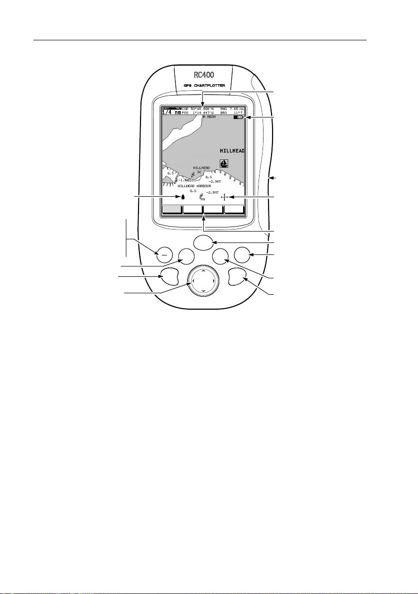
Operating Controls and Display Layout
The chartplotter is operated by means of the following controls:
• A multi-direction trackpad with context sensitive cursor
• Seven dedicated and labelled push-buttons
The main navigation display also features:
• Dedicated status panel
• Dynamic function bar
• On-screen pop-up menus
• Database lists for storing waypoints and routes
2 RC400 GPS Chartplotter
Status bar
Battery strength
Chart card compartment
(under battery tray, rear)
Vessel Symbol
GOTO is for following a route or for
going to a waypoint, port, nearest
facility or current cursor position.
MOB is for returning to a location if
a person or object is lost overboard.
ENTER accepts soft key selections.
RANGE IN zooms in to display a
smaller chart area.
TRACKPAD navigates through soft
key selections maneuvers the cursor.
FIND SHIP ROUTES
GOTO
ENTER
MOB
RANGE
IN
WAYPOINTS
POWER
CLEAR
MORE¬
RANGE
D6530-2
PAGE
OUT
Cursor
Primary Function Bar
POWER toggles the unit on and off.
PAGE toggles between Set Up, CDI,
BDI, Waypoints, Navigation and
Time/Date display modes.
CLEAR exits a function or backs up
one menu level.
RANGE OUT zooms out to display
a larger chart area.
Figure 1-1: RC400 GPS Chartplotter Operating Controls
Trackpad and Cursor
On the primary chart display, the trackpad is used to move the cursor
horizontally, vertically or diagonally. The cursor is the cross-hair symbol
(+) which is used to select a position or item on the chart.
The longer the trackpad is pressed, the faster the cursor moves. The
current cursor position (in latitude and longitude) is shown in the status
bar at the top of the screen.
The cursor is context-sensitive. Some items on the screen, such as
waypoints and chart objects have information associated with them.
When the cursor is placed over such objects, this information is displayed
in the status bar. Some items may also have options or settings. If
available, these are displayed in a function bar at the bottom of the screen.
Note: During many operations the cursor cannot be moved around the
screen (while a function bar is displayed, for example) and the cursor is
used exclusively for selection.

Chapter 1: Overview 3
Dedicated Keys
These keys have fixed functions. Some keys can be used in either of two
ways:
• Press: Press the key briefly and then release it. This method is used
for most key operations.
• Press and hold: Press the key, keep it pressed for the period of time
stated (typically 3 seconds), then release it.
When a dedicated key is pressed, one of the following occurs:
1. The associated operation occurs (for example, change chart scale—
RANGE IN/OUT key).
2. A pop-up menu is displayed, providing further options.
3. A set of functions is displayed.
Status Bar
On the primary chart display, the status bar at the top of the screen
provides context-sensitive information. In general operation this will be
the scale of the chart, the position of the cursor (lat. and long) and the
range and bearing to the cursor. When the cursor is placed over a dynamic
object, the status bar will display information appropriate to that object.
Function Bar
The Function Bar at the bottom of the screen contains a number of
functions which change according to the current operation. The functions
are grouped into related sets and subsets providing access to the various
functions. The primary function bar is displayed when the ENTER key is
pressed.
The currently selected function is highlighted with a green background.
When a function is invoked, one of the following occurs:
1. The associated operation is performed (for example: GOTO WAY-
POINT).
2. A sub-set of functions is displayed.
3. A pop-up menu is displayed, providing further options.
4. The appropriate database list (for example, Route or Waypoint) is displayed.

4 RC400 GPS Chartplotter
Pop-Up Menus
Pop-up menus usually provide various options. When a pop-up menu is
on-screen, a set of associated functions is also displayed.
Use the trackpad to select an option from the menu, then use the
appropriate function to set the option. For example, the radius of the
waypoint arrival alarm can be specified or the selected navigation data
can be set on/off.
Database Lists
Waypoints and routes created on the chartplotter are stored in database
lists. These lists can be viewed and items selected for editing.
As with pop-up menus, when a database list is on-screen, a set of
associated soft keys is also displayed; use the trackpad to select an item
from the list, then use the appropriate function to edit the item. For
example, a Waypoint or a Route can be erased.
1.2 Satellite Differential System
The RC400 GPS Antenna utilizes a satellite differential correction
system to improve the accuracy and integrity of the basic GPS signals.
Three separate compatible systems currently exist or are in development:
1. Wide Area Augmentation System (WAAS). Developed by the Federal Aviation Administration (FAA) in the USA.
2. European Geostationary Navigation Overlay System (EGNOS).
This system is being developed by a European consortium.
3. The MTSAT Satellite-Based Augmentation System (MSAS). Being
developed by the Japan Civil Aviation Bureau (JCAB) for civil aviation use.
The area covered by the WAAS system includes the entire United States
of America but also extends to a much wider area as detailed below.

Chapter 1: Overview 5
0˚15˚W30˚W45˚W60˚W90˚W 75˚W105˚W120˚W135˚W150˚W165˚W 15˚E135˚E 150˚E 165˚E 180˚
75˚N
60˚N
45˚N
30˚N
15˚N
0˚
15˚S
D4910-1
Figure 1-2: WAAS Coverage Map
The combination of the WAAS, EGNOS and MSAS systems will
provide global satellite based differential GPS augmentation into the
future.
How it Works
The following description is based on WAAS, but the principles apply
equally to the EGNOS and MSAS systems.
WAAS comprises the following components:
• Ground Reference Stations across the USA
• Master Stations located at East Coast and West Coast
• Geostationary Satellites located above the equator
The Ground Reference Stations are located at known positions and
receive data continuously from GPS. The Ground Reference Stations
send their data to the Master Stations which calculate the error of the
GPS-received positions and generate correctional data.
The corrected “differential” signals are then sent to the two
Geostationary Satellites which broadcast the corrected data on the
standard GPS frequency, making it available to the GPS Antenna.
The RC400 GPS uses the correctional data transmitted by the
Geostationary Satellites to refine the basic GPS positional data for
greater accuracy.

6 RC400 GPS Chartplotter
Figure 1-3: The WAAS System
Availability of WAAS and EGNOS Signals
The WAAS system is presently broadcasting in North America.
The RC400 GPS Chartplotter is EGNOS compatible. However, at the
time of going to print the EGNOS was still under test.
Further information on the WAAS and EGNOS systems can be found at:
www.raymarine.com
Broadcast Continuation and Accuracy
The continuation of the broadcast SD signals is not the responsibility of
Raymarine. The navigational accuracy of equipment using these satellite
broadcast SD signals is not guaranteed.

Chapter 2: Installation 7
Chapter 2: Installation
2.1 Introduction
This chapter provides instructions to assist in planning the installation of
the RC400 GPS Chartplotter.
EMC Installation Guidelines
All Raymarine equipment and accessories are designed to the best
industry standards for use in the recreational marine environment.
Their design and manufacture conforms to the appropriate
Electromagnetic Com patibility (EMC) standards, but cor rect installation
is required to ensure that performance is not compromised. Although
every effort has been taken to ensure that they will perform under all
conditions, it is important to understand what factors could affect the
operation of the product.
For optimum EMC performance, it is recommended that when using the
ship’s power:
• Raymarine equipment and cables connected to it are:
• At least 3 ft (1 m) from any equipment transmitting or cables carry-
ing radio signals (for example: VHF radios, cables and antennas.)
• More than 7 ft (2 m) from the path of a radar beam. A radar beam
can normally be assumed to spread 20 degrees above and below
the radiating element.
• Raymarine specified cables are used. Cutting and rejoining these
cables can compromise EMC performance and must be avoided
unless doing so is detailed in the installation manual.
• If a suppression ferrite is attached to a cable, this ferrite should not be
removed. If the ferrite needs to be removed during installation it must
be reassembled in the same position.
2.2 Unpacking and Inspecting the Components
Unpack your RC400 GPS Chartplotter carefully. Retain the carton and
packing materials in the event that you need to return the unit for service.
Check that you have all the correct system components.

8 RC400 GPS Chartplotter
Part Number Description
E33018 RC400 GPS Chartplotter
R38095 Mounting Bracket Base
R38096 Mounting Bracket Adapter
R38097 Mounting Knob
— AA size Ni-MH batteries x 4
R38098 Carrying Case
R38099 Power/NMEA cable
R38100 12VDC Cigarette Lighter Adapter
R38102 RC400 Battery Tray
81237 RC400 Handbook
Items Missing?
If any of the above items is missing or damaged, please contact your
Raymarine dealer or our Product Support Department to obtain
replacements.

Chapter 2: Installation 9
2.3 Planning the Installation
When planning to install your RC400 using the bracket mount and ship’s
power, the following points should be considered to ensure reliable and
trouble free operation:
• Convenience: The unit should be installed in a convenient position
where it can be viewed straight on or with a viewing angle of less than
35°. You may wish to apply power before you install the unit, to determine the best viewing angle prior to fixing. The mounting location
should be easily accessible to allow operation of the controls.
• Access: There must be sufficient space below the unit to allow cable
connection to the bottom connector, avoiding tight bends in the cable.
• Interference: The selected location should be far enough away from
devices that may cause interference, such as motors and generators.
• Power Source: The unit should be located near a DC power source.
The power cable supplied is 1.5m (5ft), but a longer cable can be used
if required. Power must be supplied via a 1A quick blow fuse or circuit breaker. Refer to Running the Cable on page 16.
• Interconnections: The unit transmits navigation and waypoint data
on NMEA and, therefore, can be connected to an NMEA compatible
devices. The navigation data transmitted by the chartplotter is
detailed in Appendix A.
• Environment: The unit should be protected from physical damage,
heat sources and excessive vibration. Although the unit is waterproof,
it is good practice to mount it in a protected area aw ay from prolonged
and direct exposure to rain and/or salt spray.
The dimensions of the unit are shown in Figure 2-1 .

10 RC400 GPS Chartplotter
3.57" (90.57mm)
1.75"
(44.52mm)
6.48"
(164.6mm)
GOTO
MOB
RANGE
POWER
PAGE
ENTER
IN
CLEAR
RANGE
OUT
Figure 2-1: RC400 Dimensions
D6523-2
Chapter 2: Installation 11
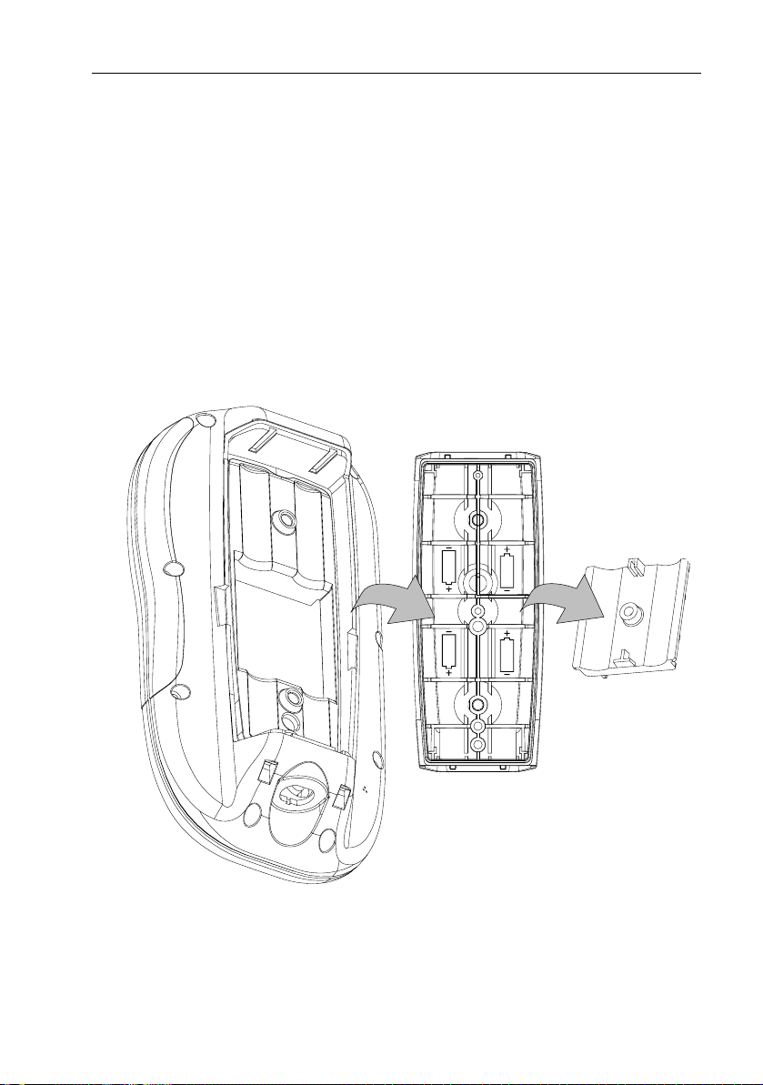
2.4 Installing the Batteries and Chart Card
Before using the RC400, you must install the Navionics Gold Chart Card
and, if being used portably, the batteries. The chart card is inserted in the
rear of the RC400, beneath the battery tray.
Installing the AA cells and the chart card both require first removing the
battery tray.
➤ To remove the battery tray:
1. Loosen the two retaining screws on the rear of the unit.
2. Remove the battery tray.
3. Loosen the single retaining screw on the battery cover.
4. Remove the battery cover.
D6527-1
Figure 2-2: Removing the Battery Tray
Battery Cover
Battery Tray

12 RC400 GPS Chartplotter
Installing the Batteries
When used portably, the RC400 can be powered by the supplied four (4)
Nickel Metal Hydride (Ni-MH) batteries or with four (4) AA alkaline cells
(not supplied), using the supplied Battery Tray.
Note: The RC400 was designed to be used with all Ni-MH or all alkaline
battery cells only. Do not mix or use any other battery types.
➤ To install batteries:
1. Remove the battery tray as shown in Figure 2-2 .
2. Locate the Battery Type switch on the inside of the chartplotter adjacent to the chart card (if already installed) and turn to the appropriate
position: ALKALINE or RECHARGEABLE.
D6521-1
BATTERY TYPE switch
Figure 2-3: Locating the BATTERY TYPE Switch
3. Noting the proper orientation, install the 4 cells into the Battery Tray.
4. Noting the proper orientation shown in Figure 2-2 , replace the Bat-
tery Cover and tighten the retaining screw.
5. Push the battery tray into the RC400. The tray will only install one
way: The raised fin on one edge of the Battery Cover must be inserted
over the BATTERY TYPE label so that there will be sufficient room
for the chart card.
6. Turn the screw at the base of the battery case clockwise to the LOCK
position.

Chapter 2: Installation 13
WARNING:
When using Alkaline cells, set the battery type switch to ALKALINE
so that the cells are not charged when the NMEA cord is connected.
Charging Alkaline cells may cause excessive heat and could result in
cell leakage or explosion causing damage or injury.
Inserting a Gold Chart Card
Charts with detailed information for the area you wish to navigate are
available on Navionics Gold Chart cards, each of which can store up to 20
charts in an electronic format. See Using Navionics Gold Chart Cards on
page 29 for details.
➤ To insert a Gold Chart card, refer to Figure 2-4 :
1. Check that you are using the correct Gold Chart card for the desired
area.
2. Remove the battery tray as described above and in Figure 2-2 .
3. Insert the card as shown in Figure 2-4 with the smooth edge of the
card outermost and the card label up.
4. Gently press the card home. If inserted correctly the words BATTERY TYPE on the label behind the card will be visible.
5. Replace the battery tray and tighten the retaining screws.
Figure 2-4: Inserting the Gold Chart Card
D6522-1

14 RC400 GPS Chartplotter
Removing a Gold Chart Card
CAUTION:
Do not use a metallic instrument (such as a screwdriver or pliers) to
aid removal, as this can cause irreparable damage.
➤ To remove a Gold Chart card:
1. Loosen the two retaining screws on the rear of the unit.
2. Remove the battery tray as described above in Figure 2-2 .
3. Grip the card lip with a fingernail and pull to the side to remove it
from its slot.
4. Flip unit over so card drops out.
2.5 Bracket Mounting
The unit can be conveniently bracket-mounted on a dash area or
deckhead. Mount the unit as shown in Figure 2-5 :
1. Using the mounting base as a template (or using the template at the
end of this handbook), mark the locations of the screw holes on the
mounting surface.
2. Drill the holes where marked.
3. Use the supplied hardware to fix the mounting base at the marked
locations.
4. Attach the mounting bracket to the mounting base as shown.
5. Attach the knob. Adjust the display angle and tighten the knob.
6. Slide the RC400 downward onto the mounting bracket until the tabs
at the bottom of the bracket enter the corresponding indentations on
the chartplotter.
7. Firmly press the RC400 onto the bracket until it clicks into place.

Chapter 2: Installation 15
➤ To remove the RC400 from the mounting bracket assembly:
1. Use the thumb on one hand to depress one of the two release tabs on
either side of the mounting bracket.
2. Grasping the RC400 with the other hand, pull the chartplotter forward
and remove from the bracket.
Release Tabs
Mounting Knob
Mounting Bracket
D6528-1
Bracket Base
Figure 2-5: RC400 Bracket Mounting Arrangement

16 RC400 GPS Chartplotter
2.6 Running the Cable
Introduction
A cable is required to supply power for operating the unit, charging its
batteries and providing NMEA connection on board your vessel. Of
course you can also charge the unit with the Cigarette Lighter Adapter.
Notes: (1) Adequately secure the Power/NMEA cable and protect from
physical damage. Avoid running cable through bilges, doorways
or close to moving objects or heat sources.
(2) Where a cable passes through an exposed bulkhead or deckhead, a swan neck tube should be used.
(3) Where the cable will be exposed to the elements, a suitable
drip loop should be used.
POWER/NMEA Connector
CAUTION:
If you do not have a breaker in your power circuit, you must fit an inline 1A quick-blow fuse to the positive (red) lead of the power cable.
This unit is not intended for use on positive ground vessels.
The POWER/NMEA connector provides for 12VDC power connection
and NMEA inputs/outputs using the supplied cable.
The chartplotter is intended for use on vessel’s DC power systems
operating in the range 10.0VDC to 18.0VDC (in other words, 12V
systems, not 24V or 32V systems).
Power connections should be made at a DC power distribution panel
through an isolator switch and a 1A circuit breaker or 1A quick blow fuse.
All connections must be clean and tight.
The DC power system should be either:
• Negative ground, with the negative battery terminal connected to the
vessel’s ground
• Floating, with neither battery terminal connected to the vessel’s
ground
A 1.5m (5ft) power cable is supplied. If a longer power cable run is
required, use the supplied power cable to connect to the unit plus a
suitable connector block to connect to the extension cable. The supplied
power cable cores have a cross-section of 2.0mm
Longer power cable runs may require larger wire gauges to minimize any
voltage drop in the cable.
2
(15 AWG).

Chapter 2: Installation 17
If the power cable must be extended, estimate the length of cable between
the vessel’s main power source and the connector block, then select the
correct wire size determined by the distance as indicated below.
Wire size AWG: 16 15 14 12 10 8
Wire size in mm
Maximum Extension (feet): 36 49 65 98 147 230
Maximum Extension (meters): 11.0 15.0 20.0 3 0.0 45.0 70.0
2
:
1.5 2.0 2.5 4.0 6.0 10.0
The DC power input should be connected to the POWER cable at the
bottom of the chartplotter. The cable colors are detailed below.
Pin Function Color
1DC Power In + Red
2DC Power In – Black
3NMEA In+ Brown
4NMEA In– Yellow
5NMEA Out+ Violet
6NMEA Out– White
Shield Drain/Screen (bare wire)
➤ Connect to the power supply using the power cable supplied:
1. Connect the molded connector (with the arrow facing you) to the connector on the bottom of the chartplotter. Run the free end back to the
vessel’s distribution panel or to a junction box.
Note: The molded power connector is spring-loaded to ensure a positive
lock. When removing, press down on the outer ring as you pull the connector away from the RC400. This will prevent damage to the connector.
2. Cut the cable to length and connect the red wire (via a 1A quick blow
fuse) to the + battery terminal and the black wire to the – terminal.
3. Use a suitable junction box to connect to any NMEA equipment.
4. Cut any unused wires short or insulate and tape back.
CAUTION: If the power connections are accidentally reversed, the
system will not function. Use a voltmeter to check that the input
power leads are connected with the correct polarity.

18 RC400 GPS Chartplotter
Cigarette Lighter Adapter
You can also power the RC400 and charge batteries using the supplied
12VDC Cigarette Lighter Adapter. This adapter contains a 1.5A fuse,
which is located inside the plug that is inserted into the cigarette lighter.
To open, unscrew the tip until it separates from the rest of the plug.
Replace fuse with one of the same rating.
Figure 2-6: Opening the Cigarette Lighter Adapter
2.7 Charging the Ni-MH Batteries
After connecting the RC400 to power you are ready to charge the batteries.
Although some voltage may be measured on the Ni-MH batteries initially,
they must be fully charged before normal use.
1. Insert the batteries into the battery pack as described in Section 2.4,
Installing the Batteries and Chart Card.
2. Connect the Power/NMEA cable to ship’s power.
—or—
Connect the Cigarette Lighter Adapter into a 12 VDC cigarette lighter.
3. Connect the molded plug, with the arrow facing you, into the connector
on the bottom of the RC400.
4. Fully charge for 6 hours.
Battery Voltage Indicator
NEEDS CHARGING
FULLY CHARGED
When battery charging is complete, the message BATTERY CHARGE
COMPLETED appears on the screen. When the unit is in need of charging,
the message BATTERY LOW appears on the screen.
When the RC400 is being used in portable mode, an icon
displays the status of the AA batteries. The icon located in
the upper right corner of the screen, below the status bar.
When the batteries are completely discharged, the battery
icon appears empty. When fully charged, the battery icon
appears full. The figure to the left indicates the six status
levels the battery level icon can display.
Chapter 2: Installation 19
2.8 System Check and Initial Switch On
When installation is complete and all connections have been made, recheck the installation before using the system for navigation. If problems
occur, refer to Chapter 6:Maintenance & Troubleshooting.
Initial Switch On
To switch on the chartplotter, press the POWER key.
If necessary, adjust the lighting and contrast (see Chapter 4).
If desired, change the default language settings as follows:
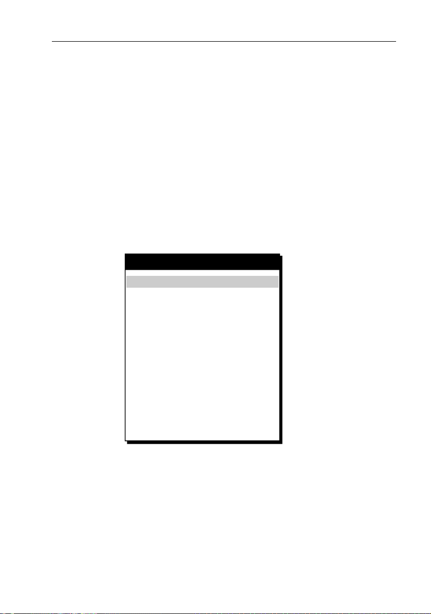
1. Press the PAGE key to display the setup function bar.
2. Using trackpad left/right, select the SYSTEM SET UP function and press
ENTER. The SYSTEM SET UP menu is displayed, listing the parameters
and their current settings:
SYSTEM SET UP
BEARING MODE
DISTANCE UNITS
SPEED UNITS KNOTS
DEPTH UNITS
VARIATION
VARIATION MODE AUTO
DATE FORMAT
TIME OFFSET
LANGUAGE
SIMULATOR
SIMULATED SOG
SIMULATED COG ____
SCREEN SAVER
LIGHT SAVER
TRUE
NM
METRES
_.__
DD/MM/YY
UTC
ENGLISH
OFF
____
OFF
OFF
D6531-1
Figure 2-7: System Set Up Menu
3. Using trackpad up/down, select the LANGUAGE option.
4. Using trackpad left/right, select the desired language.
5. Press ENTER to return to the setup functions. The chartplotter now
uses the selected language.
6. Press CLEAR to return to the normal chart screen.

20 RC400 GPS Chartplotter
Checking Chartplotter Operation
To confirm that the chartplotter is operating correctly, perform the
following checks:
1. Press the trackpad left/right, up/down and check cursor movement
and normal scrolling action.
2. Insert a Navionics Gold Chart
You are asked to select one to use (See Select Chart on page 41)
3. Use the RANGE IN key to zoom-in and check that the new chart cartridge data is displayed.
4. Ensure that position data is available; use the FIND SHIP function to
check that the cursor is fixed on the vessel symbol which is correctly
positioned at the center of the chart display, see Chapter 5:Operation.
®
card for the area of your vessel.
EMC Conformance
Always check the installation before going to sea to make sure that it is
not affected by radio transmissions, engine starting, etc.
GPS Reception
The RC400 must be used outdoors to ensure proper GPS signal
reception. The internal antenna may not be able to obtain a fix if the unit
is operated indoors or below decks.
The RC400 may require several minutes to obtain a GPS fix the first time
you power up.
 Loading...